Getting Started with the MyoWare® 2.0 Muscle Sensor Ecosystem
 QCPete,
  bboyho
Arduino Example 3: Transmitting Sensor Data via Bluetooth® using the Wireless Shield (ESP32)
The following example requires the Wireless Shield and a BLE module to send and receive sensor data from one muscle sensor. This is useful for users that need a clean signal or want to transmit the sensor data wirelessly.
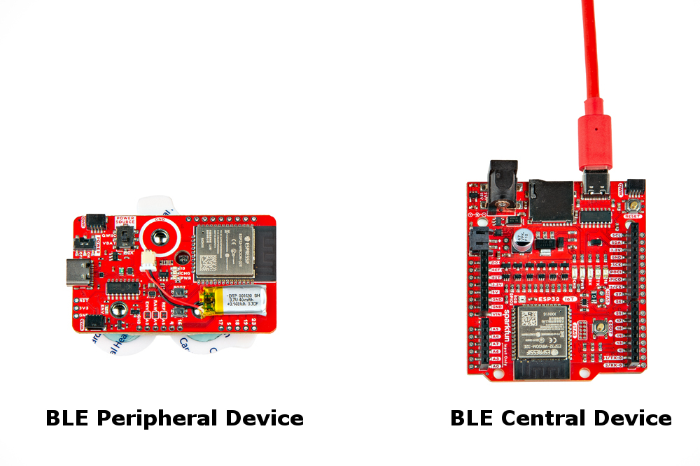
For an explanation of how Bluetooth peripheral and central devices work, we recommend looking at the Arduino reference language under the ArduinoBLE Library for a quick introduction.
- Arduino IDE v2.3.2
- esp32 by Espressif Systems v2.0.14
- ArduinoBLE by Arduino v1.3.6
- MyoWare Arduino Library v1.0.0
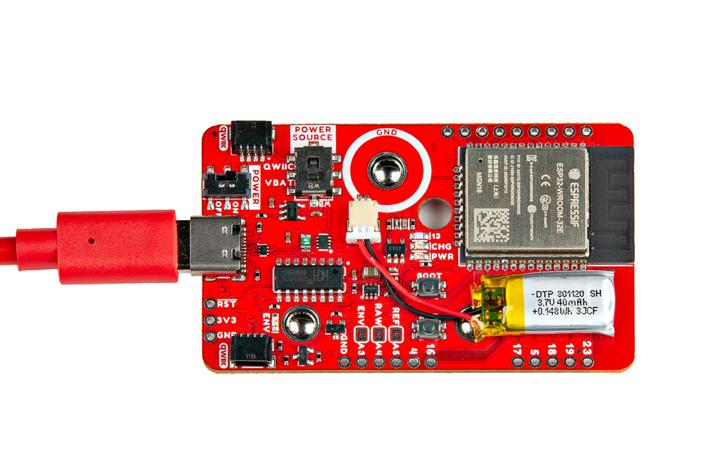
Example 3a: Bluetooth Peripheral "Send"
This example is for those that are modifying the firmware on the MyoWare 2.0 Wireless Shield. This is useful if you have more than one peripheral device. The example code uses a MyoWare 2.0 Wireless Shield to transmit the analog reading wirelessly via Bluetooth. Connect the MyoWare 2.0 Wireless Shield to your Computer if you have not already. Select the Power Source and flip the power switch to the ON position.
This particular example uses code from the MyoWare Arduino Library which is located in a different GitHub repository. With the library installed, head to the menu and select the following: File > Examples > MyoWare Arduino Library > MyoWareBLEPeripheral.
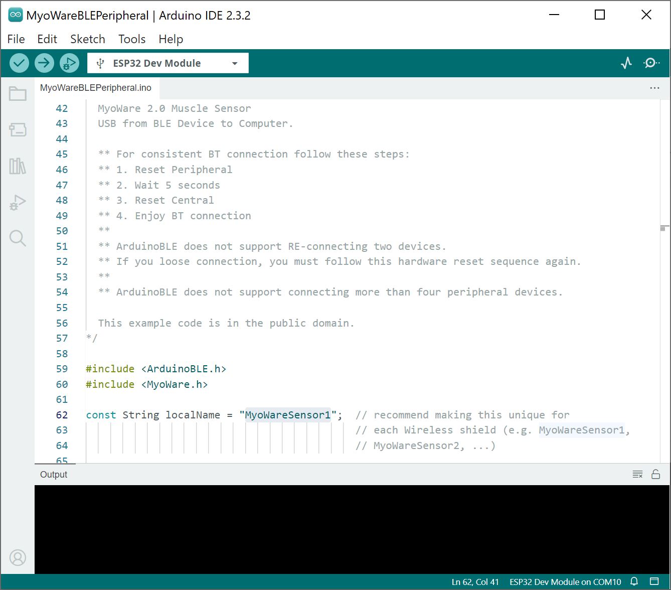
By default, the Wireless Shield includes firmware to act as a peripheral device. For users connecting more than one Wireless Shield to your central device, we recommend changing the BLE peripheral device name with a unique name. For this example, you would change the number in the following line of code in the MyoWareBLEPeripheral.ino for each additional peripheral device:
language:c
const String localName = "MyoWareSensor1";  // recommend making this unique for
                                            // each Wireless shield (e.g. MyoWareSensor1,
                                            // MyoWareSensor2, ...)</code></pre>
The second Wireless Shield would need to have the localname changed to MyoWareSensor2.
language:c
const String localName = "MyoWareSensor2";  // recommend making this unique for
                                                // each Wireless shield (e.g. MyoWareSensor1,
                                                // MyoWareSensor2, ...)
If you have not already, select your Board and associated COM port (in this case, the ESP32 Dev Module on COM10). Then upload the modified code to the board.
Example 3b: Bluetooth Central "Receive"
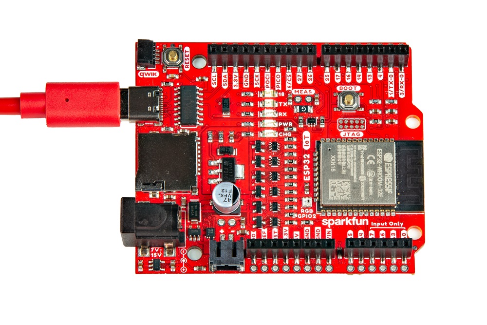
The following example uses an IoT RedBoard - ESP32 to receive the analog reading from the peripheral MyoWare 2.0 Wireless Shield. Of course, users can also use other Arduino boards that support Arduino BLE. Connect the IoT RedBoard - ESP32 to your computer if you have not already.
This particular example uses code from the MyoWare Arduino Library as well. With the library installed, head to the menu and select the following: File > Examples > MyoWare Arduino Library > MyoWareBLECentral .
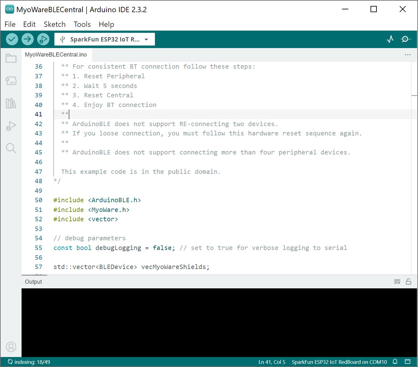
If you have not already, select your Board and associated COM port (in this case, the SparkFun ESP32 IoT RedBoard on COM10). Then upload the code to the board.
What You Should See
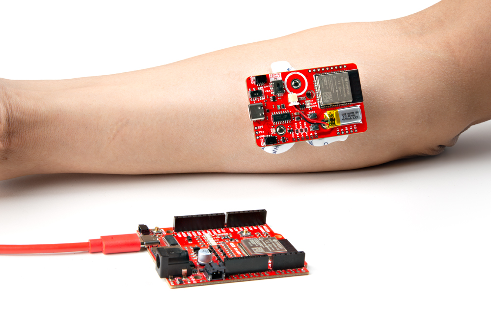
Choose a target muscle group, prepare the skin with alcohol wipes, remove the backs of the electrodes, and attach the stack to a muscle group. In this case, we used the forearm. Turn the POWER switch to the ON position.
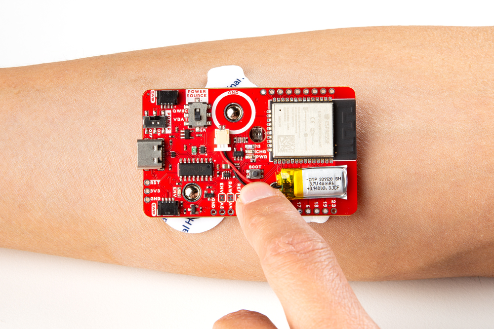
With the IoT RedBoard - ESP32 still connected to your computer, open Arduino Serial Monitor set at 115200 baud. If the Bluetooth fails to connect, try pushing the reset button on the Peripheral first, wait about 5 seconds, then hit the reset button on the Central.
- Reset Peripheral
- Wait 5 seconds
- Reset Central
- Enjoy BT Connection
 |
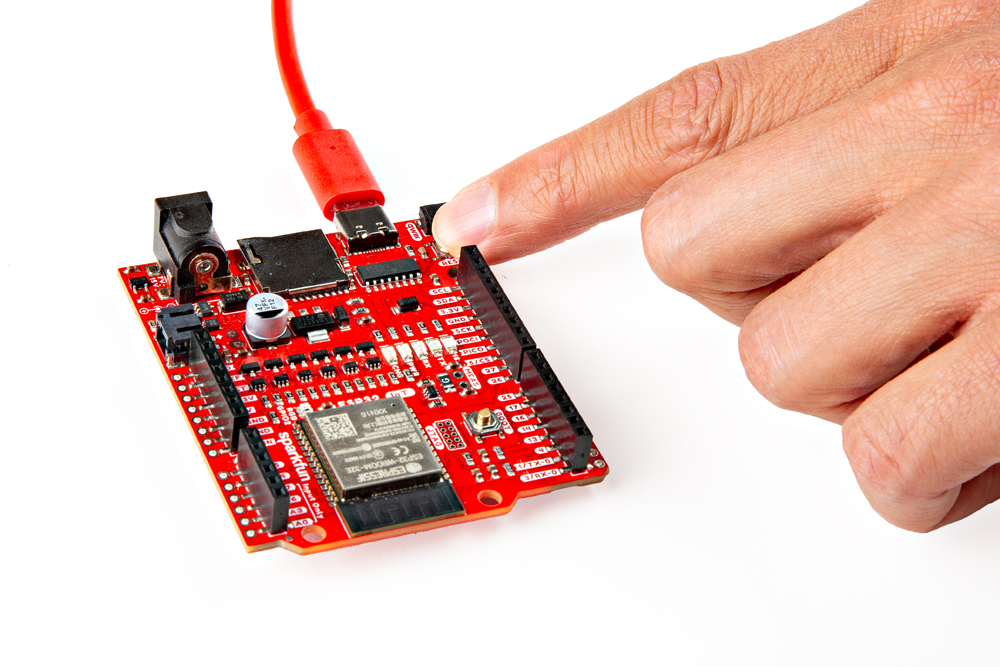 |
| Reset MyoWare 2.0 Wireless Sensor | Reset IoT RedBoard - ESP32 |
Once connected, the muscle sensor readings will be transmitted wirelessly to the central device. Try flexing your muscle to see if you can see the values increase. Below are the readings in the Serial Monitor and Serial Plotter while flexing and then relaxing a forearm muscle.
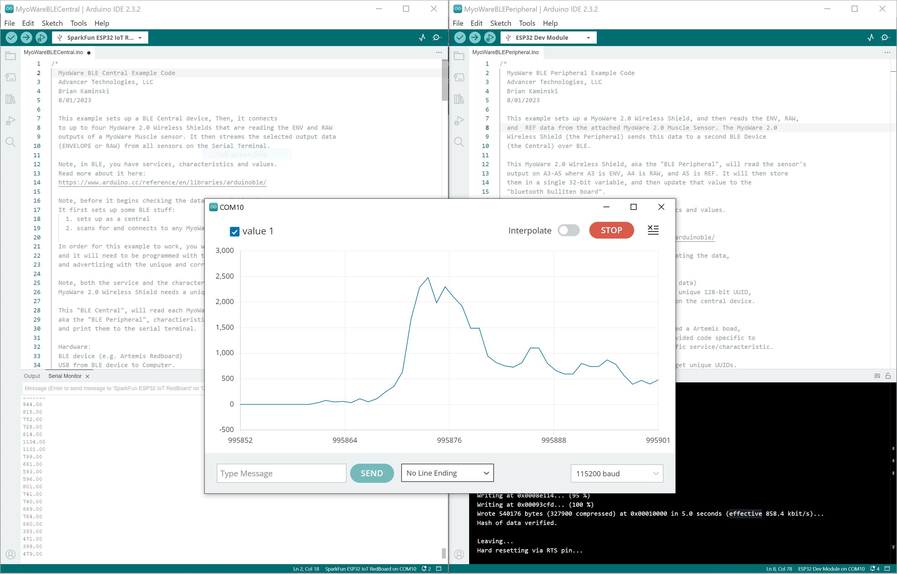
For users looking for a graphical view of the output, close the Arduino Serial Monitor for the Bluetooth set as the Central device (i.e the IoT RedBoard - ESP32 receiving the sensor data). Then open the Arduino Serial Plotter. You should see something similar to the output as shown above. In this case, we flexed our forearm muscle causing the values to increase. Relaxing the muscle caused the values to decrease.