Getting Started with the MyoWare® 2.0 Muscle Sensor Ecosystem
 QCPete,
  bboyho
MyoWare 2.0 LED Shield
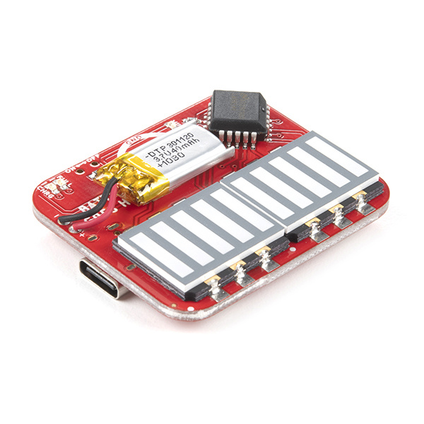
The MyoWare 2.0 LED Shield is designed to display the magnitude of a target muscle's signal and power the MyoWare 2.0 Muscle Sensor with its built-in battery. The blue 10-segment bar graph shows the magnitude of the measured signal. The more muscle activation measured, the higher up the board LEDs will go! With this shield, you will be provided with a visual representation of the signals provided by the MyoWare 2.0 Muscle Sensor. The LED shield is equipped with snap connectors on the board so you can easily stack it on the top side of the MyoWare 2.0 Muscle Sensor and flip the switch to the ON position to give the sensor all the power it needs to work its myoelectric magic. Connecting the MyoWare 2.0 Muscle Sensor to the battery power allows for a cleaner signal while also eliminating the possibility of creating a dangerous current path to the power grid. Use it to gauge how hard you’re working a muscle during a workout, as a teaching tool, or add some myoelectric flair to your Halloween costume!
MyoWare 2.0 LED Shield
DEV-18387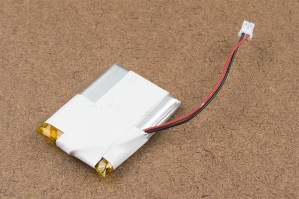
Hardware Overview
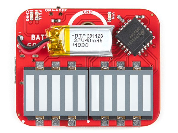
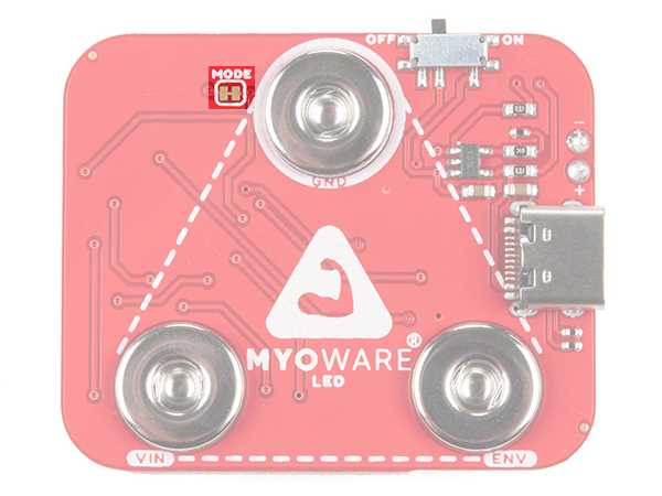
The top side of the board has the LEDs and LiPo battery. The bottom side has the female snap pins, power switch, and USB connector.
 |
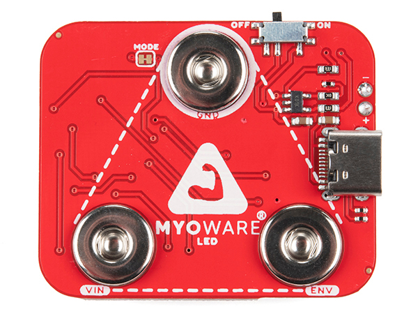 |
| Top Side | Bottom Side |
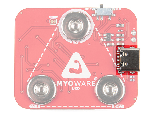
USB C Connector
Included on the board is a USB Type C connector. Plug in a USB C cable to a 5V power source to charge the single cell LiPo battery.
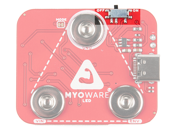
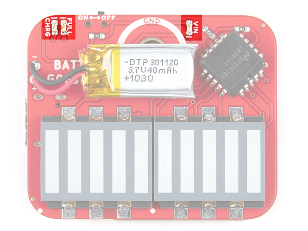
Power Switch
The board includes a power switch. Flip the switch to the ON position to provide power to the MyoWare 2.0 Muscle Sensor via the VIN's female snap connector. When not in use, flip the switch to the OFF position.
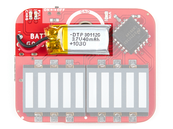
LiPo Charger
The board includes the MCP73831 LiPo charger IC to safely charge a single cell LiPo battery. In this case, the charge rate is set to 40mA to charge the 40mAh LiPo battery on the board. The charge status of your battery is indicated by the charge (CHRG) and full (FULL) LEDs.
 |
 |
| Top Side | Bottom Side |
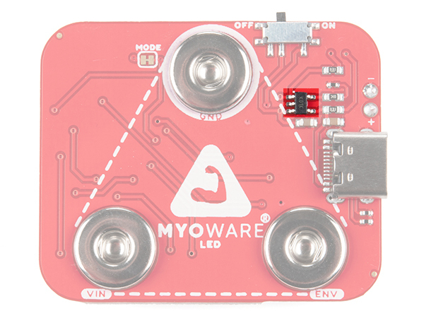
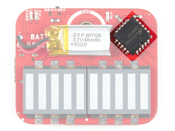
LM3914 Dot/Bar Driver
The black square IC is the LM3914 Dot/Bar Driver. This IC takes the output from the muscle sensor and outputs it to the 2x5 segment LEDs.
LEDs
The board includes three status LEDs.
- FULL - The FULL LED lights up to indicate when the battery is fully charged. This will be off when the LiPo is not charging or when the charger is not connected to the board.
- CHRG - The CHRG LED lights up to indicate when the LiPo battery is charging. This will be off when the LiPo is fully charged or when the charger is not connected to the board.
- VIN - The VIN LED lights up when the power switch is flipped to the ON position to indicate when the board is providing power for the MyoWare 2.0 Muscle Sensor through the VIN snap pin.
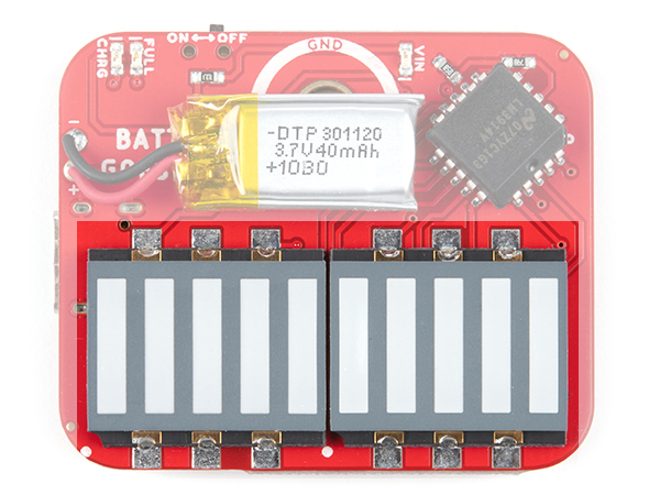
Of course, this board would not be called the MyoWare 2.0 LED Shield if it did not have the large segment LEDs. The bar graph lights up corresponding to the level of the muscle signal measured. The minimum is closest to the dot bar driver IC. As there is more muscle activity, the voltage will increase from the ENV pin. As a result, the LEDs will continue to light up until the last one on the other side is lit. The LEDs are bright enough to be seen in full light, but really glow nice in low light.
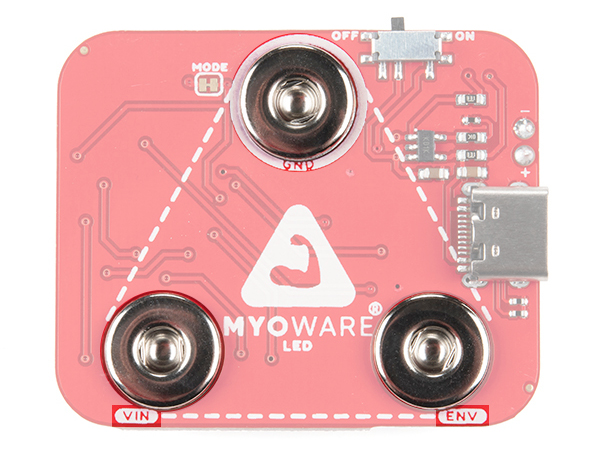
Snap Connectors
The board includes three female snap connectors to easily stack on top of the MyoWare 2.0 Muscle Sensor:
- GND - Ground for power.
- VIN - Voltage input for power. This voltage depends on how much the LiPo battery is charged up. When plugged in to a power source for charging, the charge IC may start charging the LiPo battery and will be about 4.2V. For safety reasons, we recommend that users always disconnect this shield from the sensor while charging the battery.
- ENV - Envelope signal ranging between 0-VIN. Connect this to an ADC on your microcontroller.
Jumper
The board includes one jumper for the MODE that is closed by default. The MODE is wired directly to LM3914 Dot/Bar Driver's V+ pin for bar graph mode. In this mode, the LED segments will continue to light up based on the magnitude of the muscle signal until the last one on the other side is lit. Opening the MODE jumper will turn the board into dot mode. When dot mode is enabled, a leading LED bar (i.e. "dot") will light up and traverse the segments. Any trailing LEDs behind it will be turned off instead of filling in with light. For more information on modifying the jumpers, check out our tutorial on working with jumper pads and PCB traces.
Board Dimensions
The shield uses the MyoWare 2.0 Muscle Sensor form factor. The board dimension is different than the other boards: 46.15mm x 38.00mm (1.82” x 1.50”).
