Getting Started with the MyoWare® 2.0 Muscle Sensor Ecosystem
 QCPete,
  bboyho
Hardware Hookup
Advancer Technologies has provided a Quick Start and Advanced Guide for the MyoWare 2.0 Muscle Sensor. Feel free to check them out with this guide.
Selecting a Muscle Group
Select a muscle group to place the MyoWare 2.0 Muscle Sensor. Placement of the sensor is critical when measuring the muscle activity. You will need to connect the MID electrode to the middle of the muscle body with the END electrode lined up in the direction of the muscle length. The REF electrode will be adjacent to the muscle body.
We'll be using the forearm as an example. You can connect the sensor to any muscle group as long as orient the sensor's electrodes with respect to the target muscle as explained above. Note that the muscle group shown in the image below are not to scale.
For more other muscle groups, check out the MyoWare 2.0 Advanced Guide. Make sure to zoom in on the image for a closer look at the muscle group. The positions shown in the image are approximate.

Preparing the Skin
Grab an alcohol swab to clean the skin where the MyoWare 2.0 Muscle Sensor will be placed. Cleaning the skin with soap can leave a residue on the skin and should be avoided.

Clean the skin where the EMG pads will stick using an alcohol swab. A cotton ball soaked in isopropyl alcohol is also sufficient to remove any oils or surface contaminants on the skin. Allow the isopropyl alcohol to evaporate before sticking the EMG pads on the skin
Stacking Shields
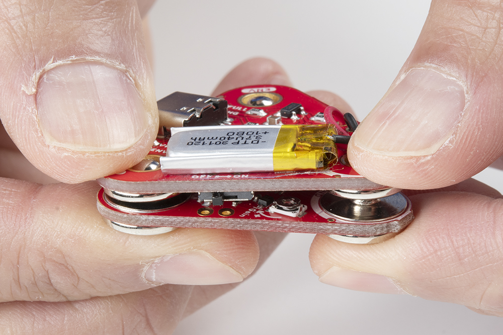
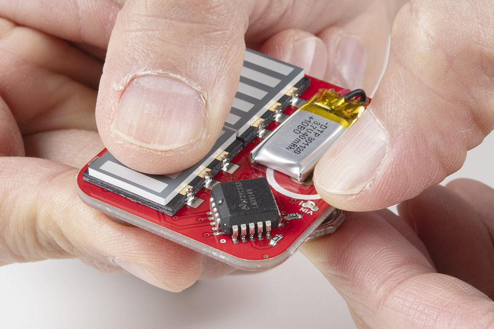
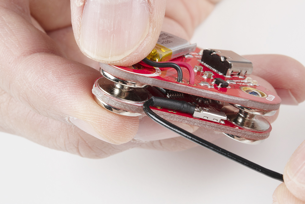
Since the shields are keyed, there's only one way to stack the boards together! Just look for the snap connector labeled as GND or REF. Align the snap connectors. Make sure the power switch is flipped to the OFF position for shields.
Push down on the snap connectors using your thumb and index finger. Make sure to avoid pressing down on the built-in LiPo battery.
 |
 |
Connecting to a Muscle Group
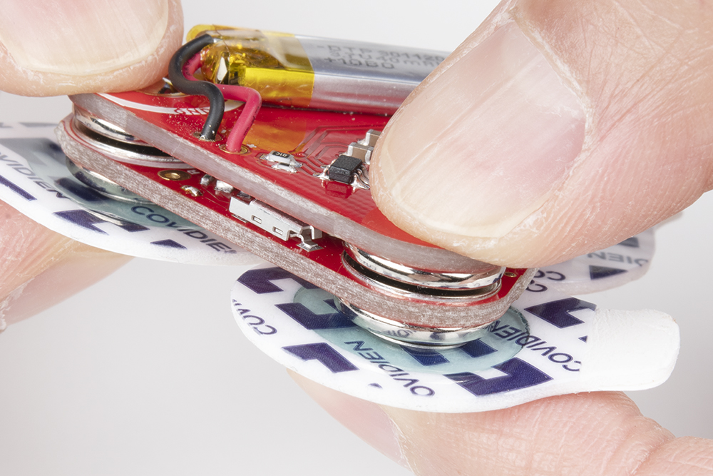
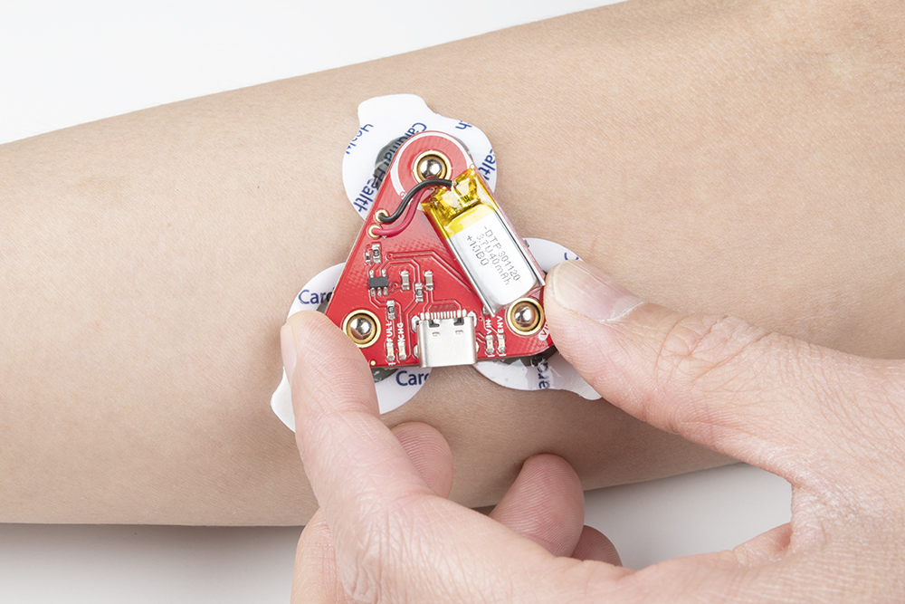
Snap the EMG pads to the bottom of the MyoWare 2.0 Muscle Sensor. For users using the MyoWare 2.0 Cable Shield, you'll be snapping it to the sensor cable's snap connectors.
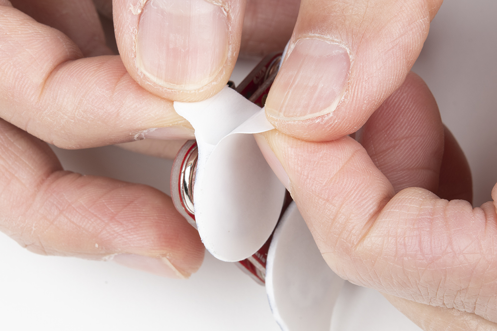
Peel and carefully remove the backs of the electrodes to expose the adhesive.
Attach the pads to the target muscle. In this case, we are using our right forearm.
Ensure that power is disconnected when stacking shields on the top side of the MyoWare 2.0 Muscle Sensor. Once everything is connected, flip the power switch to the ON position on the Power Shield or LED Shield. For users connecting the sensor to an Arduino and computer, check to make sure that your computer is not connected to the wall outlet. Then flip the power switch to the ON position on the Link Shield.
Connecting Shields to the Arduino R3 Development Board
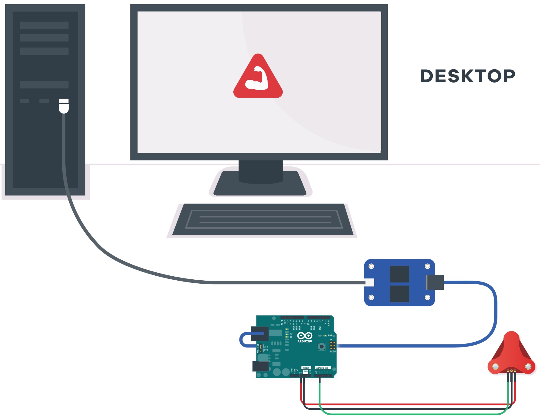
Image Courtesy of Advancer Technologies taken from the MyoWare 2.0 Quick Start Guide
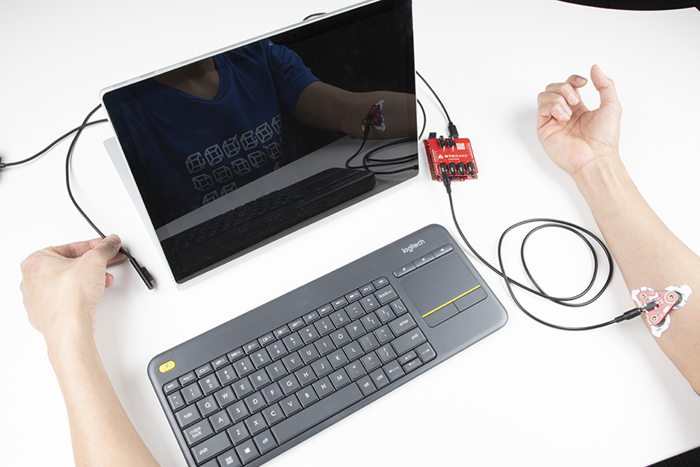
If you do not have a USB isolator, try using a laptop running on battery power and ensure that you are not connecting the laptop to a wall outlet.

Image Courtesy of Advancer Technologies taken from the MyoWare 2.0 Quick Start Guide
We also recommend using a wireless keyboard and mouse when programming in Arduino. The muscle sensor is sensitive enough that it can also pick up a signal from the trackpad or keyboard on your laptop when running on power. As a result, the muscle sensor will have false readings and the Arduino's analog pin will read high.
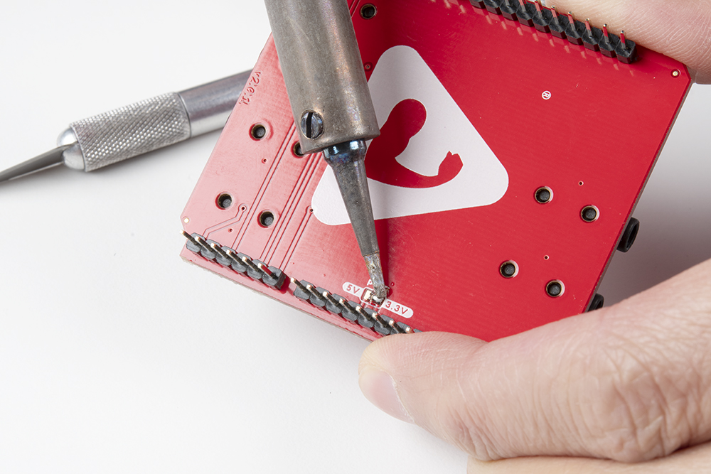
For users using a 3.3V Arduino, we recommend adjusting the PWR jumper by cutting the default trace and adding a solder jumper between the center pad and the 3.3V side. For users using a 5V Arduino, you can leave the jumper connected to the 5V side. For more information on modifying the jumpers, check out our tutorial on working with jumper pads and PCB traces.
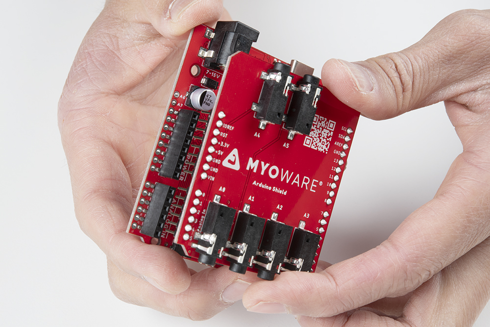
Stack the Arduino Shield on your chosen development board with the Arduino Uno R3 footprint.
Insert the TRS cable between the MyoWare 2.0 Link Shield and Arduino Shield's TRS connector. In this case, we will be using the connector labeled as A0. Make sure to adjust the code when using the other channels.
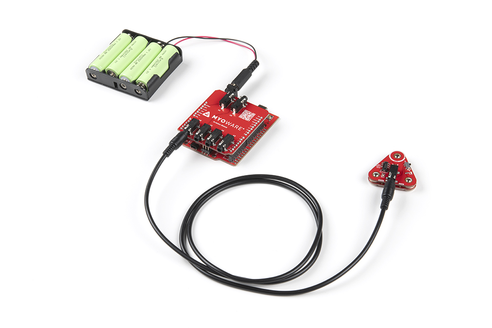
For remote applications, we recommend using a battery pack. In this case, we used AA batteries (NiMH) and a 4xAA battery pack to power the system.
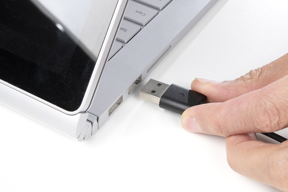
Make sure to remove the power supply from your computer before connecting your Arduino with the MyoWare 2.0 Muscle Sensor to your USB port. This is to prevent noise and safeguard against electrical shock when connected to the power grid. This includes any computer docks and external monitors.
When ready, insert the USB cable between your Arduino and computer's USB port.
For users transmitting sensor data via Bluetooth, attach a battery pack to the RedBoard Artemis acting as the Bluetooth peripheral device. This is assuming that it has the Bluetooth peripheral example code uploaded. Connect the RedBoard Artemis acting as the Bluetooth central device to your computer's USB port. Since the Bluetooth peripheral device is disconnected, you could connect your laptop to a power supply since the MyoWare 2.0 Muscle Sensor is not connected to the main outlet. You just need to make sure to unplug the power supply every time you need to reprogram the RedBoard Artemis acting as the peripheral device.
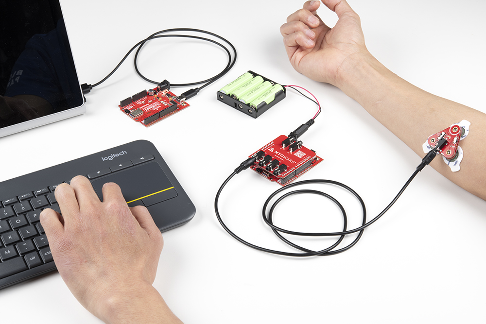
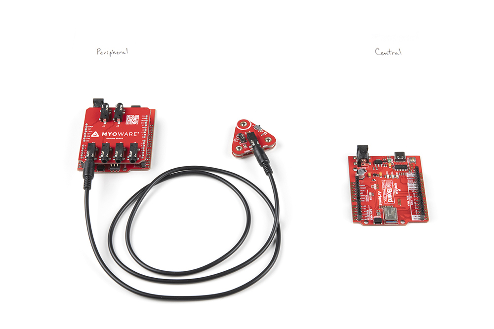
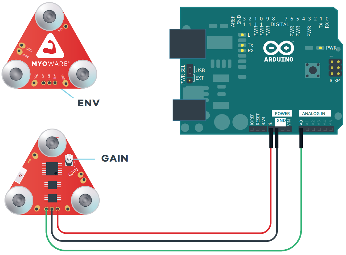
Image Courtesy of Advancer Technologies taken from the MyoWare 2.0 Advanced Guide
Connecting Wireless Shield to the Muscle Sensor
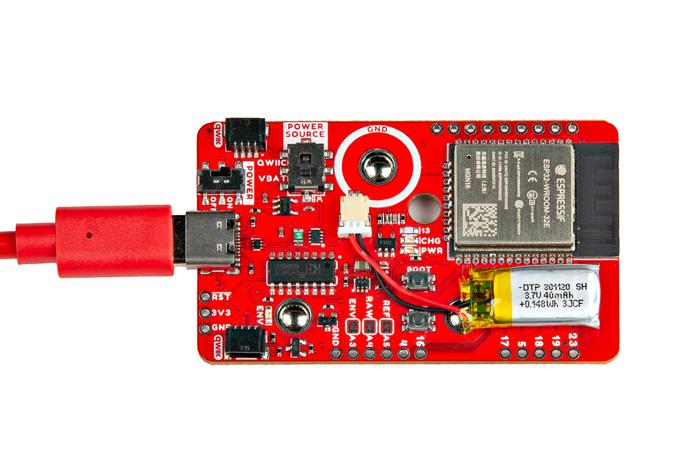
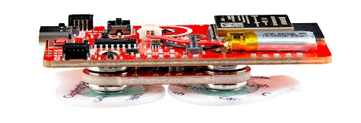
When uploading new code to the Wireless Shield, you will need to connect a USB cable between the MyoWare 2.0 Wireless Shield and your computer's USB port. Select the POWER SOURCE on the Wireless Shield (in this case, we used the built-in LiPo battery so the switch was flipped toward the VBAT). When ready, flip the switch for the POWER to the ON position to begin uploading the modified peripheral code (i.e. MyoWareBLEPeripheral.ino) using the Arduino IDE. This is also how you would charge the built-in LiPo battery.
After uploading code, flip the POWER switch to the OFF position. Stack the shield on top of the MyoWare 2.0 Muscle Sensor similar to the Power Shield or LED Shield. Then attach the EMG pads to the bottom of the board.
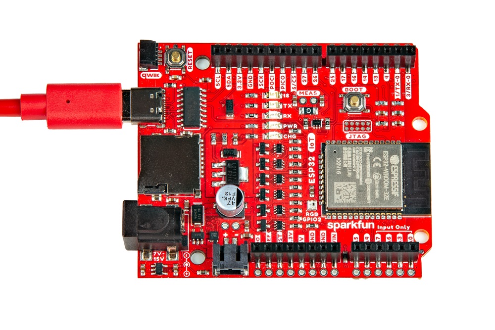
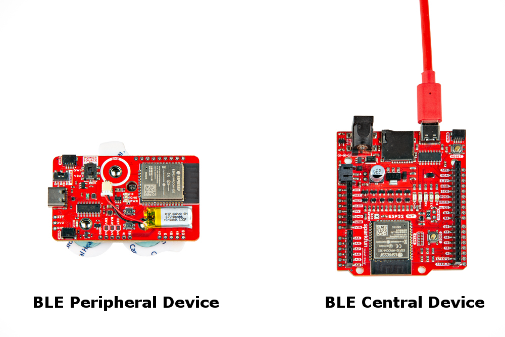
Connect a compatible ESP32 development board to your computer's USB port. This will act as a Bluetooth central device. When ready, upload the code for the Central Device (i.e. MyoWareBLECentral.ino) to the ESP32. In this case, we used the IoT RedBoard - ESP32.
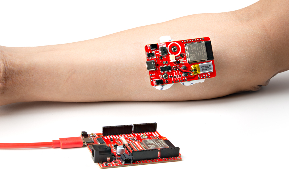
At this point, your setup should look similar to the following before attaching to the Muscle Sensor to a muscle group. To keep track of what board is the peripheral and central, try labeling the boards with a Sharpie or label maker.
Once a muscle group has been chosen, prepare the skin with alcohol wipes, remove the backs of the electrodes, and attach the stack to a muscle group. In this case, we used the forearm.
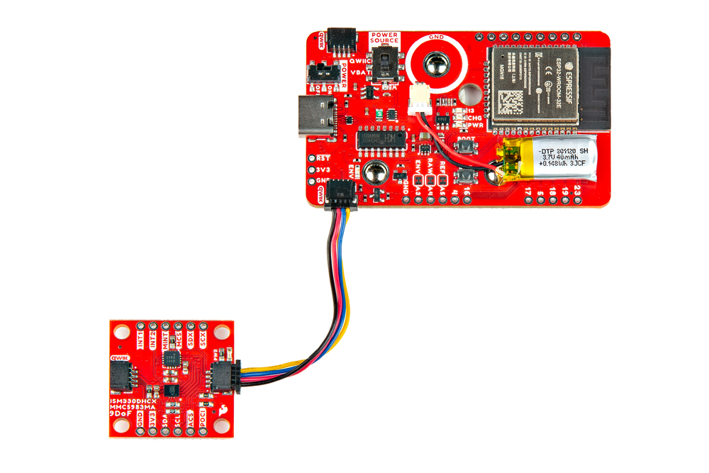
Connecting a Qwiic Enabled Device to the Wireless Shield
For users that are interested in connecting another Qwiic-enabled device, you will just need to insert a Qwiic cable between the two boards. You will just need to make an enclosure or find a way to mount the Qwiic-enabled device.
External Cable
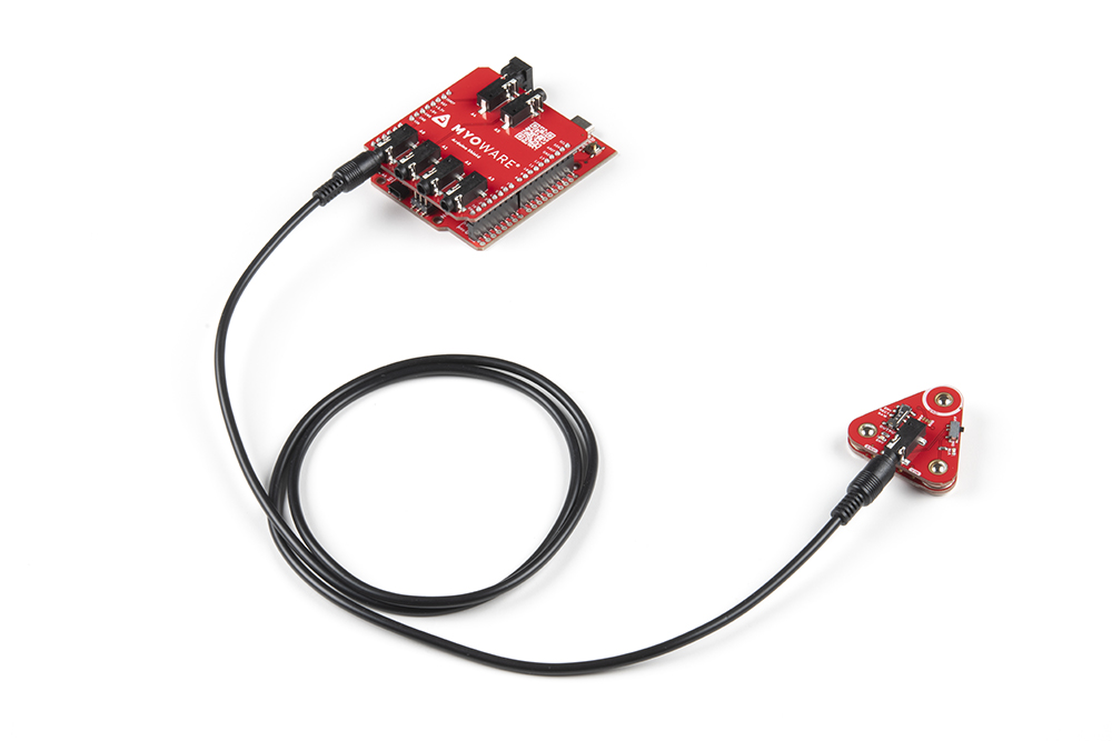
For muscles that require you to mount the sensor pads away from the sensor, snap the MyoWare 2.0 Cable Shield on the bottom of the MyoWare 2.0 Muscle Sensor. Then insert the sensor cable into the 3.5mm TRS connector.
Attach the EMG pads to the snap connectors. After cleaning the skin and selecting the muscle, peel and remove the backs of the electrodes to expose the adhesive. Then attach the pads to the target muscle group based on the MID, END, and REF.
| Snap Connector | TRS Pin | Electrode Pin [CAB-12970] |
|---|---|---|
| Reference [REF] | Sleeve | Black |
| End [END] | Ring | Blue |
| Middle [MID] | Tip | Red |
Reference Cable
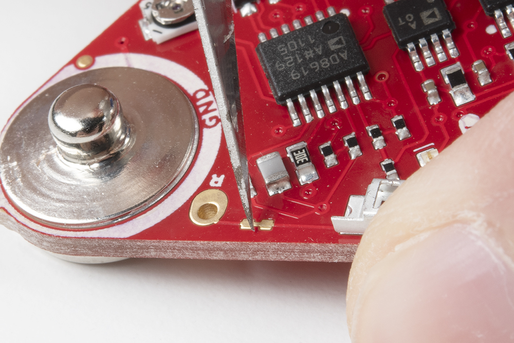
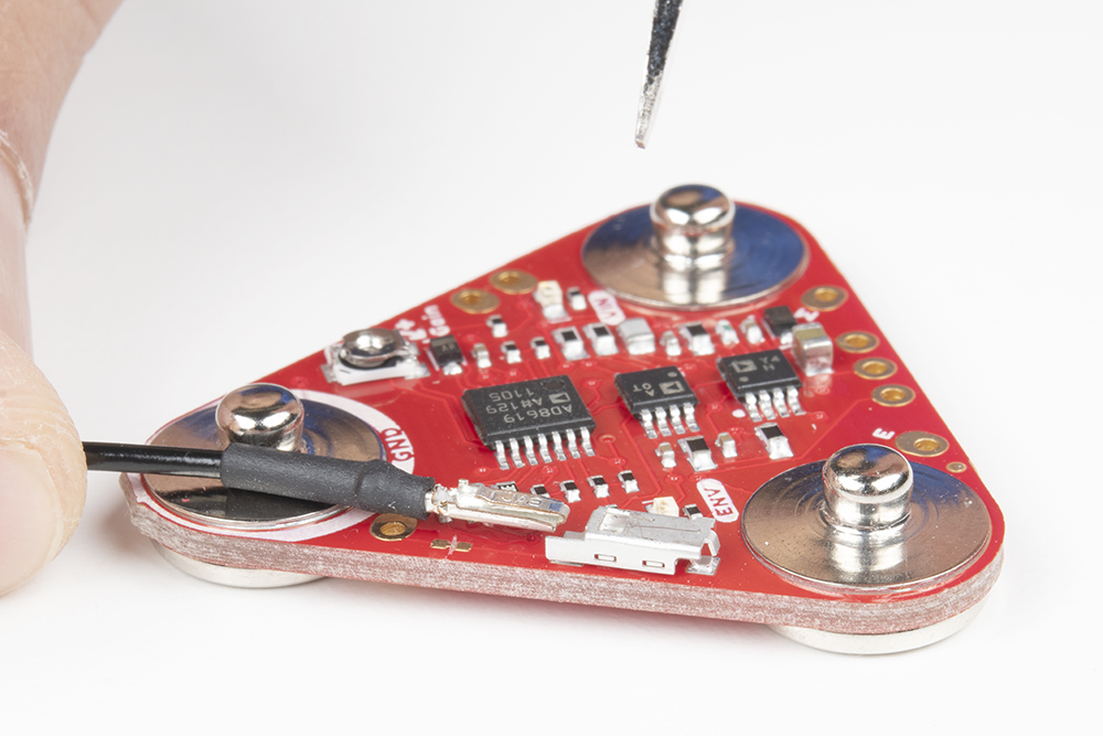
With a hobby knife, slice the reference jumper pad closest to the GND pin. There are traces near the jumper so you will need to make sure to avoid cutting traces that are adjacent to jumper pad. For more information on modifying the jumpers, check out our tutorial on working with jumper pads and PCB traces.
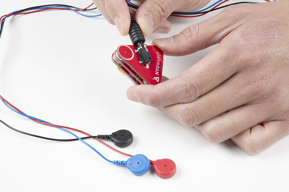
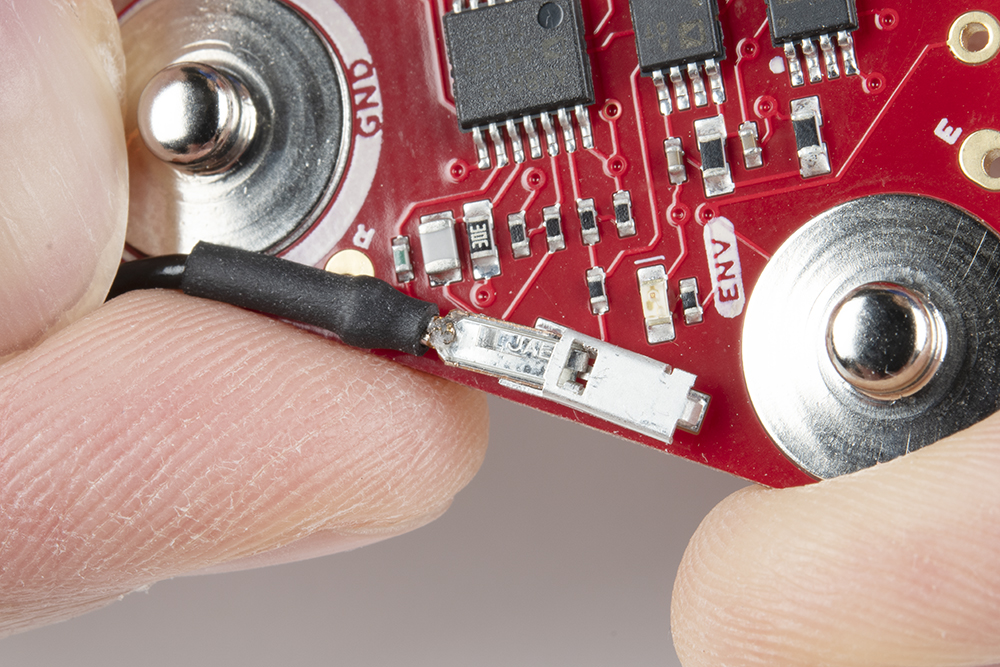
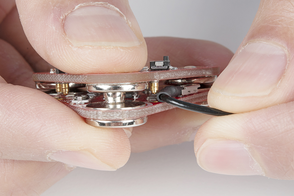
Then insert the reference cable into the MyoWare 2.0 Muscle Sensor, slide the pin into the housing with the tab facing away from the board.
When stacking a shield on top of the MyoWare 2.0 Muscle Sensor, make sure carefully pull the cable away from the shield's snap pin.
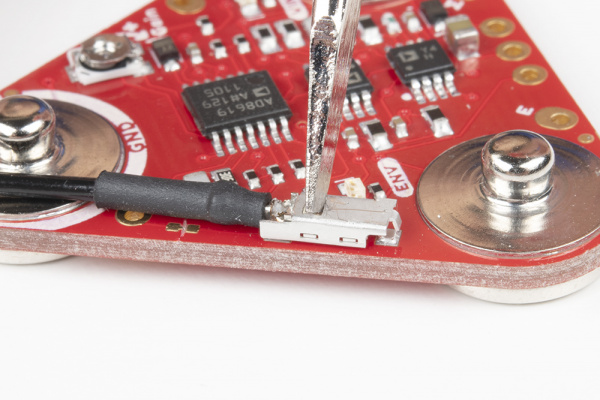
To remove the reference cable, push the tab into the housing with the end of a flathead screwdriver and gently pull the pin out of the housing.
 |
 |
To close the jumper pad, add a small amount of solder on the jumper pad.
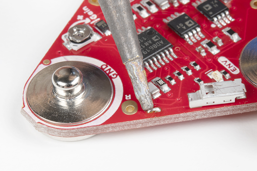
Disconnecting the MyoWare Shield
When prototyping, you will want to test out different shields or you may need to adjust the trim pot. To remove the boards, you will need a flathead screwdriver. With power off, insert the flathead between the snap connectors and ensure that there are no components in the way of the flathead. Gently slide the flathead between the snap connectors.
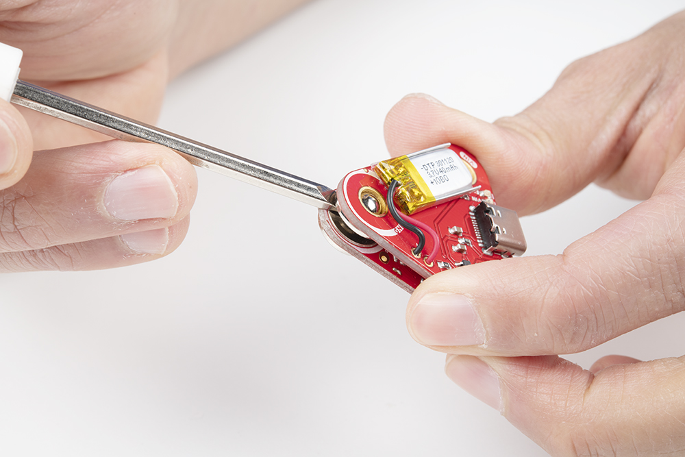
Angle the flathead against the connectors until the boards disconnect.

With one side disconnected, pull the boards away from each other so that the other two snap connectors disconnect.