Getting Started with the MyoWare® 2.0 Muscle Sensor Ecosystem
MyoWare 2.0 Link Shield
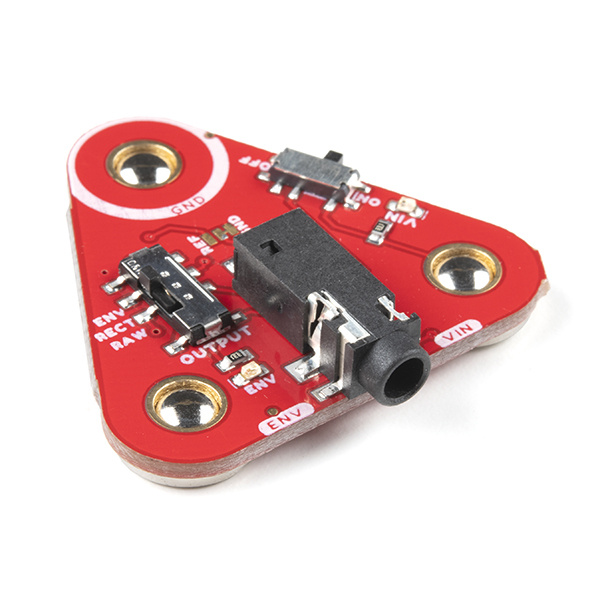
The MyoWare 2.0 Link Shield is designed to easily connect a MyoWare 2.0 Muscle Sensor to your Arduino microcontroller. The shield provides a 3.5mm TRS jack so that you can use a 3.5mm TRS-to-TRS cable to link the boards together. The MyoWare 2.0 Link Shield is equipped with snap connectors on the board so you can easily stack it to the top side of the MyoWare 2.0 Muscle Sensor. You'll need the MyoWare 2.0 Arduino Shield and a development board with the Arduino Uno R3 footprint to link each MyoWare 2.0 Muscle Sensor and Link Shield stack.
Hardware Overview
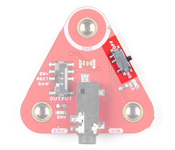
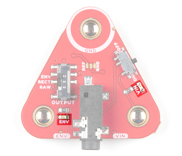
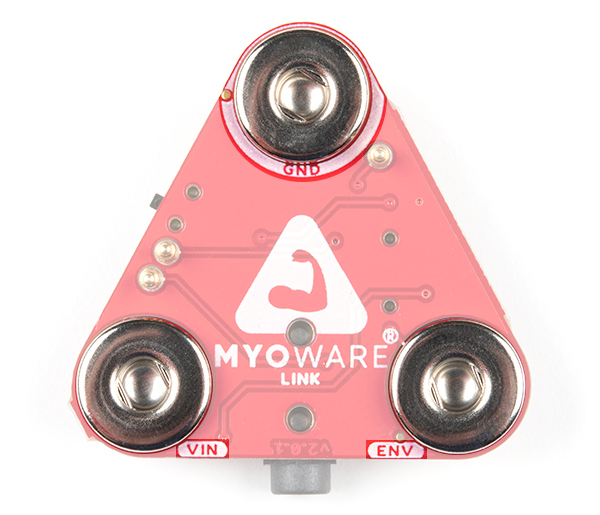
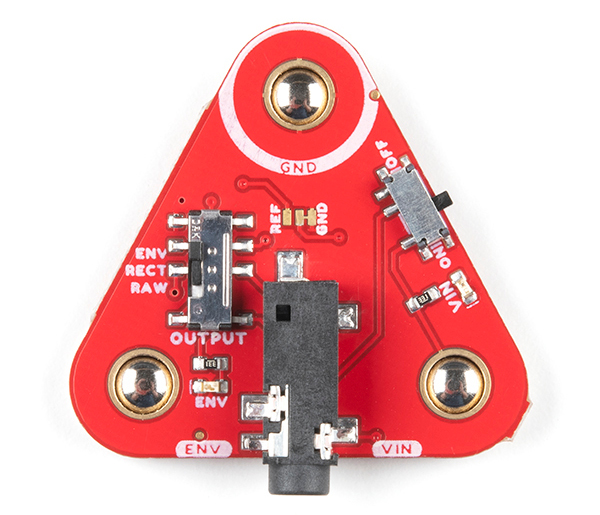
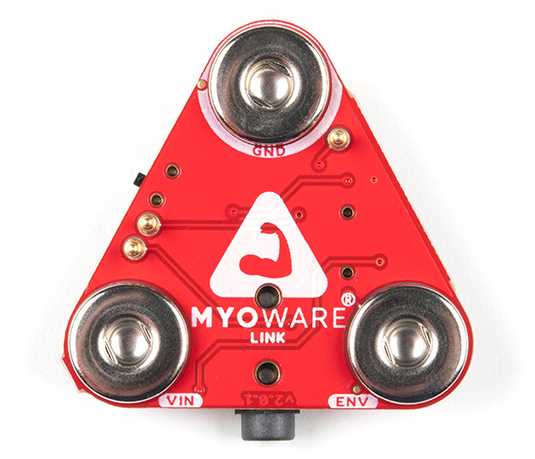
The top side of the board has the TRS connector, power and output switches. The bottom side of the board includes the female snap connectors.
 |
 |
| Top Side | Bottom Side |
Power Switch
The power switch turns MyoWare 2.0 Muscle Sensor on and off. Power is provided by your Arduino and the Arduino Shield. By default, power is set to 5V on the Arduino Shield. The ring pin of your TRS-to-TRS cable will connect the 5V to VIN when the switch is flipped to the ON position.
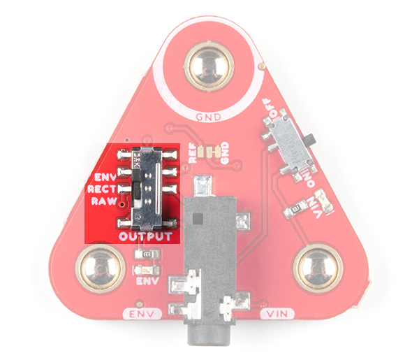
Output Switch
The OUTPUT switch selects the signal to provide for the Arduino's analog input.
- ENV - Envelope output.
- REC - Rectified output.
- RAW - Raw output.
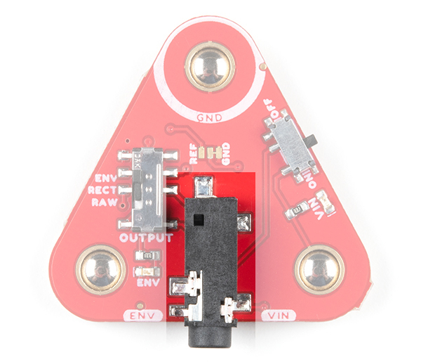
3.5mm TRS Connector
The 3.5mm TRS connector is connected to the following pins.
| Pinout | TRS Pin |
|---|---|
| Ground [GND] | Sleeve |
| Voltage Input [VIN] | Ring |
| ENV/RECT/RAW [OUTPUT] | Tip |
LEDs
The board includes two LEDs.
- VIN - The VIN LED lights up when the power switch is flipped to the ON position to indicate when the board is providing power for the MyoWare 2.0 Muscle Sensor through the VIN snap pin.
- ENV - The ENV pin lights up when there is activity from the MyoWare 2.0 Muscle Sensor's ENV pin.
Snap Connectors
The board includes three female snap connectors to easily stack on top of the MyoWare 2.0 Muscle Sensor:
- GND - Ground for power.
- VIN - Voltage input for power. This voltage depends on the the the jumper that was set on the MyoWare 2.0 Arduino Shield. This voltage can be 5V (default) or 3.3V depending on the position of the PWR jumper on the MyoWare 2.0 Arduino Shield.
- ENV - Envelope signal ranging between 0-VIN. Connect this to an ADC on your microcontroller.
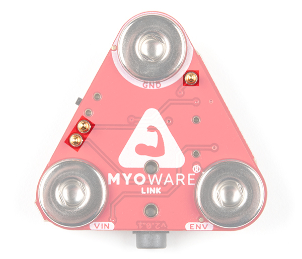
Pogo Pins
There are three pogo pins on the bottom of the board. These have a much lower profile than the other pogo pins that you may have seen in our storefront. These connect to the MyoWare 2.0 Muscle Sensor's PTH pads. Note that the MyoWare 2.0 Link Shield does not have any labels for the pins. The pogo pin closest to the GND snap connector is the reference pin. The pogo pin just next to the switch is the rectified output pin. The pogo pin just above the VIN snap connector is the raw output.
- REF - Reference pin.
- RECT - Rectified output pin.
- RAW - Raw output pin.
 |
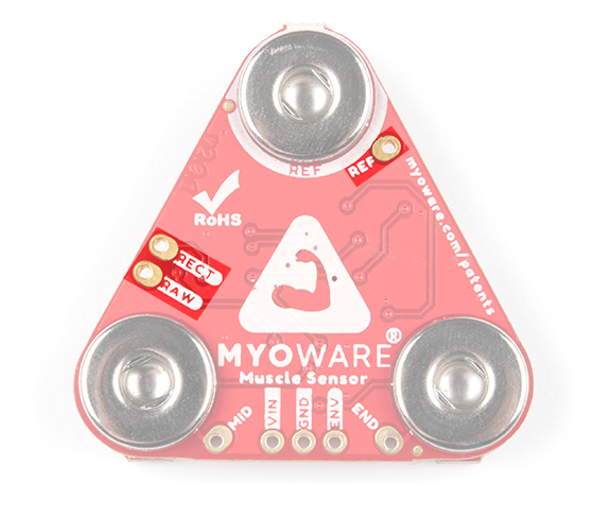 |
| Pogo Pins on the MyoWare 2.0 Link Shield | PTH Pads on the MyoWare 2.0 Muscle Sensor |
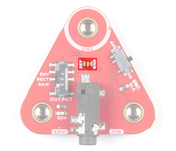
Jumper
The board includes a 3-way jumper on the top of the board. The point of this jumper is to allow users to change the relative ground point for the output and Arduino. By default, the RAW output will be centered around VIN/2, which is what REF is. Some users might want to change this so that it is centered around 0V, which would require changing the relative ground point to REF. Cutting the trace connected to GND and adding a solder jumper between the REF and center pad will connect the REF pogo pin to the muscle sensor's REF. For more information on modifying the jumpers, check out our tutorial on working with jumper pads and PCB traces.
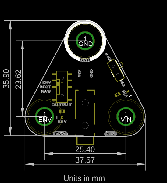
Board Dimensions
The shield uses the MyoWare 2.0 Muscle Sensor form factor and has board dimensions of 37.57mm x 35.90mm (1.48” x 1.41”).
