Getting Started with the MyoWare® 2.0 Muscle Sensor Ecosystem
 QCPete,
  bboyho
 MyoWare 2.0 Wireless Shield
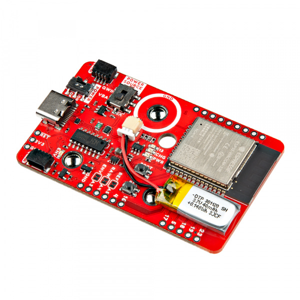
The MyoWare® 2.0 Wireless Shield is designed to take in readings from the MyoWare 2.0 Muscle Sensor and wirelessly transmit sensor data with the ESP32-WROOM! This shield also includes a built-in LiPo battery to remotely power both the muscle sensor and the ESP32 module. The Wireless Shield is equipped with snap connectors and low profile pogo pins on the board so you can easily stack it on the top side of the MyoWare 2.0 Muscle Sensor. Simply select a Power Source and flip the power switch to the ON position to give the sensor all the power it needs to work its myoelectric magic.
Hardware Overview
 |
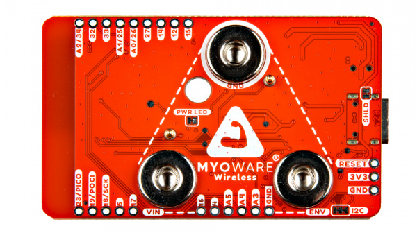 |
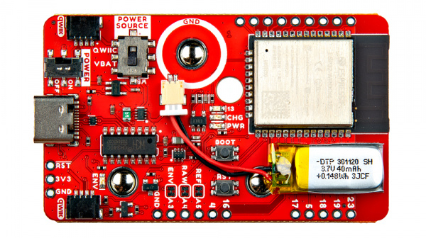
| Top Side | Bottom Side |
Power
There are a variety of power and power-related nets broken out to connectors and through hole pads. How the Wireless shield is powered will depend on the configuration of the switches. Let's take a look at the options below.
Power USB
A USB type C connector is included to power and program the ESP32. There are ESD protection diodes connected to the USB's data lines, a resettable fuse, and ideal diodes for reverse polarity protection on the USB and battery nets. You can also view serial data between the microcontroller and computer. When connected to the MyoWare 2.0 Muscle Sensor, however, we recommend sending data wirelessly to reduce the chance of introducing noise to the system and safeguard against electrical shock from the power grid. The USB connector is also used to charge the LiPo battery.
You will need to make sure that the switches are flipped to the proper sides to power the ESP32. Check below about the switches for more information.
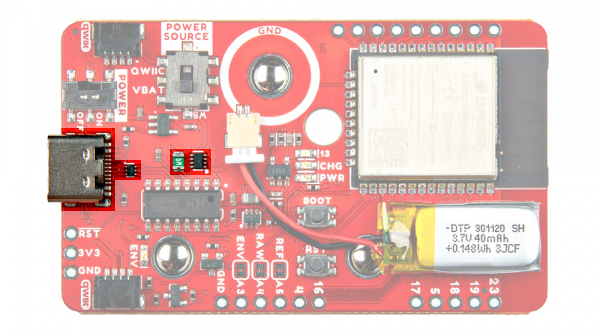
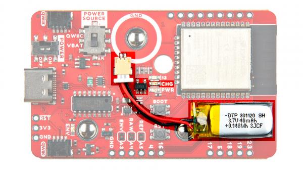
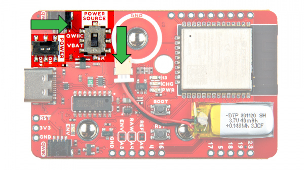
Power LiPo Battery
The board includes the MCP73831 LiPo charger IC (the little black IC with 5 pins) to safely charge a single cell, LiPo battery. In this case, the charge rate is set to about 40mA to charge the built-in 40mAh LiPo battery. Compared to other LiPo batteries on SparkFun's catalog, this one uses a smaller 2-pin, 1.00mm pitch JST-SH connector.
Single Cell LiPo Battery Care
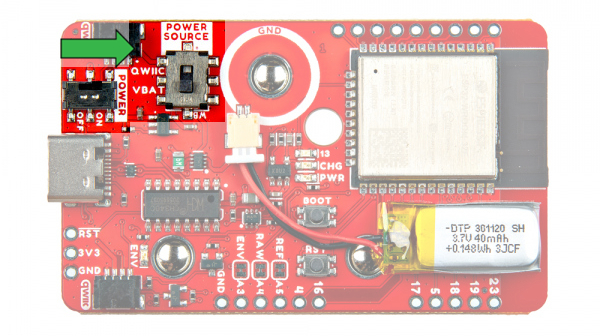
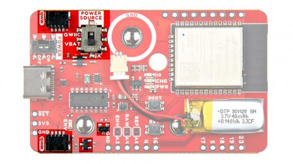
Switches
There are two switches on the board.
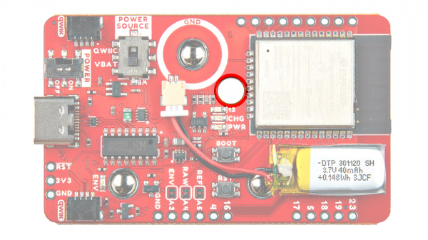
- Power Source
- Power ON/OFF

The Power Source is a triple pole, double throw (TPDT) switch. Flipping the switch to the VBAT position will connect the power source net to the 3.3V voltage regulator's output. This also connects the 3.3V voltage regulator's output to the Qwiic's 3.3V pin. Placing the switch in this position will connect the input of the voltage regulator to the upstream source (i.e. voltage from the USB or LiPo Battery).
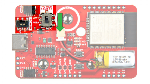
Flipping the switch to the QWIIC position will connect the power source net to the Qwiic's 3.3V pin. This also will disconnect the output from the 3.3V voltage regulator from everything. This allows you to power the MyoWare 2.0 Wireless Shield through the Qwiic connectors. Additionally, it will disconnect the input of the voltage regulator from the upstream source (i.e. voltage from the USB or LiPo Battery).
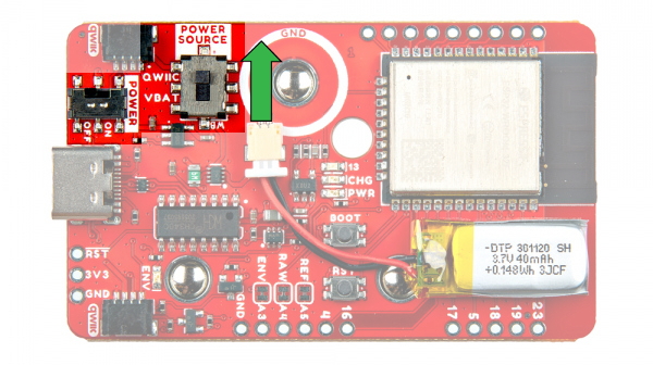
The switch labeled as Power ON/OFF, is a single pole, single throw (SPST) switch. Flipping the switch to the ON position, this connects the power source net to 3.3V net.
Flipping the switch to the OFF position will disconnect the power source net to 3.3V. This also disconnects the VREG input from any upstream sources. This removes power to the 3.3V voltage regulator regardless of the TPDT switch position.

3.3V
Voltage from the USB connector and LiPo battery is regulated down to 3.3V with the low power voltage regulator (RT9080). It can provide up to 600mA of output current for the system. The output of this voltage regulator will connect to the 3.3V PTH when the Power Source is flipped to the VBATT position. For users that decide to power the board through the Qwiic connector or PTH, you will need to flip the Power Source's switch to the QWIIC position and ensure that you are providing a regulated voltage of 3.3V. The snap connector on the bottom of the board is also connected to 3.3V. This will provide power to the MyoWare 2.0 Muscle Sensor.
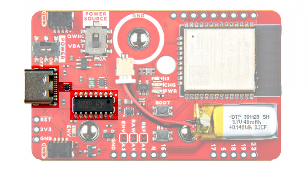
CH340 USB-to-Serial Converter
The board includes a CH340 USB-to-serial converter. The chip can be used to send serial data between the microcontroller's hardware serial UART and the computer's USB port. This chip is also used to upload code to the ESP32 using the Arduino IDE.
The driver should automatically install on most operating systems. However, there is a wide range of operating systems out there. You may need to install drivers the first time you connect the chip to your computer's USB port or when there are operating system updates. For more information, check out our How to Install CH340 Drivers Tutorial.
How to Install CH340 Drivers
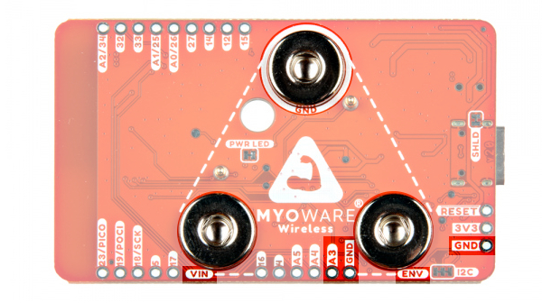
Snap Connectors
The board includes three female snap connectors to easily stack on top of the MyoWare 2.0 Muscle Sensor:
- GND - Ground for power.
- VIN - Voltage "output" for the MyoWare 2.0 Muscle Sensor. This is to match the VIN silkscreen on the MyoWare Muscle Sensor when stacking the shield. This is connected to the 3.3V depending on the position of the switches. For safety reasons, we recommend that users always disconnect this shield from the sensor while charging the battery.
- ENV - Envelope signal from the MyoWare 2.0 Muscle Sensor ranging between 0-VIN.This is connected to the ESP32's pin
39/A3.
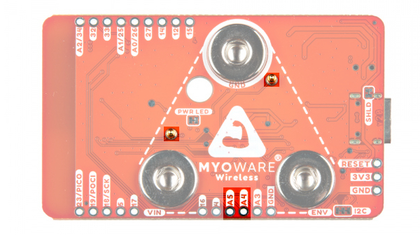
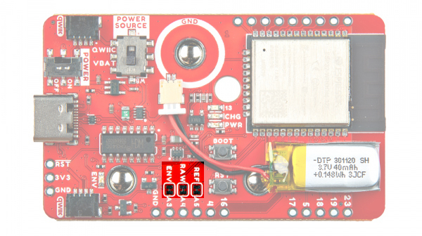
Pogo Pins
There are two pogo pins on the bottom of the board. These have a lower profile than other pogo pins that you may have seen in SparkFun's catalog . These connect to the MyoWare 2.0 Muscle Sensor's PTH pads. Note that MyoWare 2.0 Wireless Shield does not have any labels for these pogo pins. The pogo pin closest to the GND connector is the reference pin. The pogo pin by VIN is for the raw output.
- REF - Reference pin from the MyoWare 2.0 Muscle Sensor. This pogo pin connects to the ESP32's pin
35/A5. - RAW - Raw output pin from the MyoWare 2.0 Muscle Sensor. This pogo pin connects to the ESP32's pin
36/A4.
ESP32 Module
The "brains" of the board is the ESP32-WROOM module. Its pins are broken out to various components on the board, PTHs on the edge of the board, low profile pogo pins, and snap connectors.
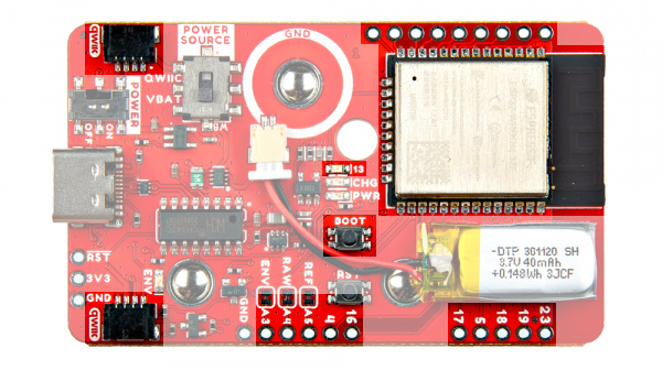 |
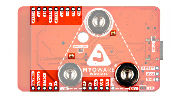 |
| ESP32 Broken Out to PTHs, Components | ESP32 Broken Out to PTHs, Snap Connectors, and Pogo Pins |
Reset and Boot Buttons
Each board includes two momentary buttons: one button for RESET and another for the bootloader mode (i.e. BOOT). Hitting the reset button will restart the ESP32 processor. The BOOT button is used to set the board in bootloader mode. Pressing down on the button as the board is powering up or when it is reset will set the board in bootloader mode. The BOOT button also acts as a general purpose button for user input and it is connected to the ESP32 on pin 0. If you decide to use the button, you will need to write a condition statement to do something after pressing the button.
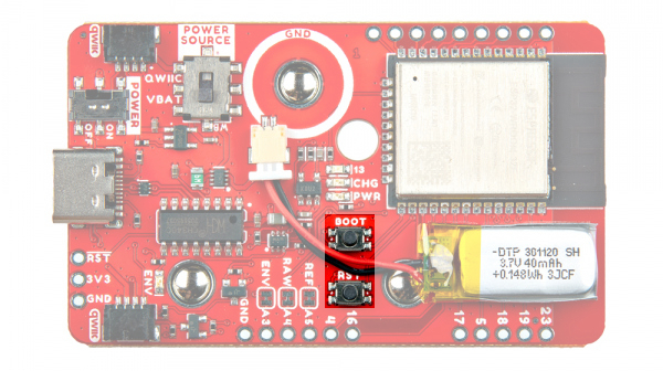
setup(). Need an idea for writing code for the general purpose button? We recommend looking at the SparkFun Inventor Kit V4.1 - Circuit 2B: Trumpet example! pinMode(10, INPUT_PULLUP);Qwiic and I2C
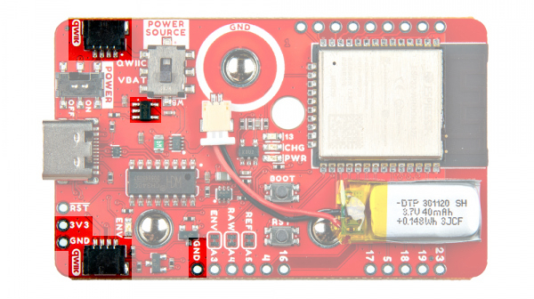
If you aren't familiar with the Qwiic Connection System, we recommend reading here for an overview.

The board includes two horizontal Qwiic connectors. These are the 4-pin, 1mm JST-SH style connectors. These are connected to the ESP32 module's I2C pins. The I2C data and clock lines are also tied to 2.2kΩ pull-up resistors (not highlighted in the image) and transistors for isolation. Make sure to select a power source for your Qwiic-enabled devices using the "Power Source" switch. This allows users to connect Qwiic-enabled devices to the board. Try adding a Qwiic enabled device to monitor the orientation of your arm!
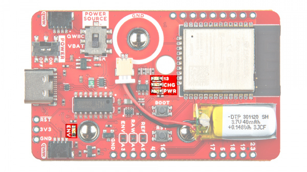
LEDs
There are four LEDs on the board:
- PWR - The PWR LED indicates when there is power on the board. This LED is connected to the 3.3V net. You can disable this LED by cutting the PWR jumper on the back of the board.
- CHG - The CHG LED can be used to get an indication of the charge status of your battery. Below is a table of other status indicators depending on the state of the charge IC.
| Charge State | LED status |
| No Battery | Floating (should be OFF, but may flicker) |
| Shutdown | Floating (should be OFF, but may flicker) |
| Charging | ON |
| Charge Complete | OFF |
- 13 - This is a general purpose LED and it is connected to pin
13. When using the default firmware, the LED will blink when not connected to a Bluetooth device. When the MyoWare 2.0 Wireless Shield is connected to a Bluetooth device, it will stay on. - ENV - The ENV pin lights up when there is activity from the MyoWare 2.0 Muscle Sensor's ENV pin.
Jumpers
There are jumpers available on the top and bottom of the board. The following three jumpers are on the top side of the board.
- REF - By default, this jumper connects the reference pin to the ESP32's pin
35/A5. Cut this to break the connection between the reference pin and the GPIO pin. - RAW - By default, this jumper connects to the raw EMG output to ESP32's pin
36/A4. Cut this to break the connection between the raw pin and the GPIO pin. - ENV - By default, this jumper connects to the envelope detector output to ESP32's pin
39/A3. Cut this to break the connection between the envelope pin and the GPIO pin.
On the bottom side, there are three sets of jumpers.
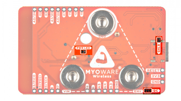
- SHLD - By default, the jumper is closed and located on the bottom side of the board. This jumper connects the USB Type C connector's shield pin to GND. Cut this to isolate the USB Type C connector's shield.
- PWR - By default, this jumper is closed and located on the bottom of the board. Cut this trace to disable the power LED that is connected to the output of the 3.3V voltage regulator.
- I2C - By default, this 3-pad jumper is closed by default and located on the bottom of the board. These connect the 2.2kΩ pull-up resistors to the I2C bus; if multiple devices are connected to the bus with the pull-up resistors enabled, the parallel equivalent resistance will create too strong of a pull-up for the bus to operate correctly. As a general rule of thumb, disable all but one pair of pull-up resistors if multiple devices are connected to the bus.
Through Hole
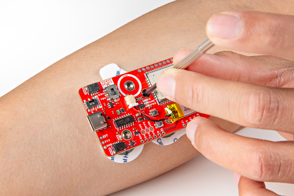
There is a small through hole on the MyoWare Wireless Shield for a precision Phillip's head. This is to manually adjust the potentiometer (trim pot) to change the gain of the envelope signal. As stated earlier in the hardware overview for the MyoWare 2.0 Muscle Sensor, the default gain should be sufficient for most applications. Take care when rotating the trim pot since it can be damaged by over rotating or applying too much pressure.
For users that need to adjust the default gain for a muscle group, we recommend turning the shield's POWER Switch to the OFF position and adjusting the gain down so that the maximum effort muscle contraction peaks just below VIN / 3.3V. Then turn the shield back on, connect the Bluetooth devices, and send the serial data wirelessly to a BLE central device to view the data.
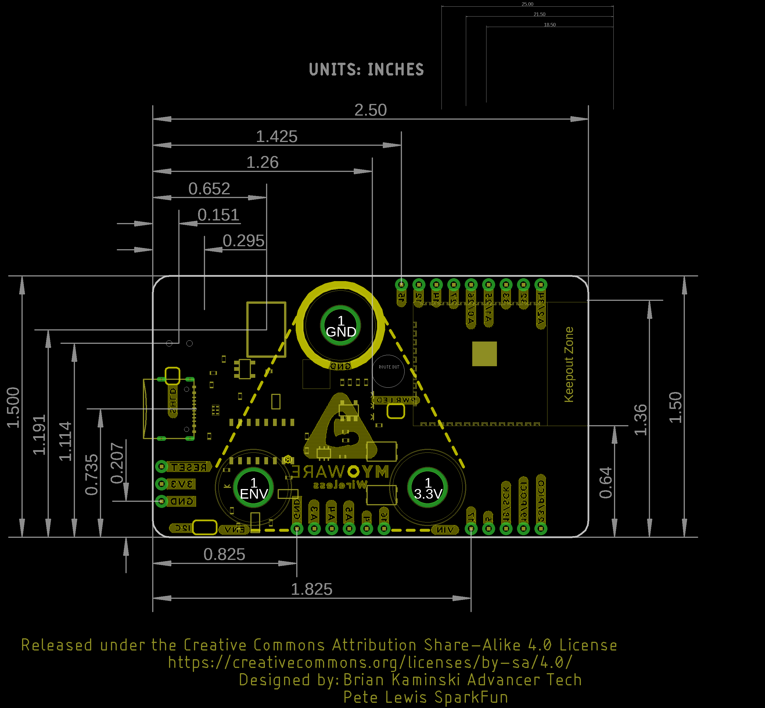
Board Dimensions
The board dimension is 63.5mm x 38.000mm (2.50" x 1.50").