SparkFun Inventor's Kit Experiment Guide - v4.1
 Joel_E_B,
  bboyho
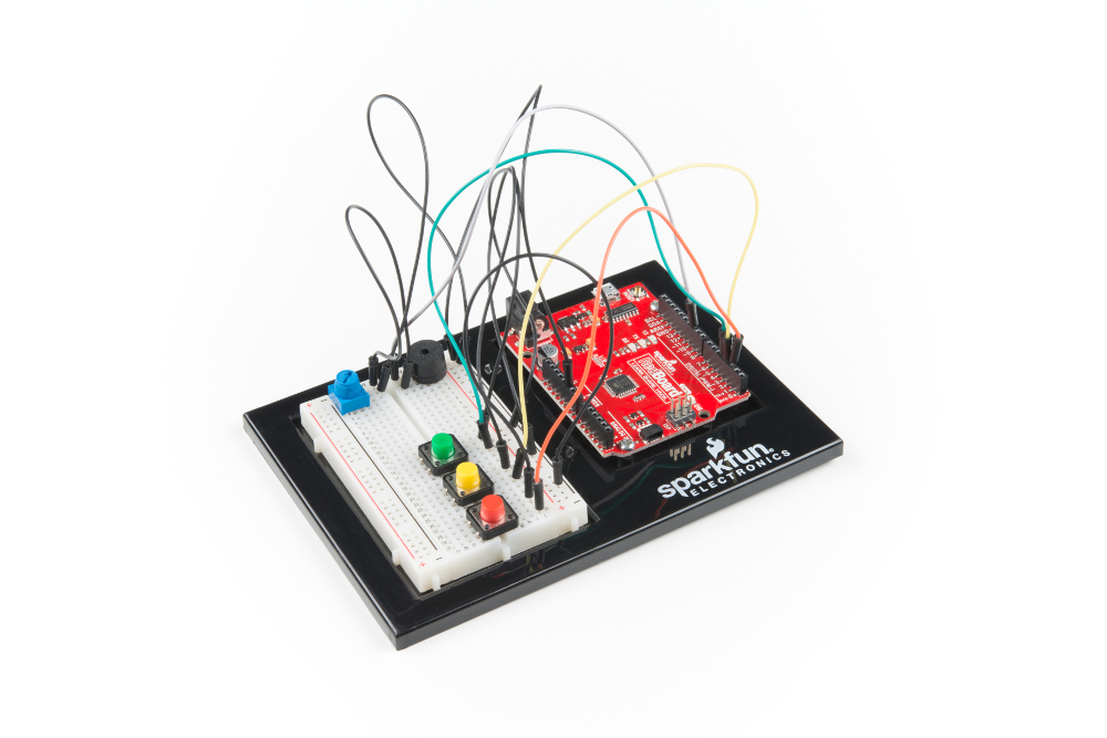
Circuit 2B: Digital Trumpet
Learn about digital inputs and buttons as you build your own digital trumpet!
Parts Needed
Grab the following quantities of each part listed to build this circuit:

New Components
Buttons
Buttons, also known as momentary switches, are switches that only remain in their on state as long as they’re being actuated, or pressed. Most often momentary switches are best used for intermittent user-input cases: reset button and keypad buttons. These switches have a nice, tactile, “clicky” feedback when you press them.
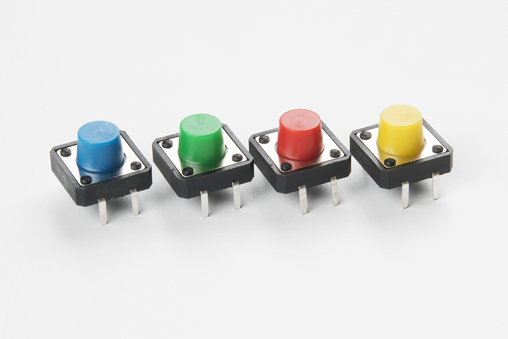
Note that the different colors are just aesthetic. All of the buttons included behave the same no matter their color.
New Concepts
Binary Number System
Number systems are the methods we use to represent numbers. We’ve all been mostly operating within the comfy confines of a base-10 number system, but there are many others. The base-2 system, otherwise known as binary, is common when dealing with computers and electronics. There are really only two ways to represent the state of anything: ON or OFF, HIGH or LOW, 1 or 0. And so, almost all electronics rely on a base-2 number system to store and manipulate numbers. The heavy reliance electronics places on binary numbers means it’s important to know how the base-2 number system works.
Digital Input
In circuit 1A, you worked with digital outputs. This circuit focuses on digital inputs. Digital inputs only care if something is in one of two states: TRUE or FALSE, HIGH or LOW, ON or OFF. Digital inputs are great for determining if a button has been pressed or if a switch has been flipped.
Pull-up Resistors
A pull-up resistor is a small circuit that holds the voltage HIGH (5V) on a pin until a button is pressed, pulling the voltage LOW (0V). The most common place you will see a pull-up resistor is when working with buttons. A pull-up resistor keeps the button in one state until it is pressed. The RedBoard has built-in pull-up resistors, but they can also be added to a circuit externally. This circuit uses the internal pull-up resistors, covered in more detail in the Code to Note section.
Hardware Hookup
Buttons are not polarized. However, they do merit a closer look. Buttons make momentary contact from one connection to another, so why are there four legs on each button? The answer is to provide more stability and support to the buttons in your breadboard circuit. Each row of legs is connected internally. When the button is pressed, one row connects to the other, making a connection between all four pins.
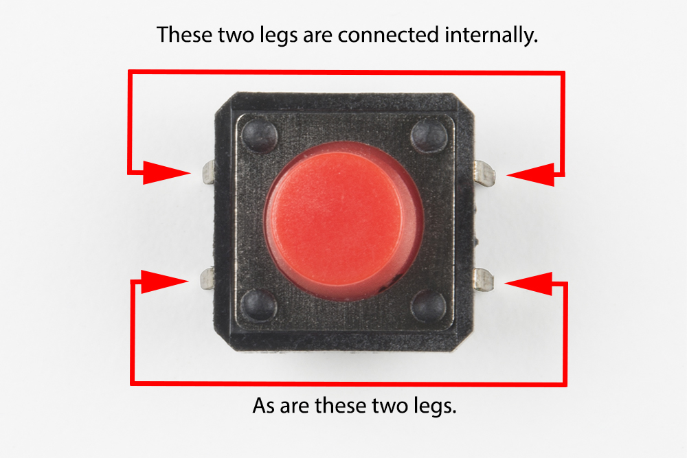
If the button's legs don't line up with the slots on the breadboard, rotate it 90 degrees.
Ready to start hooking everything up? Check out the circuit diagram and hookup table below to see how everything is connected.
Circuit Diagram
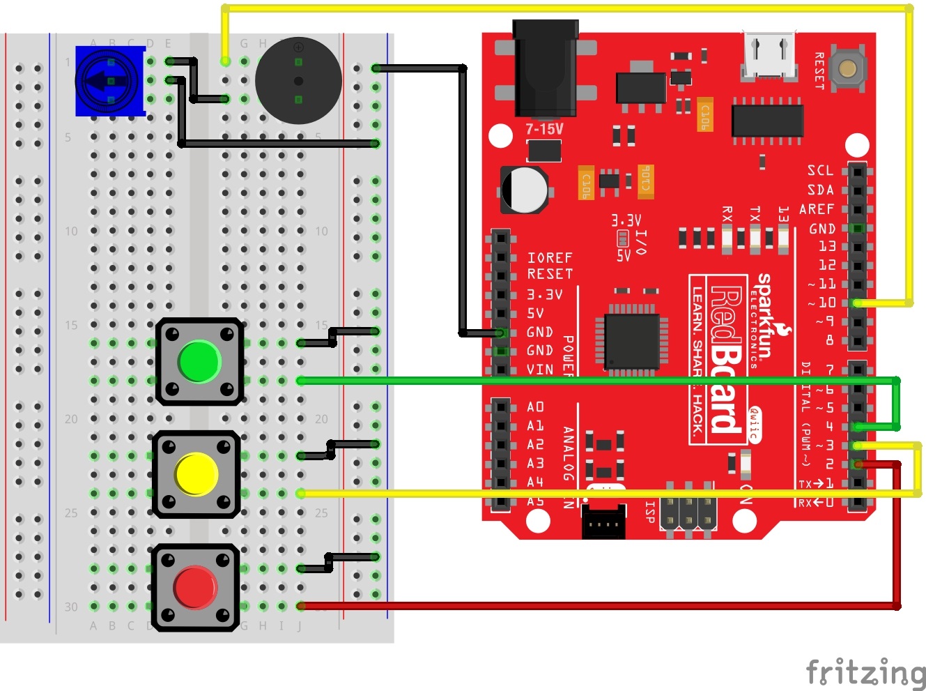
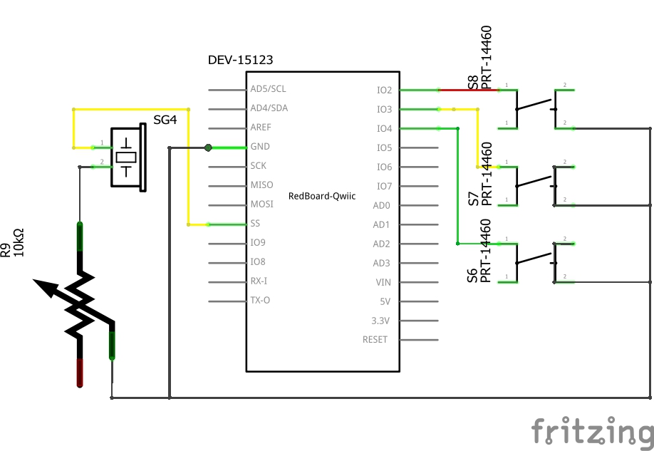
Having a hard time seeing the circuit? Click on the image for a closer look.
Hookup Table
| Component | RedBoard | Breadboard | Breadboard | Breadboard |
|---|---|---|---|---|
| Buzzer | J1 (Buzzer + ) | J3 (Buzzer - ) | ||
| Potentiometer | B1 | B2 | B3 | |
| Jumper Wire | GND | GND Rail ( - ) | ||
| Jumper Wire | Digital Pin 10 | F1 | ||
| Jumper Wire | E2 | GND Rail ( - ) | ||
| Jumper Wire | E1 | F3 | ||
| Push Button | D16/D18 | G16/G18 | ||
| Push Button | D22/D24 | G22/G24 | ||
| Push Button | D28/D30 | G28/G30 | ||
| Jumper Wire | Digital Pin 4 | J18 | ||
| Jumper Wire | Digital Pin 3 | J24 | ||
| Jumper Wire | Digital Pin 2 | J30 | ||
| Jumper Wire | J16 | GND Rail ( - ) | ||
| Jumper Wire | J22 | GND Rail ( - ) | ||
| Jumper Wire | J28 | GND Rail ( - ) |
Open the Sketch
To open the code, go to: File > Examples > SIK_Guide_Code-master > SIK_Circuit_2B-ButtonTrumpet
You can also copy and paste the following code into the Arduino IDE. Hit upload, and see what happens!
language:cpp
/*
  SparkFun Inventor’s Kit
  Circuit 2B-ButtonTrumpet

  Use 3 buttons plugged to play musical notes on a buzzer.

  This sketch was written by SparkFun Electronics, with lots of help from the Arduino community.
  This code is completely free for any use.

  View circuit diagram and instructions at: https://learn.sparkfun.com/tutorials/sparkfun-inventors-kit-experiment-guide---v41
  Download drawings and code at: https://github.com/sparkfun/SIK-Guide-Code
*/

//set the pins for the button and buzzer
int firstKeyPin = 2;
int secondKeyPin = 3;
int thirdKeyPin = 4;

int buzzerPin = 10;


void setup() {
  //set the button pins as inputs
  pinMode(firstKeyPin, INPUT_PULLUP);
  pinMode(secondKeyPin, INPUT_PULLUP);
  pinMode(thirdKeyPin, INPUT_PULLUP);

  //set the buzzer pin as an output
  pinMode(buzzerPin, OUTPUT);
}

void loop() {

  if (digitalRead(firstKeyPin) == LOW) {      //if the first key is pressed
    tone(buzzerPin, 262);                     //play the frequency for c
  }
  else if (digitalRead(secondKeyPin) == LOW) { //if the second key is pressed
    tone(buzzerPin, 330);                     //play the frequency for e
  }
  else if (digitalRead(thirdKeyPin) == LOW) { //if the third key is pressed
    tone(buzzerPin, 392);                     //play the frequency for g
  }
  else {
    noTone(buzzerPin);                        //if no key is pressed turn the buzzer off
  }
}

/*
  note  frequency
  c     262 Hz
  d     294 Hz
  e     330 Hz
  f     349 Hz
  g     392 Hz
  a     440 Hz
  b     494 Hz
  C     523 Hz
*/
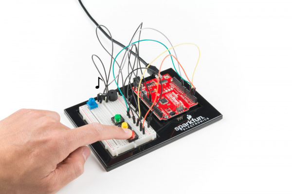
What You Should See
Different tones will play when you press different keys. Turning the potentiometer will adjust the volume.
Program Overview
- Check to see if the first button is pressed. a. If it is, play the frequency for c. b. If it isn’t, skip to the next else if statement.
- Check to see if the second button is pressed. a. If it is, play the frequency for e. b. If it isn’t, skip to the next else if statement.
- Check to see if the second button is pressed. a. If it is, play the frequency for g. b. If it isn’t, skip to the next else if statement.
- If none of the if statements are true a. Turn the buzzer off.
Code to Note
| Code | Description |
|---|---|
Internal Pull-Up Resistor:pinMode(firstKeyPin, INPUT_PULLUP); | To declare a standard input, use the line pinMode(pin_name, INPUT). If you would like to use one of the RedBoard's built-in pull-up 20kΩ resistors, it would look like this: pinMode(firstKeyPin, INPUT_PULLUP);. The advantage of external pull-ups is being able to choose a more exact value for the resistor. |
Digital Input:digitalRead(pin); | Check to see if an input pin is reading HIGH (5V) or LOW (0V). Returns TRUE (1) or FALSE (0) depending on the reading. |
Is Equal to:if(digitalRead(firstKeyPin) == LOW) | This is another logical operator. The 'is equal to' symbol (==) can be confusing. Two equals signs are equivalent to asking, "Are these two values equal to one another?" On the other hand, one equals sign in code is assigning a particular variable to a value. Don't forget to add the second equals sign if you are comparing two values. |
Coding Challenges
| Challenge | Description |
|---|---|
| Change the key of each button | Use the frequency table in the comment section at the end of the code to change the notes that each button plays. |
| Play more than three notes with if statements | By using combinations of buttons, you can play up to seven notes of the scale. You can do this in a few ways. To get more practice with if statements, try adding seven if statements and using the Boolean AND (&&) operator to represent all of the combinations of keys. |
| Play more than three notes with binary math | You can use a clever math equation to play more than three notes with your three keys. By multiplying each key by a different number, then adding up all of these numbers, you can make a math equation that produces a different number for each combination of keys. |
Troubleshooting
| Problem | Solution |
|---|---|
| The buzzer is too loud or too quiet | Turn the potentiometer to adjust the volume. |
| The RedBoard thinks one key is always pressed | Check your wiring. You may have ground and 5V backward if one or more buttons behave as though they're pressed all the time. |
| The buttons are not working | First, make sure that the wiring is correct. It is easy to misalign a wire with a button leg. Second, make sure that you have declared your buttons as inputs and have enabled the internal pull-up resistors with INPUT_PULLUP. |