Contributors:
 QCPete
,
 bboyho
 Introduction
Note: This tutorial is for the MyoWare 2 Muscle Sensor and its ecosystem. The MyoWare 2 Muscle Sensor is fully backwards compatible with the MyoWare 2.0 Muscle Sensor. If you are using the "V1" version (with only 2 snaps), please refer to the older
MyoWare Muscle Sensor V1 tutorial.
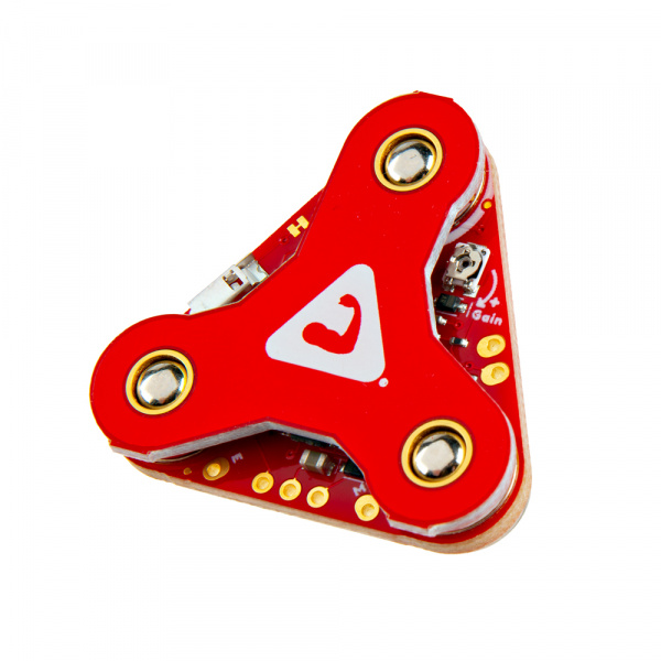
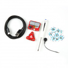
Using our muscles to control things is the way that most of us are accustomed to doing it. We push buttons, pull levers, move joysticks... but what if we could take the buttons, levers and joysticks out of the equation and control it with our muscles? The MyoWare 2.0 Muscle Sensor is an Arduino-compatible, all-in-one electromyography (EMG) sensor from Advancer Technologies that allows you to do just that! The MyoWare 2.0 Muscle Sensor has been redesigned from the ground up with a new, easy-to-use, compact design and upgraded with the latest and greatest chipset improving sensor performance and reliability. The innovative snap connector system eliminates the need to solder connections for the MyoWare 2.0 ecosystem. It's that easy: stick on a few electrodes (not included), read the output voltage and flex some muscles! In this tutorial, we will go over the features and related shields to connect the sensor to a muscle group.
Note: This sensor is not intended for use in the diagnosis of disease or other conditions, or in the cure, mitigation treatment, or prevention of disease, in a person or other animals.
DEV-27924
Using our muscles to control things is the way that most of us are accustomed to doing it. We push buttons, pull levers, move…
DEV-18425
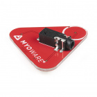
The MyoWare® 2.0 Link Shield is designed to easily connect a MyoWare® 2.0 Muscle Sensor to your Arduino via a 3.5mm TRS-to-…
DEV-21868
The MyoWare® 2.0 Power Shield is designed to easily power the MyoWare 2.0 Muscle Sensor remotely.
DEV-18426
The MyoWare® 2.0 Arduino Shield is designed to easily connect up to six MyoWare 2.0 Muscle Sensors and Link Shields using 3.…
DEV-18386
The MyoWare 2.0 Cable Shield allows you to test and use the MyoWare 2.0 Muscle Sensor without actually attaching the board to…
DEV-21869
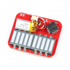
The MyoWare® 2.0 LED Shield is designed to display the magnitude of a target muscle's signal and power the MyoWare 2.0 Muscl…
Required Materials
To follow along with this tutorial, you will need the following materials. You may not need everything though depending on what you have. Add it to your cart, read through the guide, and adjust the cart as necessary. You'll need at least three biomedical sensor pads per muscle sensor each time you connect to a muscle group.
Note: The EMG pads are single use. You'll want to make sure that you have spare pads each time that you connect to a muscle group!
Minimum Parts
At a minimum, you will need the following parts to connect and power the muscle sensor. You can view the muscle signal from the ENV LED.
DEV-27924
Using our muscles to control things is the way that most of us are accustomed to doing it. We push buttons, pull levers, move…
SEN-12969
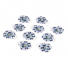
This is a 10 pack of Biomedical Sensor Pads, disposable electrodes that can be used to measure EEG, ECG and EMG levels. these…
DEV-21868
The MyoWare® 2.0 Power Shield is designed to easily power the MyoWare 2.0 Muscle Sensor remotely.
CAB-15424
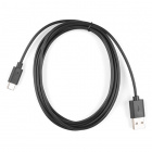
These 2m cables have minor modifications that allow them to be be plugged into their ports regardless of orientation on the U…
Note: Click below for a wishlist of the minimum parts.
Displaying the Magnitude of the Muscle Signal with LED Segments
You will need the following parts to connect and power the muscle sensor. You can view the magnitude of the muscle signal from the LED segments.
DEV-27924
Using our muscles to control things is the way that most of us are accustomed to doing it. We push buttons, pull levers, move…
SEN-12969
This is a 10 pack of Biomedical Sensor Pads, disposable electrodes that can be used to measure EEG, ECG and EMG levels. these…
CAB-15424
These 2m cables have minor modifications that allow them to be be plugged into their ports regardless of orientation on the U…
DEV-21869
The MyoWare® 2.0 LED Shield is designed to display the magnitude of a target muscle's signal and power the MyoWare 2.0 Muscl…
Note: Click below for a wishlist of the minimum parts.
Note: We also have the parts available in the
basic kit, which also includes the Reference Cable and a screw driver.
KIT-21267
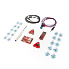
The MyoWare® 2.0 Muscle Sensor Basic Kit is an Arduino-compatible, EMG sensor kit that provides you with the essential board…
Retired
Connecting to an Arduino
You will need the following to connect an 5V Arduino without the need to solder any wires between boards. Connecting to an Arduino allows you to process sensor data to control a device or viewing the signal on the Arduino Serial Plotter.
DEV-27924
Using our muscles to control things is the way that most of us are accustomed to doing it. We push buttons, pull levers, move…
SEN-12969
This is a 10 pack of Biomedical Sensor Pads, disposable electrodes that can be used to measure EEG, ECG and EMG levels. these…
DEV-18158
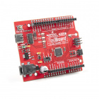
The RedBoard Plus is an Arduino-compatible development board that has everything you need in an Arduino Uno with extra perks …
DEV-18425
The MyoWare® 2.0 Link Shield is designed to easily connect a MyoWare® 2.0 Muscle Sensor to your Arduino via a 3.5mm TRS-to-…
DEV-18426
The MyoWare® 2.0 Arduino Shield is designed to easily connect up to six MyoWare 2.0 Muscle Sensors and Link Shields using 3.…
CAB-15424
These 2m cables have minor modifications that allow them to be be plugged into their ports regardless of orientation on the U…
CAB-18983
This cable has a standard TRS 3.5mm plug on both ends allowing for easy connections to any 3.5mm jack.
Note: You could also use an Arduino Uno as opposed to a RedBoard Plus. Just replace the RedBoard Plus and USB Cable.
DEV-11021
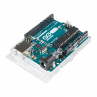
This is the new Arduino Uno R3. In addition to all the features of the previous board, the Uno now uses an ATmega16U2 instead…
CAB-00512
This is a standard issue USB 2.0 cable. This is the most common A to B Male/Male type peripheral cable, the kind that's usual…
Note: Click below for a wishlist of the minimum parts.
Note: We also have the parts available in the
development kit. Note that the development kits includes the Muscle Sensor, Cable Shield, Power Shield, LED Shield, Link Shield, Arduino Shield, RedBoard Plus, and their associated cables.
KIT-21269
The MyoWare® 2.0 Muscle Sensor Development Kit is an Arduino-compatible, EMG sensor kit that provides you with every board f…
Retired
Transmitting Wirelessly
You will need the following to transmit sensor data wirelessly through an Arduino. The Artemis is one option to wirelessly send sensor data. Of course, you will need a minimum of 2x RedBoard Artemis boards and 2x USB cables. You'll need 1x battery pack and 4x AA batteries for each RedBoard Artemis that is battery powered. To follow along with example 3, we recommend the following parts.
DEV-27924
Using our muscles to control things is the way that most of us are accustomed to doing it. We push buttons, pull levers, move…
SEN-12969
This is a 10 pack of Biomedical Sensor Pads, disposable electrodes that can be used to measure EEG, ECG and EMG levels. these…
DEV-18425
The MyoWare® 2.0 Link Shield is designed to easily connect a MyoWare® 2.0 Muscle Sensor to your Arduino via a 3.5mm TRS-to-…
DEV-18426
The MyoWare® 2.0 Arduino Shield is designed to easily connect up to six MyoWare 2.0 Muscle Sensors and Link Shields using 3.…
CAB-15424
These 2m cables have minor modifications that allow them to be be plugged into their ports regardless of orientation on the U…
DEV-15444
The RedBoard Artemis takes the incredibly powerful Artemis module from SparkFun and wraps it up in an easy to use and familia…
PRT-09835
This is a simple 4 cell AA battery holder. The 5 inch cable is terminated with a standard 5.5x2.1mm, center positive barrel j…
CAB-18983
This cable has a standard TRS 3.5mm plug on both ends allowing for easy connections to any 3.5mm jack.
PRT-15201
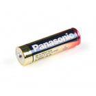
These are your standard 1.5V AA alkaline batteries from Panasonic.
Note: For users interested in using a rechargeable battery, you could also use a NiMH instead of Alkaline.
PRT-00335
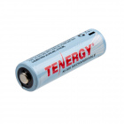
2500mAh 1.2V Nickel Metal Hydride rechargeable 'AA' batteries. [NiMH technology](http://en.wikipedia.org/wiki/Nickel_metal_hy…
Retired
TOL-14457
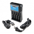
The 4-Bay T4s Intelligent Universal Charger from Tenergy is an automatic smart charger compatible with almost all types of re…
Note: Click below for a wishlist of the minimum parts for Example 3.
An alternative to the Artemis is the ESP32. You will need to ESP32 boards and batteries. Luckily we have the MyoWare 2.0 Muscle Sensor Wireless Kit that provides all that you need!
KIT-25332
The MyoWare® 2.0 Muscle Sensor Wireless Kit is an Arduino-compatible, all-in-one electromyography (EMG) sensor kit.
Retired
Accessories
Depending on your setup, you may need the following accessories to add an extension between the hardware and muscle group.
CAB-12970
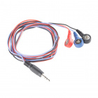
This is your simple three conductor sensor cable with electrode pad leads. These cables are 24" long and feature a 3.5mm audi…
DEV-18386
The MyoWare 2.0 Cable Shield allows you to test and use the MyoWare 2.0 Muscle Sensor without actually attaching the board to…
CAB-19244
The MyoWare® 2.0 Reference Cable is meant as an extension for the MyoWare 2.0 Muscle Sensor's reference pin.
Tools
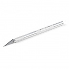
To easily disconnect the boards, we recommend using a flathead screwdriver. The following screwdriver can be used to remove the stack of boards from each other. Depending on the Arduino that you choose, we recommend getting a hobby knife, solder, and soldering iron when changing the jumper pad for the logic levels.
TOL-09163
This is your basic tube of unleaded (Pb-free) solder with a no clean, water soluble resin core. 0.031" gauge and 15 grams
TOL-09507
This is a very simple fixed temp, quick heating, 30W 110/120 VAC soldering iron. We really enjoy using the more expensive iro…
TOL-09146
This is just your basic reversible screwdriver - pocket sized! Both flat and phillips heads available. Comes with pin clip an…
TOL-09200
It's like an Xacto knife, only better. We use these extensively when working with PCBs. These small knives work well for cutt…
You Will Also Need
You will also need the following.
- Alcohol Swab (Isopropyl alcohol and a cotton ball)
- USB isolator circuit (optional)
Suggested Reading
If you aren’t familiar with the following concepts, we recommend checking out these tutorials before continuing. Depending on the Arduino development board that you are using, you may need to install drivers. The RedBoards use a different USB-to-serial converter compared to the Arduino Uno. Both the Arduino Uno and the RedBoard Plus use 5V for the logic levels.
Logic Levels
Learn the difference between 3.3V and 5V devices and logic levels.
RedBoard Plus Hookup Guide
This tutorial covers the basic functionality of the RedBoard Plus. This tutorial also covers how to get started blinking an LED and using the Qwiic system.
For users interested in using a Bluetooth® connection to wirelessly transmit the sensor data, we recommend getting the RedBoard Artemis and installing the board definitions. Note that the RedBoard Artemis uses 3.3V for the logic levels.
Installing Board Definitions in the Arduino IDE
How do I install a custom Arduino board/core? It's easy! This tutorial will go over how to install an Arduino board definition using the Arduino Board Manager. We will also go over manually installing third-party cores, such as the board definitions required for many of the SparkFun development boards.
