MyoWare Muscle Sensor Kit
 .Brent.
 Introduction
As announced previously, Advancer Technologies started a Kickstarter campaign to produce an updated version of their Muscle Sensor v3 board.
MyoWare Muscle Sensor
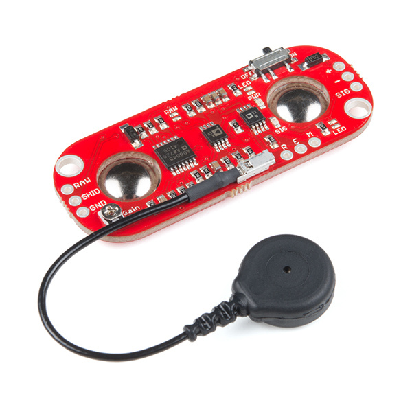
SEN-13723The MyoWare™ Muscle Sensor (AT-04-001) is the latest electromyography (EMG) sensor from Advancer Technologies. Here is an overview of the MyoWare product line and how to use it.
Required Materials
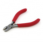
To solder the header pins to the MyoWare shields, you'll need to do some soldering. Soldering tools (including an iron and solder) are a must for any electronics workbench. Diagonal cutters may be used to work with the headers.


Suggested Reading
Before getting started, you may find the following links useful:
How to Solder: Through-Hole Soldering
MyoWare Muscle Sensor
A new version means new features. Here is a breakdown of the new features added to the MyoWare Muscle Sensor Board:
Single-supply — MyoWare won't need ± voltage power supplies! Unlike the previous sensor, it can now be plugged directly into 3.3V - 5V development boards.
Embedded Electrode Connectors — Electrodes now snap directly to MyoWare, getting rid of those pesky cables and making the MyoWare wearable!
RAW EMG Output — A popular request from grad students, the MyoWare now has a secondary output of the RAW EMG waveform.
Polarity Protected Power Pins — The #1 customer request was to add some protection so the sensor chips don't burn out when the power is accidentally connected backwards.
ON/OFF Switch — Speaking of burning out the board, Advancer Technologies also added an on-board power switch so you can test your power connections more easily. It's also handy for saving power.
LED Indicators — Advancer Technologies added two on-board LEDs one to let you know when the MyoWare's power is on and the other will brighten when your muscle flexes.
For more information, please have a look at the official MyoWare Muscle Sensor datasheet.
What is electromyography (EMG)?
An EMG is used to record (graph) the electrical activity (electro) of muscles (myo).
Embedded Electrode Connectors
The embedded electrode connectors allow you to stick the board right to the target muscle and avoid the hassle of wires.
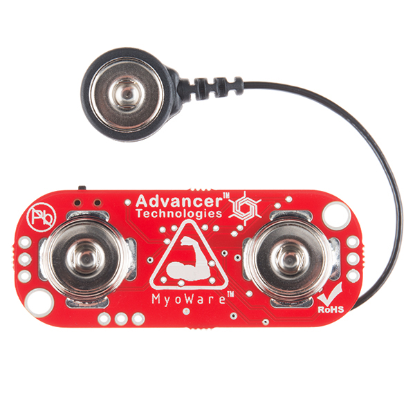
The embedded snap connectors mate well with our Biomedical Sensor Pad (10 pack).
Cable Shield
There may still be cases where you want to mount the sensor pads away from the other hardware. For these cases, we sell the MyoWare Cable Shield.
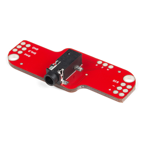
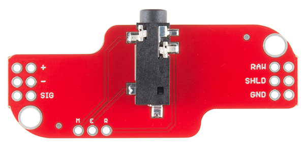
MyoWare Cable Shield
DEV-14109The cable shield provides a jack where you can attach the three electrode cable shown here.
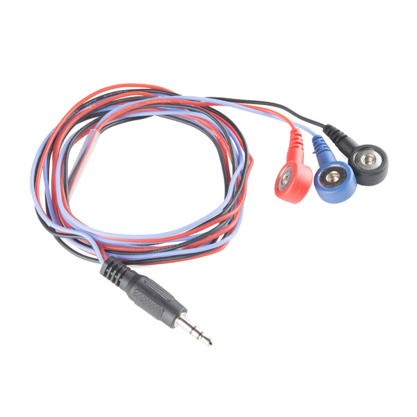
Instead of attaching the sensor pads directly on the MyoWare Muscle Sensor, they can be attached to the shield's 3.5mm TRS jack connector. Both sets of contacts will be connected together, so make sure to only use one pad for each reference [R], end [E], and middle [M] pin.
| Pinout Relative to the Bottom View | v10 [DEV-13687] | v11 [DEV-14109] |
|---|---|---|
| Reference [R] | Blue | Black |
| End [E] | Red | Blue |
| Middle [M] | Black | Red |

Power Shield
The MyoWare Power Shield is designed to take two coin cell batteries such as some standard CR2032s.
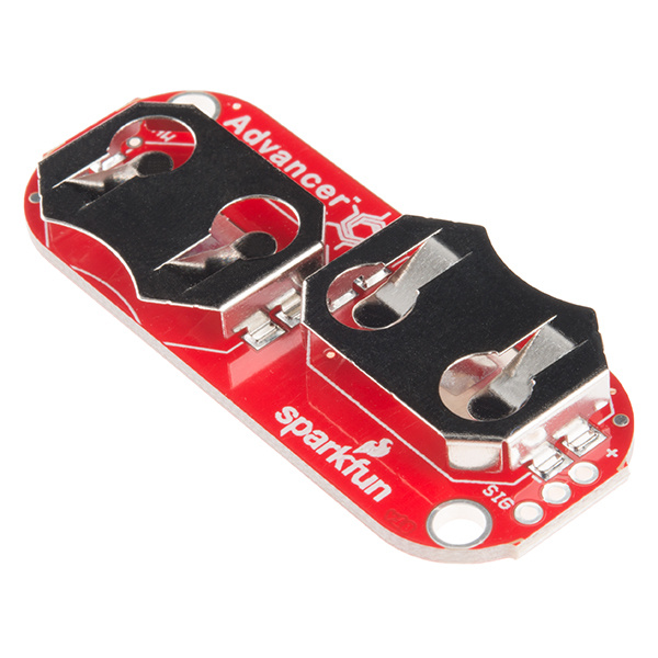
MyoWare Power Shield
DEV-13684They are connected in parallel for extended capacity at a nominal 3.0V. One thing to note is that due to the size of the batteries, the remote cable header can't be passed through. If you need access to these connections, this Power Shield must be stacked above the board(s) that need access.
Battery power allows for a cleaner signal and also eliminates the possibility of creating a dangerous current path to the power grid.
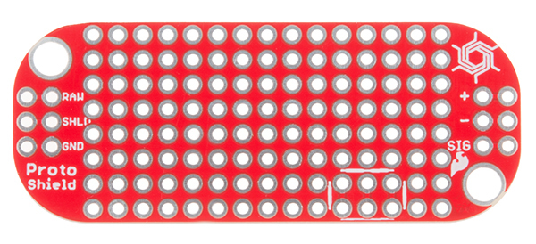
Proto Shield
The MyoWare Proto Shield passes all signals to a bit of protoboard. Use this area to solder on whatever custom circuitry you can come up with.
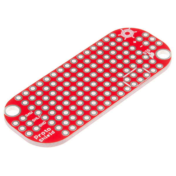
MyoWare Proto Shield
BOB-13709The Cable Shield and the Proto Shield have two rows of 3-pin plated through holes on each end. 'Standard' 0.1" headers to be used to stack them with other boards. Using a combination of male and female headers, this can reduce the profile of the stacked boards.
LED Shield
For those users looking for a large display of the signal level, we offer the the MyoWare LED Shield.
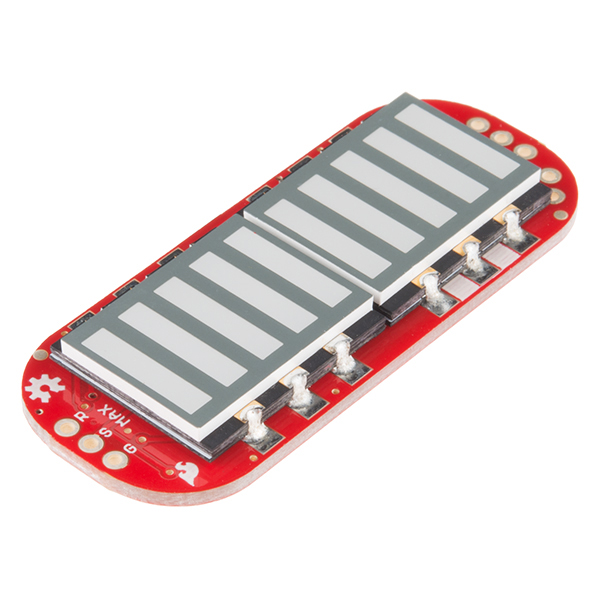
MyoWare LED Shield
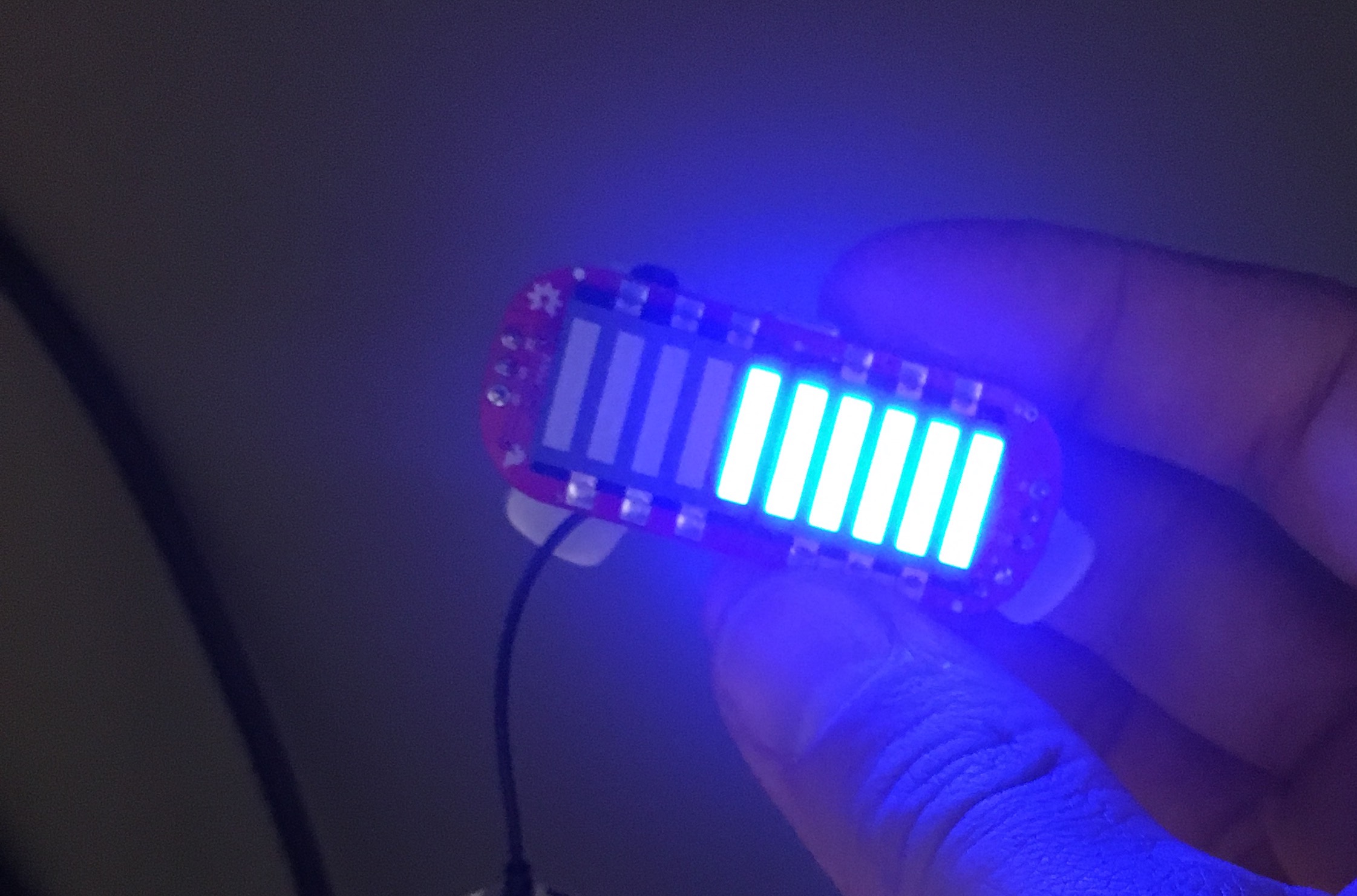
DEV-13688The LED shield provides a large 10-segment bar graph corresponding to the level of the muscle signal measured. This shield is likely to be the top board in a stack. Solder on some 1x3 male headers, and plug it into the sensor board. The power is supplied on the LED shield, but controlled by the power switch on the sensor. Once the stack is assembled, snap on some electrodes, and stick the sensor on the target muscle.

The more muscle activation measured, the higher up the board the lit LEDs will go. In the image above, the two segments near the 'MIN' label are lit, and, if the voltage measured were to increase, the segments to the left would begin to light until the last one labeled 'MAX' is reached. The LEDs are bright enough to be seen in full light, but really glow nice in low light.
Putting it All Together
As mentioned above, there are two ways to attach the sensor pads to a user. They can be attached directly to the sensor board, or to the the end of a cable via the MyoWare Cable Shield.
In the image below, the left most electrode connection should be connected to the end of a muscle group being measured. Again, the cable color codes can vary depending on the manufacture. Relative to the current MyoWare Shield and the electrode cable that is sold in SparkFun's catalog, this is equivalent to using the blue insulated conductor connected to the pin labeled E. The mid muscle electrode on the right breaks out on the red snap on the cable connected to the pin labeled M. The reference electrode has continuity with the black snap connected to the pin labeled R.
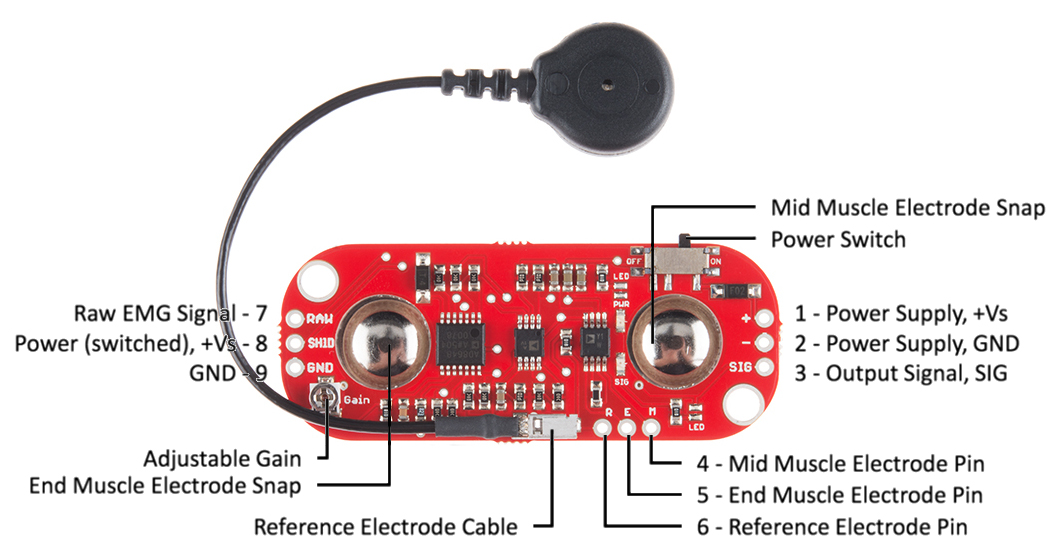
As shown in the image above, there are three rows of three 0.1" spaced plated through holes. On the right is the power supply +Vs, & ground, along with the processed output signal (holes 1, 2, & 3).
Along the long edge near the mid muscle electrode snap are the thru-holes for remote electrode connection (holes 4, 5, & 6).
On the opposite end are three 'outputs'. Hole 7 is the raw, unprocessed EMG signal. Hole 8 is the switched power. Power goes into the board via hole 1, is switched, and comes back out hole 8 ( if you believe in passive sign convention (PSC) ). Hole 9 is the ground reference for the switched power.
The shields come with assorted support for these pins. Some shields such as the Power Shield don't support the remote connections. If you need access to these pins the boards that use or can pass them through must go lower in the stack. Both the Cable Shield and the Proto Shield have this connection capability.
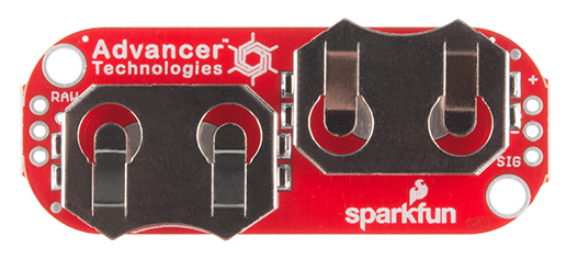
MyoWare Power Shield (top view)
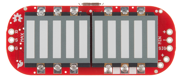
MyoWare LED Shield (top view)
MyoWare Cable Shield (bottom view)
MyoWare Proto Shield (top view)
Take note of the second row of holes on the Cable and Proto shields. This allows for stacking multiple shields using standard 0.1" headers or the stackable variety.


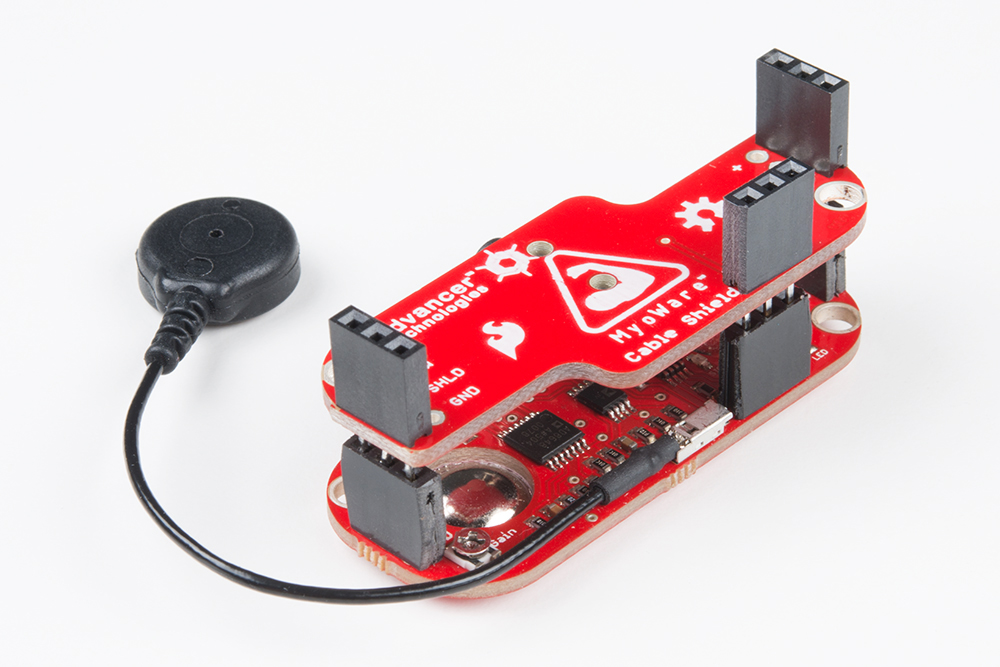
Option 1
The headers listed provides the user with a few options to stack the shields together. We found it easier to have the MyoWare sensor and shields populated with female headers. If using the stackable headers supplied with the kit, it is likely that you will want to flush cut the long leads from the bottom using diagonal cutters. Below is an example of the cable shield stacked on the MyoWare sensor.

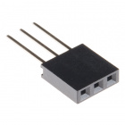
3-Pin Stackable Header
Option 2
It's also possible to have a setup where you might want use male header pins in the stack. If using the parts provided in the kit, these male headers will likely be populated on the bottom stack. The bottom board should in most cases have male headers populated on the outer bottom rows to mate with the boards that will be stacked on top. The board to be stacked on top should have female headers facing the male header pins.
Resources and Going Further
Thanks for reading. For more information on the MyoWare product line, please visit the following links.
- Official MyoWare™ datasheet
- Sensor Pad Datasheet
- Official Advancer Technologies Website
- Advancer Technologies GitHub Repository
- MyoWare™ GitHub Repository
- Arduino Example Code
For more cool projects and ideas, check out the following SparkFun tutorials.