MAX30105 Particle and Pulse Ox Sensor Hookup Guide
 Nate
Nate Introduction
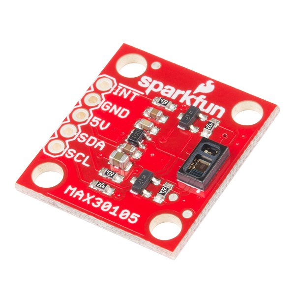
The SparkFun MAX30105 Particle Sensor is a flexible and powerful sensor enabling sensing of distance, heart rate, particle detection, even the blinking of an eye. This tutorial will get you up and running to get the raw data from the sensor.
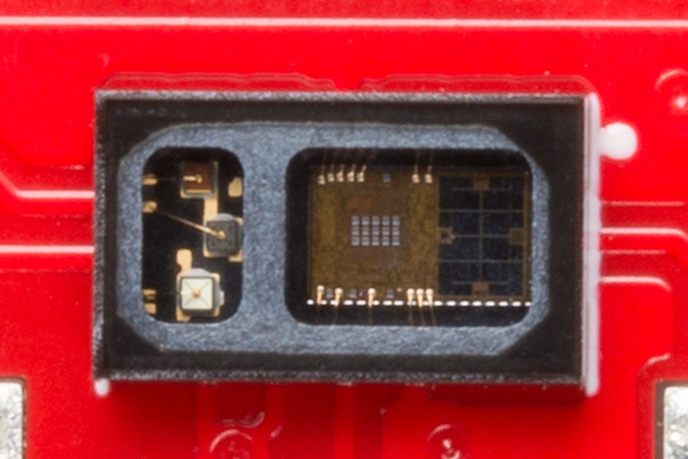
Behind the window on the left, the MAX30105 has three LEDs. On the right is a very sensitive photon detector. The idea is that you obstruct the different LEDs, detecting what light shines back at the detector, and, based on the signature, you can tell the presence of different types of particles or materials (such as oxygenated blood or smoke from a fire).
Suggested Materials
You'll need a handful of extra parts to get the MAX30105 breakout up-and-running. Below are the components used in this tutorial, if you want to follow along.
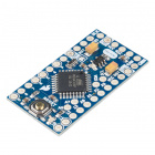
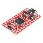
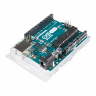
A microcontroller that supports I2C is required to communicate with the MAX30105 and relay the data to the user. The SparkFun RedBoard or Arduino Uno are popular options for this role, but just about any microcontroller development board should work. (The firmware examples use an Arduino library, if that serves as any extra motivation to use an Arduino.)

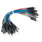
Four or five jumper wires and a breadboard help interface the sensor to your Arduino. To insert the breakout into the breadboard, you'll need to solder headers or cut jumper wires to the pins. (Don't forget a soldering iron and solder!)


Suggested Reading
The MAX30105 is designed for a handful of uses including Pulse Oximetry. If you're unfamiliar with optical pulse detection there are some very good app notes from TI and NXP that have great starter information.
The MAX30105 communicates over I2C. We’ve got a great library to make it easy to use. And, we’re going to be using a breadboard to connect the breakout board to the RedBoard. If any of these subjects sound foreign to you, consider browsing through that tutorial before continuing.
How to Solder: Through-Hole Soldering
Installing an Arduino Library
How to Use a Breadboard
I2C
MAX30105 Breakout Overview
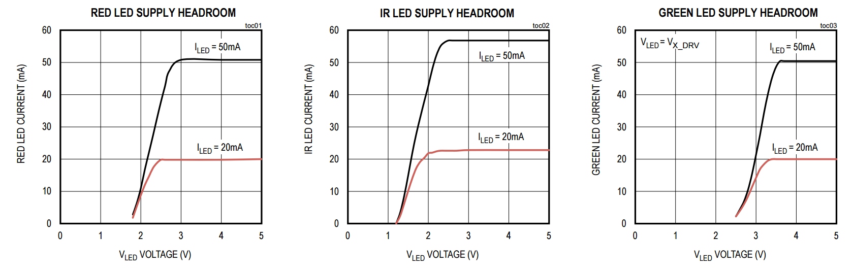
The MAX30105 has three on-board LEDs (seen on the left). Maxim recommends these LEDs be powered from 5V, but we've found the LEDs work fine at 3.3V. The red and IR LEDs are guaranteed to work at 3.3V, but the green LED may need 3.5V. It's best to try out your board at 3.3V and see if the green LED illuminates.
The IC itself runs at 1.8V, so we’ve included the interface logic to allow you to hook the MAX30105 Breakout Board to any board that has 5V, 3.3V, even 1.8V level I/O.
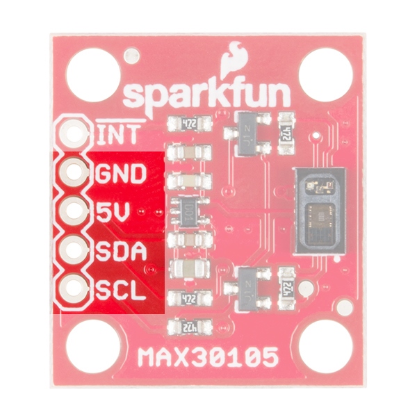
| Pin Label | Input/Output | Description |
|---|---|---|
| INT | Output | Interrupt, active low |
| GND | Supply Input | Ground (0V) supply |
| 5V | Supply Input | Power supply |
| SDA | Bi-directional | I2C bus clock line |
| SCL | Input | I2C bus clock line |
The GND/5V/SDA/SCL pin-out is the standard I2C connection on most of our products. This allows you to easily connect I2C boards to many of our platforms.
There are two jumpers on the back of the PCB:
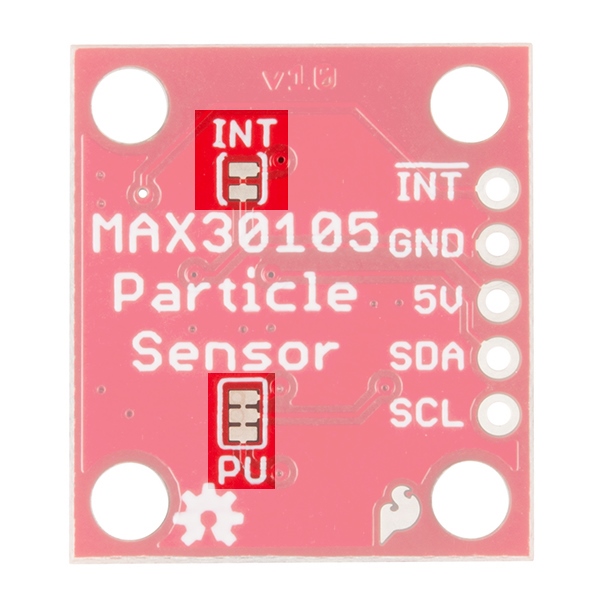
The PU jumper is used on many I2C boards to allow the user to disconnect the 4.7k Ohm pull-up (PU) resistors from the SDA and SCL lines. By default, this jumper is closed meaning there are 4.7k pull-up resistors on SDA and SCL. If this is the only device on the I2C bus, then this jumper should be left closed. If there are multiple I2C devices or breakout boards on the bus with pull-up resistors, then the traces in this jumper should be cut to remove the 4.7k Ohm resistors from the bus. If needed, the jumper can be re-soldered to close it again in the future.
The INT jumper is used to control the pull-up resistor on the interrupt pin. The INT jumper is closed by default, which means a 4.7k resistor is pulling up the interrupt pin. The INT pin on the MAX30105 is an open drain pin. If there is only one board on your I2C bus, this jumper should be left closed. If there are multiple boards on the I2C bus sharing a single interrupt pin, this jumper can be cut to disconnect the pull up resistor.
Hardware Hookup
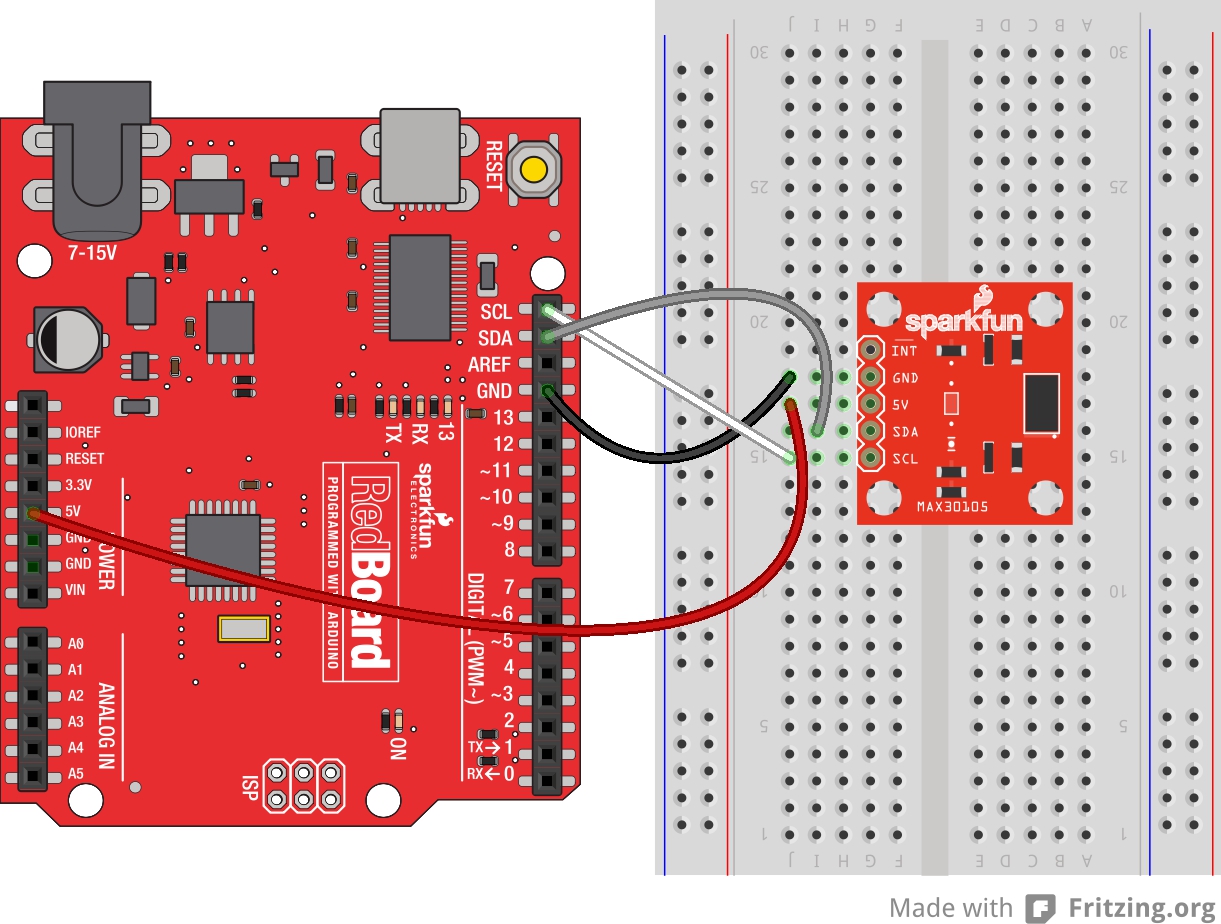
Because this sensor can be used in a multitude of ways, consider how you're going to use the MAX30105 before soldering. If you plan to use the sensor for pulse oximetry, we recommend soldering short wires to the board to enable some movement when the sensor is attached to a finger. If you're more interested in static sensing like particle or air monitoring, consider soldering male headers to the board.
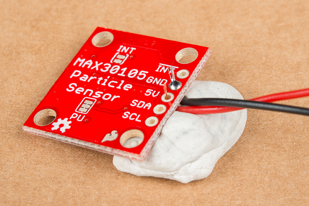
Here's an example of using jumper wires to make a robust connection to the MAX30105 board.
These jumper wires contain stranded wire, which make them more flexible and less prone to breaking from repeated movement.
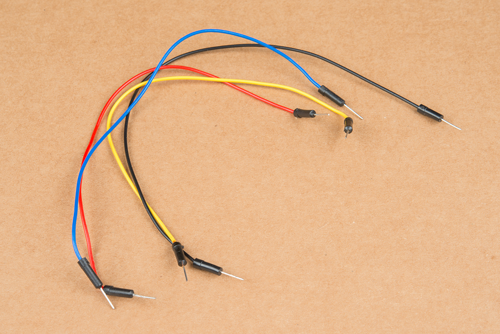
Pick four different color wires, and cut them to your desired length. We use red, black, yellow and blue to make things easy to identify.
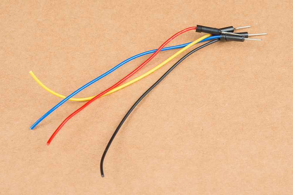
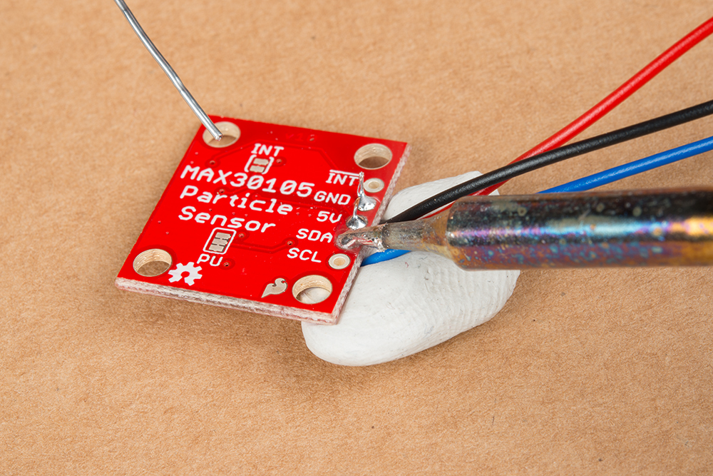
Strip the ends of the wire, and solder them into their various spots. A connection to the INT pin is optional and not needed for the Arduino examples below.
Getting small gauge wires to stay in place can be tough. I like to use sticky tack to hold everything in place while I solder.
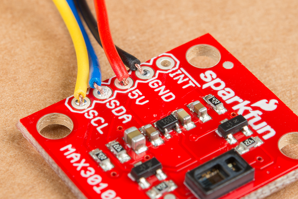
You can pick any colors you want, but using different colors for each pin will make it easier to distinguish between connections.
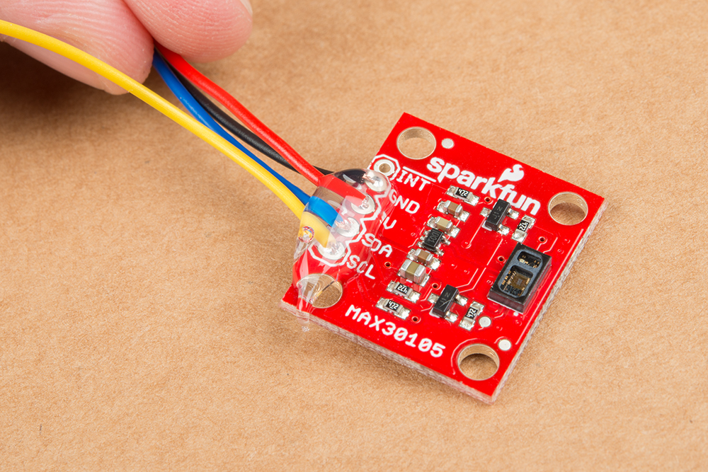
Stranded wire is better at flexing than solid core wire. However, without stress relief, even these stranded wires may break due to lots of flexing.
Adding a bit of hot-glue where the wires meet the PCB will make the board even more robust and resistant to damage when you start "speaking" with your hands.
Using the SparkFun MAX30105 Arduino Library
Let’s get right to it! We've written an Arduino library for the MAX30105 and MAX30102 (it should work with the MAX30101 as well), which takes care of all of the I2C communication, bit-shifting, register-writing, and sample-reading. The library supports the MAX30102 (Red and IR LEDs only) and the MAX30105 (Red, IR, and Green LEDs).
The easiest way to install the library is through the Arduino Library manager.
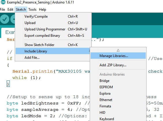
Type MAX30105 into the Search box and select the SparkFun Library.
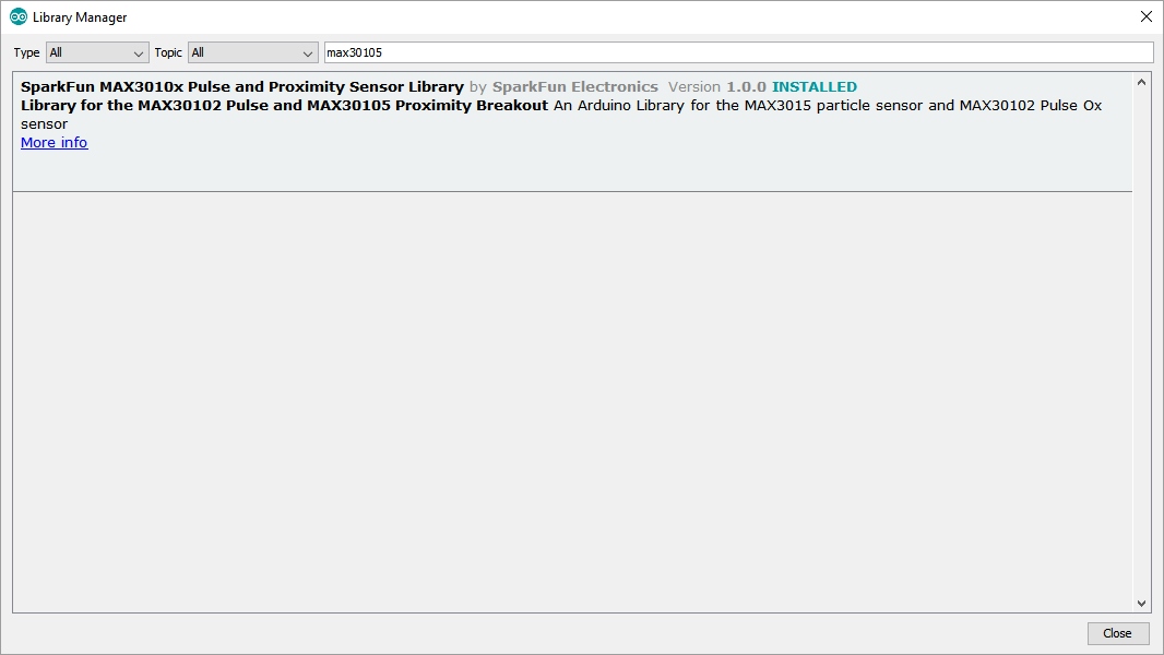
Click on the SparkFun library to highlight it, then click on the Install button.
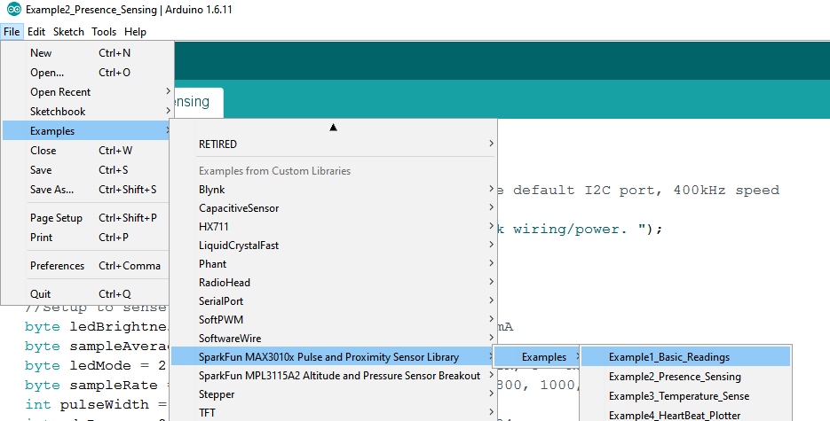
Once you’ve downloaded the library, you should see the Example sketches by navigating to
File > Examples > SparkFun MAX3010x Pulse and Proximity Sensor Library > Examples
While you're there, go ahead and open Example1 Basic Readings.
If you'd rather grab the most recent version of the library from our SparkFun MAX3010x Sensor GitHub repository, you can do that too!
Then follow along with our How to Install an Arduino Library tutorial for help installing the library. If you download the library's ZIP file, you can use Arduino's "Add ZIP Library..." feature to install the source and example files with just a couple clicks.
Example 1 - Reading Red/IR/Green
Once you've got the library installed, open the Example1 Basic Readings sketch. You can find it under
File > Examples > SparkFun MAX3010x Pulse and Proximity Sensor Library > Examples
Then load it onto your RedBoard or Uno. Open your favorite Serial Terminal to see the printed values.
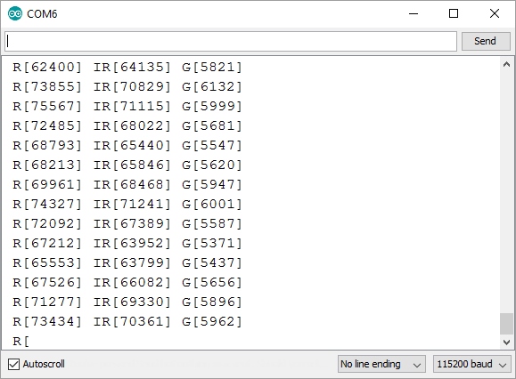
This example outputs the raw values read by the sensor. With the sensor pointing up, use your hand to hover over the sensor. You should see a change in values as your hand reflects different amounts of light. Note that the IR readings will probably change before the Red and Green readings. IR is better at sensing distance changes.
Completely cover the sensor with your finger. Note the very large readings. This is one of the features that sets the MAX30105 from other reflectance sensors. The IC is capable of reading up to 18-bits or values up to 262,144. An extremely small change in light can be detected!
The MAX30105 is easy to use! Calling particleSensor.getGreen() will take a reading and return the reflected amount of green light.
Example 2 - Presence Sensing
Open the Example2 Presence Sensing sketch, and load it onto your RedBoard or Uno.
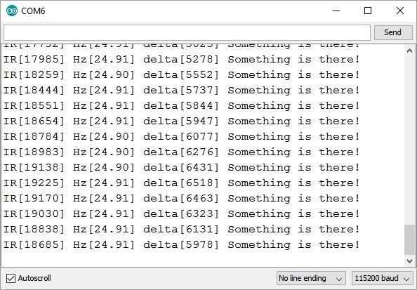
This example takes a handful of readings during setup and averages them together. It uses this average as a baseline. If the sensor detects a significant change from the average, then “Something is there!” is printed. This is useful when you need to detect if a ball drops through a channel or other photo-gate situations. It's also handy for testing the range at which the sensor can detect something.
language:c
//Setup to sense up to 18 inches, max LED brightness
byte ledBrightness = 0xFF; //Options: 0=Off to 255=50mA
byte sampleAverage = 4; //Options: 1, 2, 4, 8, 16, 32
byte ledMode = 2; //Options: 1 = Red only, 2 = Red + IR, 3 = Red + IR + Green
byte sampleRate = 400; //Options: 50, 100, 200, 400, 800, 1000, 1600, 3200
int pulseWidth = 411; //Options: 69, 118, 215, 411
int adcRange = 2048; //Options: 2048, 4096, 8192, 16384

particleSensor.setup(ledBrightness, sampleAverage, ledMode, sampleRate, pulseWidth, adcRange); //Configure sensor with these settings
During setup this code initializes the sensor. There are many different options and configurations for the MAX30105. You can define as many or as few as you'd like. You can also skip them all:
language:c
particleSensor.setup(); //Configure sensor with default settings
The sensor will be configured with the default settings. The default settings work for most applications.
Example 3 - Temperature Sensor
Open the Example3 Temperature Sense sketch, and load it onto your RedBoard or Uno.
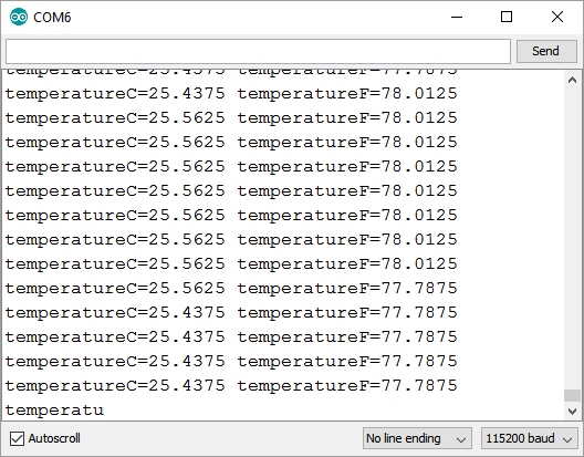
This example outputs readings from the on-board temperature sensor in both Celsius and Fahrenheit. The temp sensor is accurate to +/-1 C but has an astonishing precision of 0.0625 C.
The temperature is used internally by the sensor to calibrate its samples but can be useful if you need a sensitive and fast responding temp sensor.
Example 4 - Heart Beat Plotting
This is where the fun really begins! Hemoglobin reflects IR light really well, and the MAX3015 is capable of detecting such small changes in IR reflectance that it can detect blood flowing through your finger at different rates. Let's graph it! Open the Example4 HeartBeat Plotter sketch, and load it on your Redboard or Uno.
For this demo, you'll need a rubber band small enough to go through the mounting holes on the breakout.
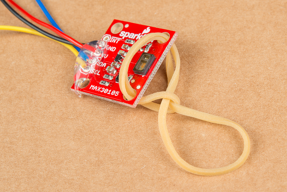
Loop the band back onto itself, and pull gently. You want a little bit of pressure holding your finger against the sensor. If the end of your finger turns pale, you've tightened too much!
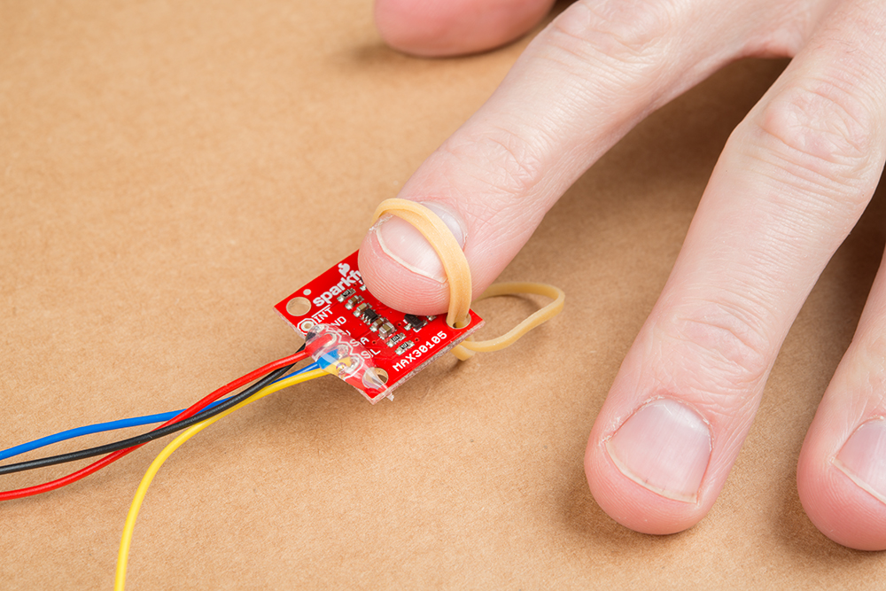
Humans are bad at applying consistent pressure to a thing. Without a rubber band the pressure varies enough to cause the blood in your finger to flow differently which causes the sensor readings to go wonky. It is best to attach the sensor to your finger using a rubber band or other tightening device.

Instructions:
- Load code onto Redboard
- Attach sensor to your finger with a rubber band
- Open Tools->Serial Plotter
- Make sure the drop down is set to 115200 baud
- Checkout the blips!
- Feel the pulse on your neck and watch it mimic the blips
Now that we have seen the blips, Example 5 will try to calculate the time between blips and show us beats per minute (BPM).
Example 5 - HeartRate
Open the Example5 HeartRate sketch, and load it on your Redboard or Uno.
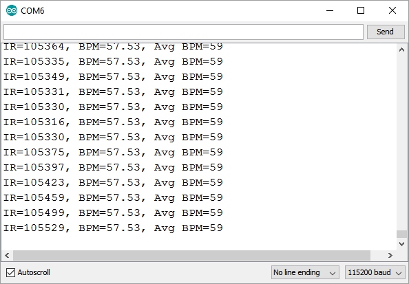
This example runs a filter called the PBA or Penpheral Beat Amplitude algorithm on the IR data. This algorithm is able to pull out the blips from all the noise and calculate the time between blips to get a heart rate. The output is your instantaneous heart rate and your average heart rate (BPM).
As one might expect the human body isn't as precise as a metronome. The time between pulses can vary quite a bit so this sketch takes a running average of 4 readings to try to smooth out the variance.
Trouble? Try moving the sensor to a different finger. The rubber rand should be snug but not tight. The algorithm takes a few seconds to determine the peaks and troughs, so each time you move the sensor, wait a few seconds for the readings to make sense.
Advanced Functions
The MAX30105 is highly configurable, and there are a large number of functions exposed in the library to the user. Checkout the MAX30105.h file for all the functions, but here are the major ones. Read the MAX30105 datasheet for more information.
The library supports the following functions:
.begin(wirePort, i2cSpeed)- If you have a platform with multiple I2C ports, pass the port object when you call begin. You can increase the I2C speed to 400kHz by including I2C_SPEED_FAST when you call.begin()as well..setup()- Initializes the sensor with various settings. See the Example 2 for a good explanation of the options..getRed()- Returns the immediate red value.getIR()- Returns the immediate IR value.getGreen()- Returns the immediate Green value.available()- Returns how many new samples are available.readTemperature()- Returns the temperature of the IC in C.readTemperatureF()- Returns the temperature of the IC in F.softReset()- Resets everything including data and configuration.shutDown()- Powers down the IC but retains all configuration.wakeUp()- Opposite of shutDown.setLEDMode(mode)- Configure the sensor to use 1 (Red only), 2 (Red + IR), or 3 (Red + IR + Green) LEDs.setADCRange(adcRange)- Set ADC to be at 2048, 4096, 8192, or 16384.setSampleRate(sampleRate)- Configure the sample rate: 50, 100, 200, 400, 800, 1000, 1600, 3200
Interrupts
.getINT1()- Returns the main interrupt group.getINT2()- Returns the temp ready interrupt
Enable/disable individual interrupts. See page 13 and 14 of the datasheet for an explanation of each interrupt:
.enableAFULL().disableAFULL().enableDATARDY().disableDATARDY().enableALCOVF().disableALCOVF().enablePROXINT().disablePROXINT().enableDIETEMPRDY().disableDIETEMPRDY()
FIFO
The MAX30105 has a 32 byte FIFO. This allows us do other things on our microcontroller while the sensor is taking measurements. See Example 6 for an explanation of how to poll the FIFO.
.check()- Call regularly to pull data in from sensor.nextSample()- Advances the FIFO.getFIFORed()- Returns the FIFO sample pointed to by tail.getFIFOIR()- Returns the FIFO sample pointed to by tail.getFIFOGreen()- Returns the FIFO sample pointed to by tail
Resources and Going Further
For more on the MAX30105 Particle Sensor Breakout Board the Maxim MAX3010x, check out the links below:
- MAX30105 Breakout Board GitHub Repository -- Home base for the sensor's latest design files
- MAX30105 Breakout Board Schematic (PDF)
- MAX30105 Breakout Board Eagle Files (ZIP)
- MAX30105 Datasheet (PDF)
- SparkFun MAX3010x Sensor Library GitHub Repository -- Source and example files for the Arduino library used in this tutorial.
- SFE Product Showcase
How Can You Help?
The MAX30105 is a very powerful sensor but we’ve only scratched the surface of what it's capable of. If you are an algorithms guru and have a better method for calculating heart rate, or SPO2, or particle detection we would love to hear from you! Please send us a link to your repo, and we’ll include it here.
For more sensor action, check out these other great SparkFun tutorials.