How to Use a Breadboard
 M-Short,
  Joel_E_B
 Introduction
Breadboards are one of the most fundamental pieces when learning how to build circuits. In this tutorial, you will learn a little bit about what breadboards are, why they are called breadboards, and how to use one. Once you are done you should have a basic understanding of how breadboards work and be able to build a basic circuit on a breadboard.
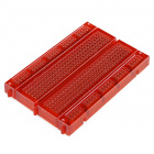
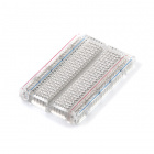
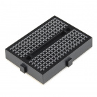
Looking for the Breaboard that's right for you?
We've got you covered!


Suggested Reading
Here are some tutorials and concepts you may want to explore before learning about breadboards:
Connector Basics
What is a Circuit?
Voltage, Current, Resistance, and Ohm's Law
Working with Wire
How to Read a Schematic
How to Use a Multimeter

Turn Your Breadboard Into Real Projects
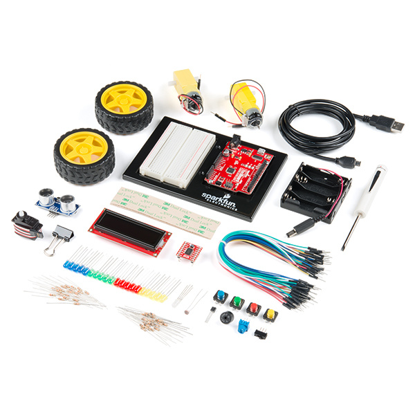
The SparkFun Inventor's Kit includes a full set of components and guided experiments designed to help you build circuits with a breadboard—no soldering required.
Build Your First CircuitsHistory
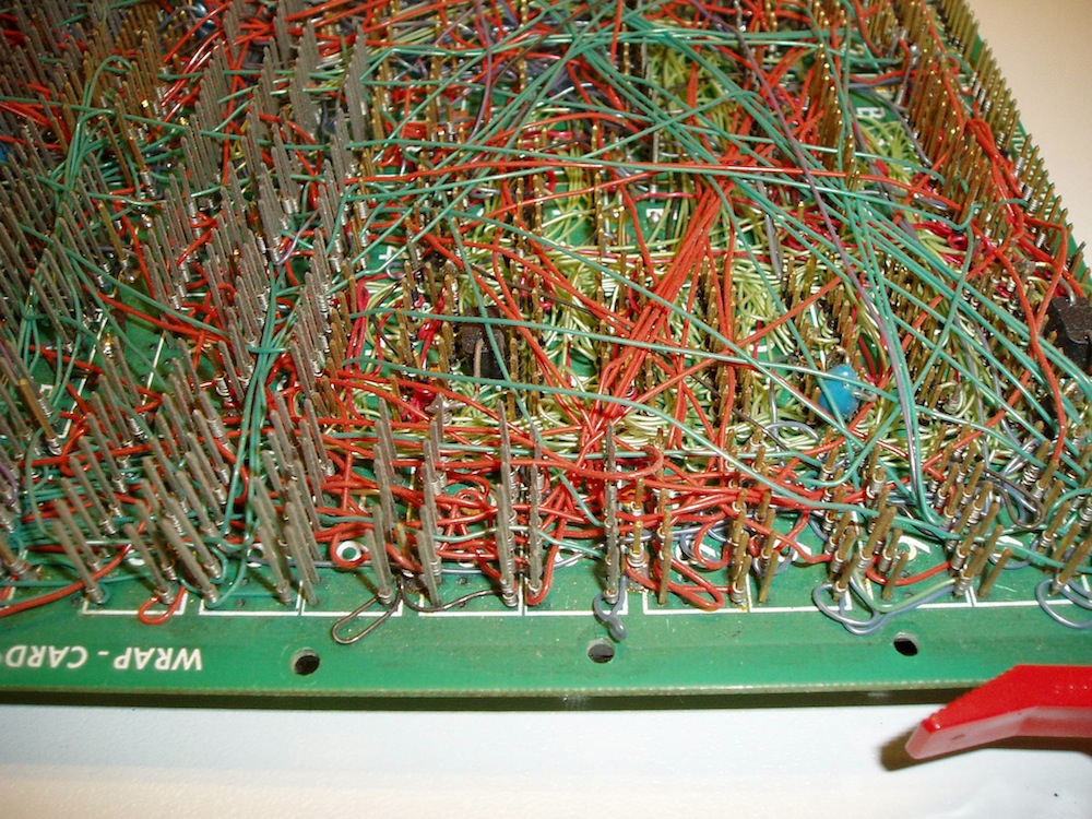
If you wanted to build a circuit prior to the 1960s, chances are you would have used a technique called wire-wrap. Wire wrap is a process that involves wrapping wires around conductive posts attached to a perfboard (a.k.a. a protoboard). As you can see, the process can get rather complex very quickly.Although this method is still used today, there is something that makes prototyping much easier, breadboards!
What’s in a Name?
When you picture a breadboard in your head, you may envision a big piece of wood and a large loaf of freshly baked bread. You wouldn’t be too far off either.
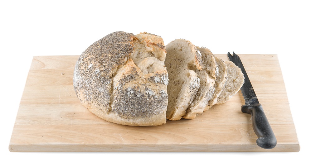
So why do we call this electronic “circuit builder” a breadboard? Many years ago, when electronics were big and bulky, people would grab the nearest breadboard, a few nails or thumbtacks, and start connecting wires onto the board to give themselves a platform on which to build their circuits.

Since then, electronic components have gotten a lot smaller, and we’ve come up with better ways to connect circuits, making people all over the world happy to have their breadboards back. However, we are stuck with the confusing name. Technically, these are still breadboards, but this discussion is going to be on modern, "solderless" breadboards.
Why Use Breadboards?
An electronics breadboard (as opposed to the type on which sandwiches are made) is actually referring to a solderless breadboard. These are great units for making temporary circuits and prototyping, and they require absolutely no soldering.
Prototyping is the process of testing out an idea by creating a preliminary model from which other forms are developed or copied, and it is one of the most common uses for breadboards. If you aren’t sure how a circuit will react under a given set of parameters, it’s best to build a prototype and test it out.
For those new to electronics and circuits, breadboards are often the best place to start. That is the real beauty of breadboards--they can house both the simplest circuit as well as very complex circuits. As you'll see later in this tutorial, if your circuit outgrows its current breadboard, others can be be attached to accommodate circuits of all sizes and complexities.
Another common use of breadboards is testing out new parts, such as Integrated circuits (ICs). When you are trying to figure out how a part works and constantly rewiring things, you don’t want to have to solder your connections each time.
As mentioned, you don’t always want the circuit you build to be permanent. When trying to duplicate a customer’s problem, SparkFun’s Technical Support team will often use breadboards to build, test, and analyze the circuit. They can connect the parts the customer has, and once they’ve gotten the circuit setup and figured out the problem, they can take everything apart and put it aside for the next time they need to do some troubleshooting.
Anatomy of a Breadboard
The best way to explain how a breadboard works is to take it apart and see what’s inside. Using a smaller breadboard it’s easier to see just how they function.
Terminal Strips
Here we have a breadboard where the adhesive backing has been removed. You can see lots of horizontal rows of metal strips on the bottom of the breadboard.
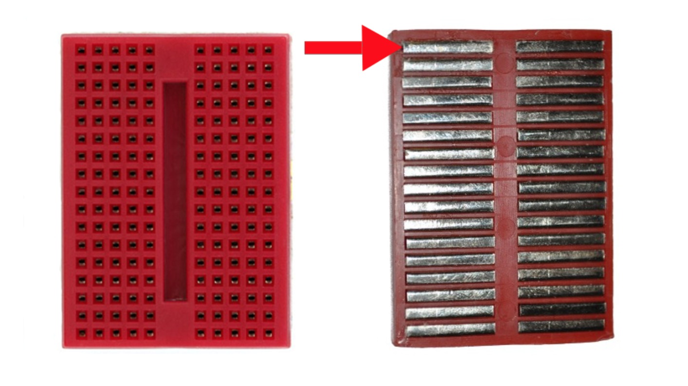
The tops of the metal rows have little clips that hide under the plastic holes. Each metal strip and socket is spaced with a standard pitch of 0.1" (2.54mm). These clips allow you to stick a wire or the leg of a component into the exposed holes on a breadboard, which then hold it in place.
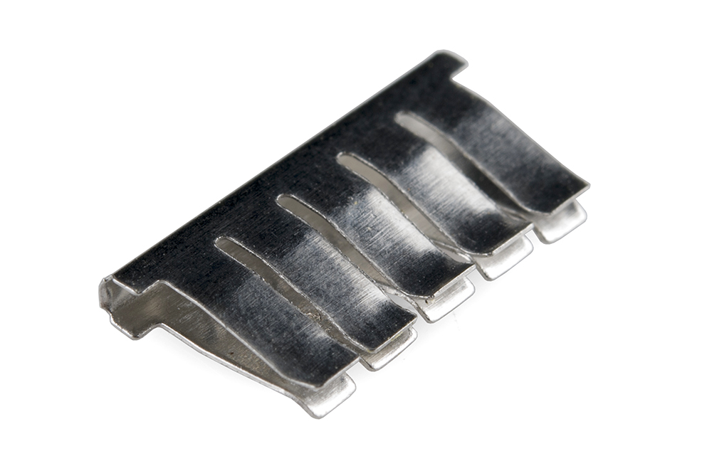
Once inserted that component will be electrically connected to anything else placed in that row. This is because the metal rows are conductive and allow current to flow from any point in that strip.
Notice that there are only five clips on this strip. This is typical on almost all breadboards. Thus, you can only have up to five components connected in one particular section of the breadboard. The row has ten holes, so why can you only connect five components? You’ll also notice that each horizontal row is separated by a ravine, or crevasse, in the middle of the breadboard. This ravine isolates both sides of a given row from one another, and they are not electrically connected. We’ll discuss the purpose of this in just a bit, but, for now, just know that each side of a given row is disconnected from the other, leaving you with five spots for components on either side.
Power Rails
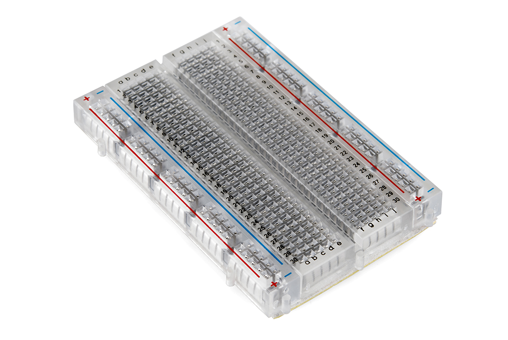
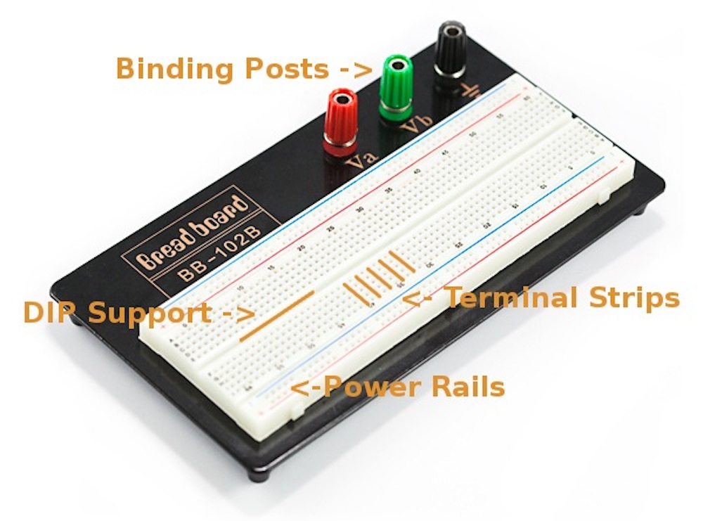
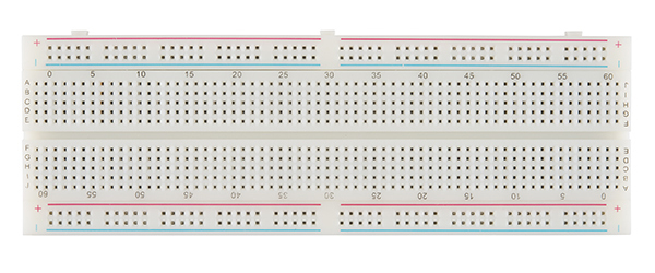
Now that we’ve seen how the connections in a breadboard are made, let’s look at a larger, more typical breadboard. Aside from horizontal rows, breadboards usually have what are called power rails that run vertically along the sides.
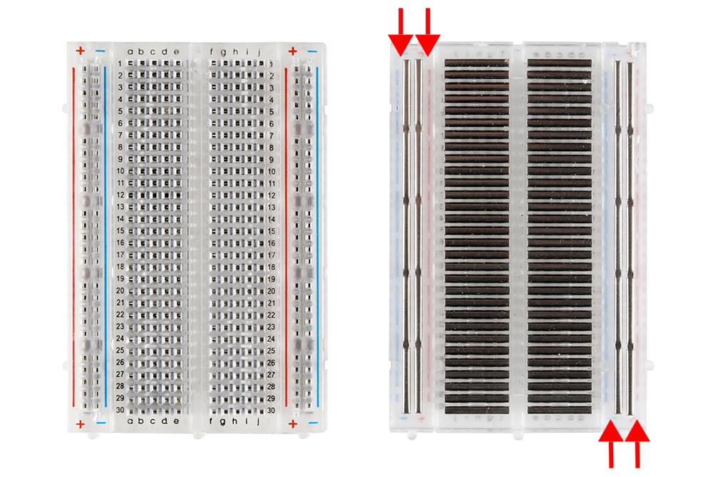
These power rails are metal strips that are identical to the ones that run horizontally, except they are, typically*, all connected. When building a circuit, you tend to need power in lots of different places. The power rails give you lots of easy access to power wherever you need it in your circuit. Usually they will be labeled with a ‘+’ and a ‘-’ and have a red and blue or black stripe, to indicate the positive and negative side.
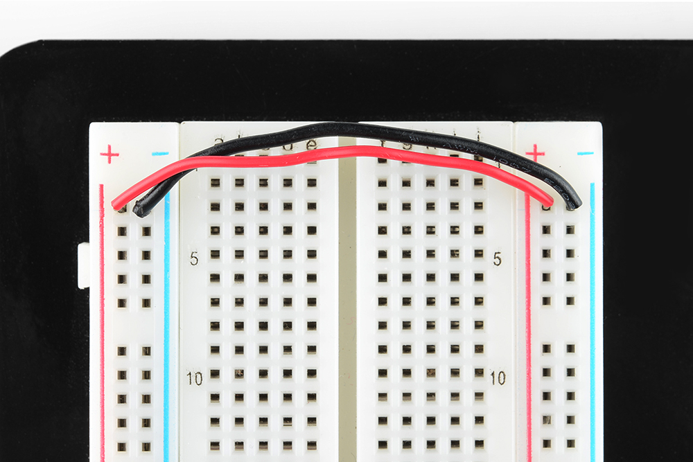
It is important to be aware that the power rails on either side are not connected, so if you want the same power source on both sides, you will need to connect the two sides with some jumper wires. Keep in mind that the markings are there just as a reference. There is no rule that says you have to plug power into the '+' rail and ground into the '-'rail, though it's good practice to keep everything in order.
DIP Support
Earlier we mentioned the ravine that isolates the two sides of a breadboard. This ravine serves a very important purpose. Many integrated circuits, often referred to as ICs or, simply, chips, are manufactured specifically to fit onto breadboards. In order to minimize the amount of space they take up on the breadboard, they come in what is known as a Dual in-line Package, or DIP.
These DIP chips (salsa anyone?) have legs that come out of both sides and fit perfectly over that ravine. Since each leg on the IC is unique, we don’t want both sides to be connected to each other. That is where the separation in the middle of the board comes in handy. Thus, we can connect components to each side of the IC without interfering with the functionality of the leg on the opposite side.

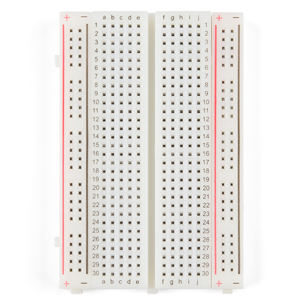
Rows and Columns
You may have noticed that many breadboards have numbers and letters marked on various rows and columns. These don't serve any purpose other than to help guide you when building your circuit. Circuits can get complicated quickly, and all it takes is one misplaced leg of a component to make the entire circuit malfunction or not work at all. If you know the row number of the connection you are trying to make, it makes it much simpler to plug a wire into that number rather than eyeballing it.
These are also helpful when using instruction booklets, such as the one found in the SparkFun Inventor’s Kit. Many books and guides have circuit diagrams for you to follow along while building your circuit. Just remember that the circuit you’re building doesn’t have to be in the exact same location on the breadboard as the one in the book. In fact, it doesn’t even have to look similar. As long as all the electrical connections are being made, you can build your circuit any way you’d like!
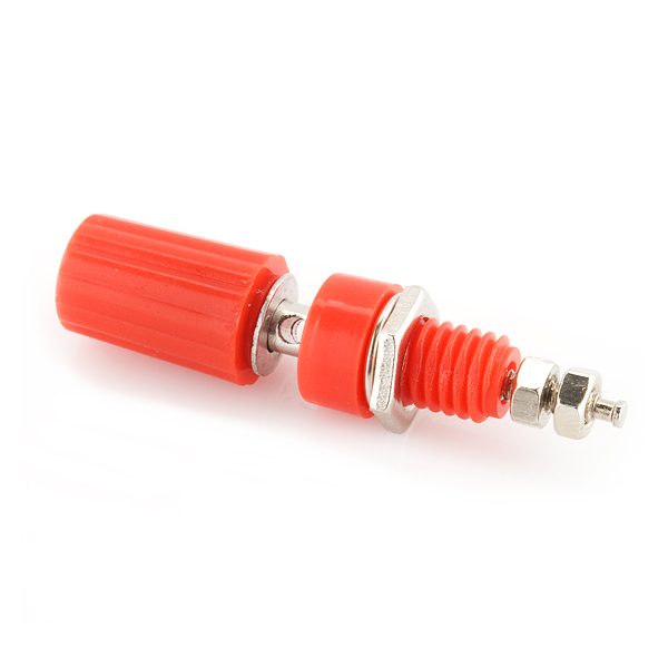
Binding Posts
Some breadboards come on a platform that has binding posts attached to it. These posts allow you to connect all kinds of different power sources to your breadboard. We'll cover these more in the next section.
 |
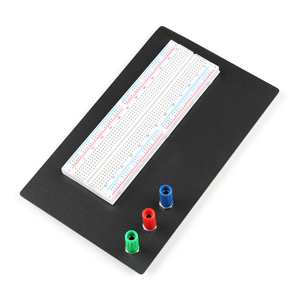 |
| Binding Post for Banana Cables and Wires | Binding Posts on Classic Breadboard |
Other Features
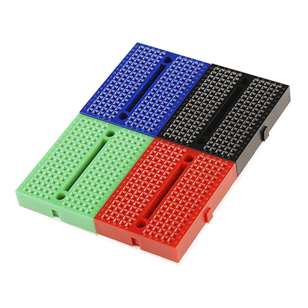
When building your circuit, you are not confined to stay on just one breadboard. Some circuits will require a lot more space. Many breadboards have little nubbins and slots on the sides, and some even have them on the tops and bottoms. These allow you to connect multiple breadboards together to form the ultimate prototyping surface.
Some breadboards also have an adhesive backing that allow you to stick them to many different surfaces. These can come in handy if you want to attach your breadboard to the inside on an enclosure or other project case.
Providing Power to a Breadboard
When it comes to providing power to you breadboard, there are numerous options.
Borrowing from Other Power Sources
If you are working with a development board such as an Arduino, then you can simply pull power from the Arduino’s female headers. The Arduino has multiple power and ground pins that you can connect to the power rails or other rows on a breadboard.
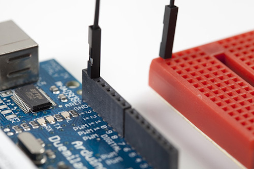
The Arduino usually gets its power from the USB port on a computer or an external power supply such as a battery pack or a wall wart.
Binding Posts
As mentioned in the previous section, some breadboards have binding posts that allow you to connect external power sources.
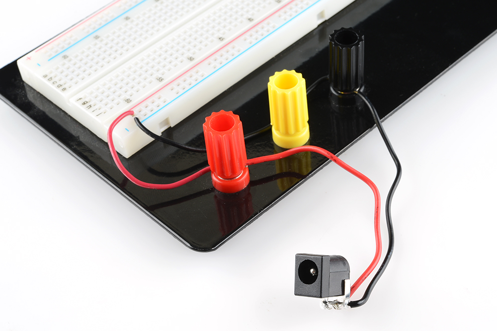
The first step to using the binding posts is to connect them to the breadboard using some jumper wires. Although it would seem that the posts are connected to the breadboard, they are not. If they were, you would be limited to where you could and couldn’t provide power. As we’ve seen, breadboards are meant to be totally customizable, so it would make sense that the binding posts are no different.
With that, we have to connect wires to the posts in order to connect them to the breadboard. To do that, unscrew the post until the hole going through it is exposed. Slide the stripped end of your jumper wire through the hole, and screw the post back down until the wire is firmly connected.
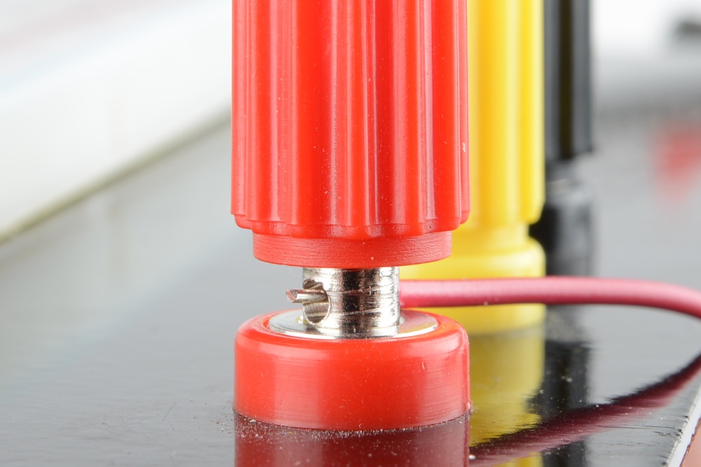
Typically, you only need to connect a power and ground wire from the posts to the breadboard. If you need an alternate power source, you can use the third post.
Now your posts are connected to the the breadboard, but there is still no power. You can use many different methods to connect power to the posts, and, thus, to the breadboard.
Benchtop Power Supplies
Many electronics labs have benchtop power supplies that allow you to provide a wide range of voltage and current to your circuit. Using a banana connector you can provide power from the supply to the binding posts.
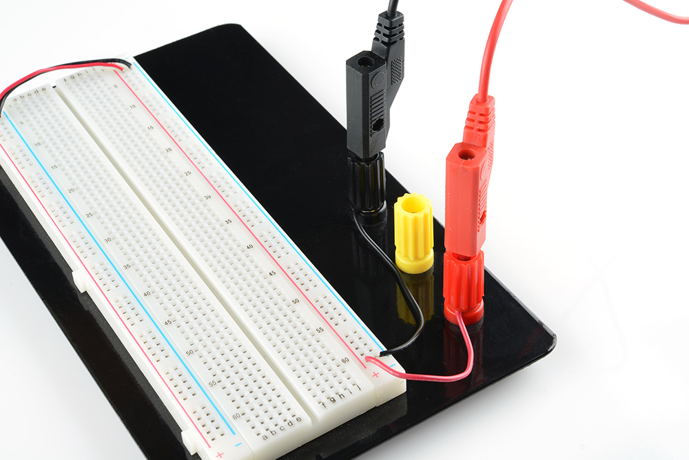
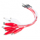
Alternatively, you could use alligator clips, IC hooks, or any other cables with a banana connection to hook your breadboard up to a number of different supplies.
Another method of using the binding posts is to solder a barrel jack to some wires, and then connect them to the binding posts. This is a more advanced technique, and it requires some intermediate soldering skills.
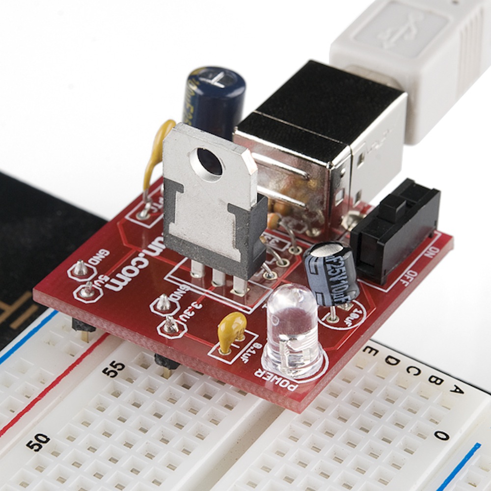
Breadboard Power Supplies
Yet another method for powering your breadboard is to use one of the many breadboard power supplies available. SparkFun carries a number of kits and boards that you can use to plug power directly into your breadboard. Some allow you to plug a wall wart directly into the breadboard. Others allow you to pull power directly from your computer via the USB connections. And, almost all of them have the capability to adjust the voltage, giving you a full range of the common voltages needed when building circuits.
Building Your First Breadboard Circuit
Now that we're familiar with the internals of a breadboard and how to provide power to them, what do we do with them? We are going to start with a simple circuit.
What You’ll Need
Here is a parts list to follow along with this circuit. If you have other electronic bits and pieces, feel free to use them and change the circuit up. Remember, there is often more ways than one to build any given circuit. Some even have dozens of different ways that you can build them.
This wish list assumes you don't have any parts/tools and is generous with quantities etc. For example, you only need one LED for this project, but the pack listed has 20 LEDs in it. The same is true with the hook-up wire. You don't need that much (or all those colors), but if you keep playing with circuits, it could come in handy. If you don't want the higher quantities check the bottom of the product pages in the section called "Related Products" and you should be able to find smaller quantities. Also, the breadboard power supply doesn't have headers, if you know how to solder and have the tools, solder the headers on yourself. If not, solderless headers have been included in the wishlist as well.
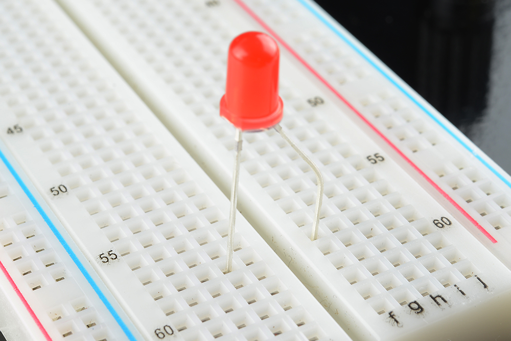
Build the Circuit
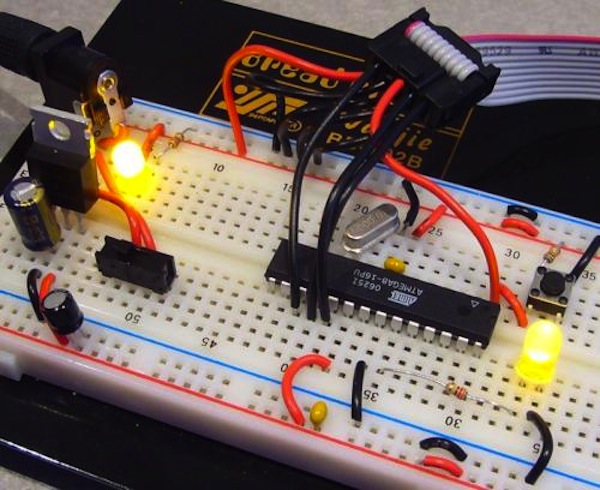
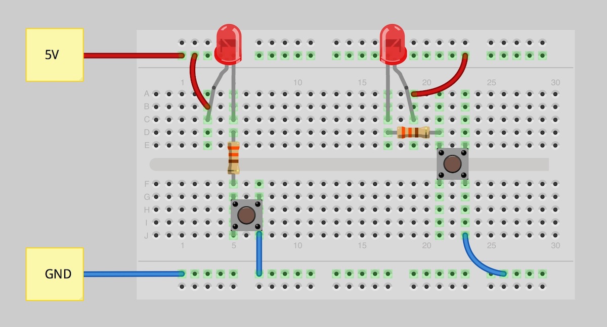
Here is a small circuit on a breadboard. The red board you see is the Breadboard Power Supply Stick with headers soldered to the PCB. The breadboard power supply stick regulates voltage from a 9V wall wart to either 5V or 3.3V to the power rails.
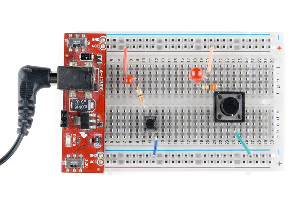
The circuit goes as follows:
There is a wire connecting the VCC power rail to the positive, anode leg of an LED.
The negative, cathode leg of the LED is connected to a 330Ω resistor.
The resistor is then connected to a button.
When the button is pushed, it connects the circuit to ground completing the circuit and turning on the LED.
Circuit Schematics
We cover how to read a schematic in another tutorial. However, it is a very important part of building circuits, so it will be covered here in short.
Schematics are universal pictograms that allow people all over the world to understand and build electronics. Every electronic component has a very unique schematic symbol. These symbols are then assembled into circuits using a variety of programs. You could also draw them out by hand. If you want to dive deeper in the world of electronics and circuit building, learning to read schematics is a very important step in doing so.
Here we have a schematic for the above circuit. Power (assuming the switch is flipped to the 5V side) is represented by the arrow at the top. It then goes to the LED (the triangle and line with arrows emitting out of it). The LED is then connected to the resistor (the squiggly line). That is connected to the button (the latch-looking symbol). Last the button is connect to ground (the horizontal line at the bottom).
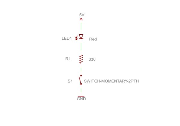
This may seem like a funny way to draw a circuit, but it is a fundamental process that has been around for decades. Schematics allow people from different nationalities and languages to build and collaborate on circuits designed by anyone. As mentioned, you can build a circuit in many different ways, but, as this schematic shows, there are certain connections that must be made. Diverging from this schematic will give you an entirely different circuit.
Practice Makes Perfect
The last bit of knowledge to leave you with is that there are tons of resources and programs you can use to build circuits without having to actually use your breadboard. One very common program used by SparkFun is Fritzing. Fritzing is a free program that allows you to build your own circuits on a virtual breadboard. It also provides schematic views for all the circuits you build. Here we can see the same circuits as above built using Fritzing.
There are many other programs like Fritzing. Some are free, and some are paid. Some will even allow you to build a circuit and test its functionality through simulations. Go explore the internet, and find the tools that work best for you.
Purchasing a Breadboard
A great way to start using breadboards is to purchase one as part of a kit. The Sparkfun Inventor's Kit includes everything you need to complete 16 different circuits.
SparkFun Inventor's Kit - v4.1
KIT-15267Breadboards
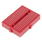
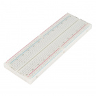
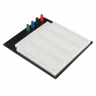
We've also listed a few basic stand-alone breadboards in different sizes for your projects.
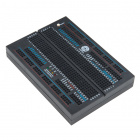
STEMTera (Black)
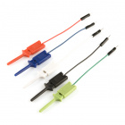
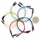
DEV-14082Jumper Wires
Looking for ways to connect easily to your boards and ICs on a breadboard? Check out the following jumper wires.
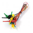
IC Hook Test Leads
CAB-00501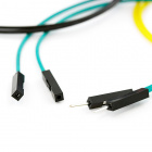

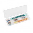
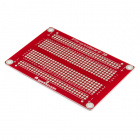
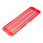
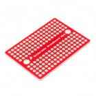
Solderable Breadboards and Protoboards
When you are finished prototyping on a breadboard, you can solder the circuit to a PCB for a more secure connection.
Interested in learning more foundational topics?
See our Engineering Essentials page for a full list of cornerstone topics surrounding electrical engineering.

Resources and Going Further
Hopefully you now have a better understanding of what a breadboard is and how it works. Now the real fun begins. We've barely scratched the surface of building circuits on breadboards. Here are some other tutorials you can check out to learn more about components and how to integrate them into your breadboard circuits.
Educators may be interested in these links.
Or, if you have mastered your circuit building skills and want to move to the next level, check out these tutorials.