Integrated Circuits
 jimblom
 Introduction
Integrated circuits (ICs) are a keystone of modern electronics. They are the heart and brains of most circuits. They are the ubiquitous little black "chips" you find on just about every circuit board. Unless you're some kind of crazy, analog electronics wizard, you're likely to have at least one IC in every electronics project you build, so it's important to understand them, inside and out.
An IC is a collection of electronic components -- resistors, transistors, capacitors, etc. -- all stuffed into a tiny chip, and connected together to achieve a common goal. They come in all sorts of flavors: single-circuit logic gates, op amps, 555 timers, voltage regulators, motor controllers, microcontrollers, microprocessors, FPGAs...the list just goes on-and-on.
Covered in this Tutorial
- The make-up of an IC
- Common IC packages
- Identifying ICs
- Commonly used ICs
Suggested Reading
Integrated circuits are one of the more fundamental concepts of electronics. They do build on some previous knowledge, though, so if you aren't familiar with these topics, consider reading their tutorials first...
What is a Circuit?
Resistors
Diodes
Polarity
Capacitors
Transistors
Inside the IC
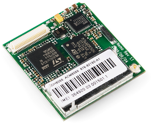
When we think integrated circuits, little black chips are what come to mind. But what's inside that black box?
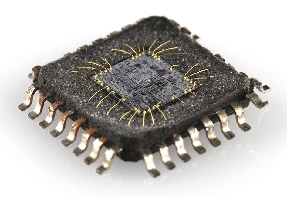
The real "meat" to an IC is a complex layering of semiconductor wafers, copper, and other materials, which interconnect to form transistors, resistors or other components in a circuit. The cut and formed combination of these wafers is called a die.
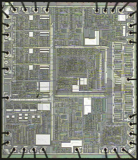
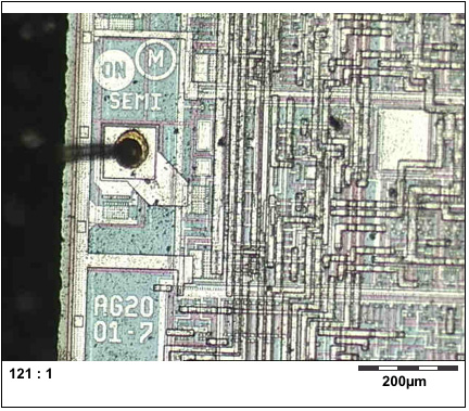
While the IC itself is tiny, the wafers of semiconductor and layers of copper it consists of are incredibly thin. The connections between the layers are very intricate. Here's a zoomed in section of the die above:
An IC die is the circuit in its smallest possible form, too small to solder or connect to. To make our job of connecting to the IC easier, we package the die. The IC package turns the delicate, tiny die, into the black chip we're all familiar with.
IC Packages
The package is what encapsulates the integrated circuit die and splays it out into a device we can more easily connect to. Each outer connection on the die is connected via a tiny piece of gold wire to a pad or pin on the package. Pins are the silver, extruding terminals on an IC, which go on to connect to other parts of a circuit. These are of utmost importance to us, because they're what will go on to connect to the rest of the components and wires in a circuit.
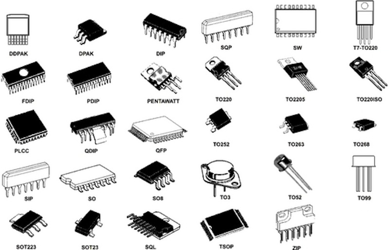
There are many different types of packages, each of which has unique dimensions, mounting-types, and/or pin-counts.
Polarity Marking and Pin Numbering
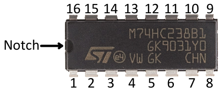
All ICs are polarized, and every pin is unique in terms of both location and function. This means the package has to have some way to convey which pin is which. Most ICs will use either a notch or a dot to indicate which pin is the first pin. (Sometimes both, sometimes one or the other.)
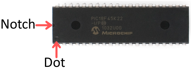
Once you know where the first pin is, the remaining pin numbers increase sequentially as you move counter-clockwise around the chip.
Mounting Style
One of the main distinguishing package type characteristics is the way they mount to a circuit board. All packages fall into one of two mounting types: through-hole (PTH) or surface-mount (SMD or SMT). Through-hole packages are generally bigger, and much easier to work with. They're designed to be stuck through one side of a board and soldered to the other side.
Surface-mount packages range in size from small to minuscule. They are all designed to sit on one side of a circuit board and be soldered to the surface. The pins of a SMD package either extrude out the side, perpendicular to the chip, or are sometimes arranged in a matrix on the bottom of the chip. ICs in this form factor are not very "hand-assembly-friendly." They usually require special tools to aid in the process.
DIP (Dual in-line packages)
DIP, short for dual in-line package, is the most common through-hole IC package you'll encounter. These little chips have two parallel rows of pins extending perpendicularly out of a rectangular, black, plastic housing.

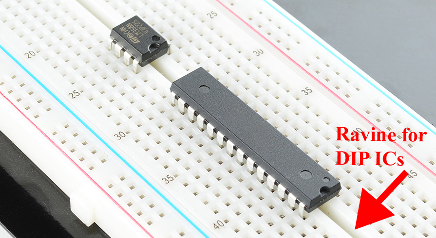
Each of the pins on a DIP IC are spaced by 0.1" (2.54mm), which is a standard spacing and perfect for fitting into breadboards and other prototyping boards. The overall dimensions of a DIP package depend on its pin count, which may be anywhere from four to 64.
The area between each row of pins is perfectly spaced to allow DIP ICs to straddle the center area of a breadboard. This provides each of the pins its own row in the board, and it makes sure they don't short to each other.
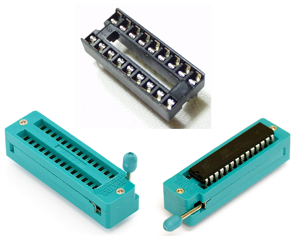
Aside from being used in breadboards, DIP ICs can also be soldered into PCBs. They're inserted into one side of the board and soldered into place on the other side. Sometimes, instead of soldering directly to the IC, it's a good idea to socket the chip. Using sockets allows for a DIP IC to be removed and swapped out, if it happens to "let its blue smoke out."
Surface-Mount (SMD/SMT) Packages
There is a huge variety of surface-mount package types these days. In order to work with surface-mount packaged ICs, you usually need a custom printed circuit board (PCB) made for them, which has a matching pattern of copper on which they're soldered.
Here are a few of the more common SMD package types out there, ranging in hand-solderability from "doable" to "doable, but only with special tools" to "doable only with very special, usually automated tools".
Small-Outline (SOP)
Small-outline IC (SOIC) packages are the surface-mount cousin of the DIP. It's what you'd get if you bent all the pins on a DIP outward, and shrunk it down to size. With a steady hand, and a close eye, these packages are among the easiest SMD parts to hand solder. On SOIC packages, each pin is usually spaced by about 0.05" (1.27mm) from the next.
The SSOP (shrink small-outline package) is an even smaller version of SOIC packages. Other, similar IC packages include TSOP (thin small-outline package) and TSSOP (thin-shrink small-outline package).

A lot of the more simple, single-task-oriented ICs like the MAX232 or multiplexers come in SOIC or SSOP forms.
Quad Flat Packages
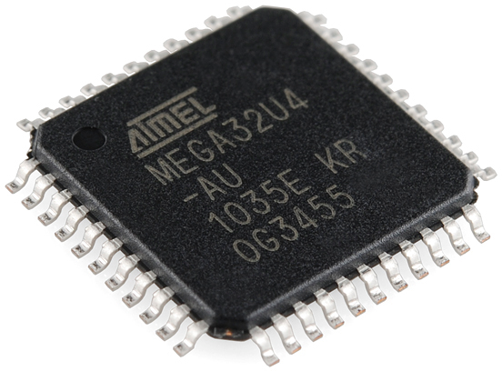
Splaying IC pins out in all four directions gets you something that might look like a quad flat package (QFP). QFP ICs might have anywhere from eight pins per side (32 total) to upwards of seventy (300+ total). The pins on a QFP IC are usually spaced by anywhere from 0.4mm to 1mm. Smaller variants of the standard QFP package include thin (TQFP), very thin (VQFP), and low-profile (LQFP) packages.
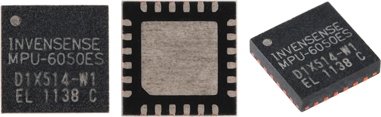
If you sanded the legs off a QFP IC, you get something that might look like a quad-flat no-leads (QFN) package. The connections on QFN packages are tiny, exposed pads on the bottom corner edges of the IC. Sometimes they wrap around, and are exposed on both the side and bottom, other packages only expose the pad on the bottom of the chip.
Thin (TQFN), very thin (VQFN), and micro-lead (MLF) packages are smaller variations of the standard QFN package. There are even dual no-lead (DFN) and thin-dual no-lead (TDFN) packages, which have pins on just two of the sides.
Many microprocessors, sensors, and other modern ICs come in QFP or QFN packages. The popular ATmega328 microcontroller is offered in both a TQFP package and a QFN-type (MLF) form, while a tiny accelerometer/gyroscope like the MPU-6050 comes in a miniscule QFN form.
Ball Grid Arrays
Finally, for really advanced ICs, there are ball grid array (BGA) packages. These are amazingly intricate little packages where little balls of solder are arranged in a 2-D grid on the bottom of the IC. Sometimes the solder balls are attached directly to the die!
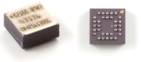
BGA packages are usually reserved for advanced microprocessors, like those on the pcDuino or Raspberry Pi.
If you can hand solder a BGA-packaged IC, consider yourself a master solderer. Usually, to put these packages onto a PCB requires an automated procedure involving pick-and-place machines and reflow ovens.
Common ICs
Integrated circuits are prevalent in so many forms across electronics, it's hard to cover everything. Here are a few of the more common ICs you might encounter in educational electronics.
Logic Gates, Timers, Shift Registers, Etc.
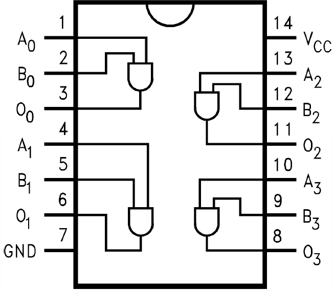
Logic gates, the building blocks of much more ICs themselves, can be packaged into their own integrated circuit. Some logic gate ICs might contain a handful of gates in one package, like this quad-input AND gate:
Logic gates can be connected inside an IC to create timers, counters, latches, shift registers, and other basic logic circuitry. Most of these simple circuits can be found in DIP packages, as well as SOIC and SSOP.
Microcontrollers, Microprocessors, FPGAs, Etc.
Microcontrollers, microprocessors, and FPGAs, all packing thousands, millions, even billions of transistors into a tiny chip, are all integrated circuits. These components exist in a wide range in functionality, complexity, and size; from an 8-bit microcontroller like the ATmega328 in an Arduino, to a complex 64-bit, multi-core microprocessor organizing activity in your computer.
These components are usually the largest IC in a circuit. Simple microcontrollers can be found in packages ranging from DIP to QFN/QFP, with pin counts lying somewhere between eight and a hundred. As these components grow in complexity, the package gets equally complex. FPGAs and complex microprocessors can have upwards of a thousand pins and are only available in advanced packages like QFN, LGA, or BGA.
Sensors
Modern digital sensors, like temperature sensors, accelerometers, and gyroscopes all come packed into an integrated circuit.
These ICs are usually smaller than the microcontrollers, or other ICs on a circuit board, with pin counts in the three to twenty range. DIP sensor ICs are becoming a rarity, as modern components are usually found in QFP, QFN, even BGA packages.
Resources and Going Further
Integrated circuits are present in just about every circuit out there. Now that you're familiar with ICs, why not check out some of these related concept tutorials:
- PCB Basics - ICs have to be connected to a circuit somehow. Usually we'll solder an IC to a printed circuit board (PCB). Check out this tutorial to learn more about those little green boards.
- Serial Communication, Serial Peripheral Interface (SPI), and I2C - All three of these are communication protocols ICs use to communicate between each other.
Or, check out some of these skill tutorials. These are handy skills every budding electronics hacker should learn!
- How to Solder - Unless you're using a breadboard with your ICs, you'll probably need to solder them.
- 8-Pin SOIC to DIP Adapter Hookup Guide - An example of soldering a 8-pin SOIC package to breakout board.
- SSOP-16 to DIP Adapter Hookup Guide - Another example of soldering a 16-pin SOIC package to breakout board.
- Designing PCBs - Or, if you're already familiar with PCBs, why not try making one! This tutorial explains how to use a freely available software (Eagle) to design PCBs.
- Designing PCB Footprints - This tutorial walks you through the steps required to design a PCB footprint for an IC, using Eagle CAD.
- Making Custom Footprints in EAGLE - Making a custom footprint in Eagle with a picture.
How to Solder: Through-Hole Soldering
Designing PCBs: Advanced SMD
Designing PCBs: SMD Footprints
Making Custom Footprints in EAGLE
8-Pin SOIC to DIP Adapter Hookup Guide
SSOP-16 to DIP Adapter Hookup Guide
Interested in learning more foundational topics?
See our Engineering Essentials page for a full list of cornerstone topics surrounding electrical engineering.
