Capacitors
 jimblom
 Introduction
A capacitor is a two-terminal, electrical component. Along with resistors and inductors, they are one of the most fundamental passive components we use. You would have to look very hard to find a circuit which didn't have a capacitor in it.
What makes capacitors special is their ability to store energy; they're like a fully charged electric battery. Caps, as we usually refer to them, have all sorts of critical applications in circuits. Common applications include local energy storage, voltage spike suppression, and complex signal filtering.
Covered in this Tutorial
In this tutorial, we'll be examining all sorts of capacitor-related topics, including:
- How a capacitor is made
- How a capacitor works
- Units of capacitance
- Types of capacitors
- How to recognize capacitors
- How capacitance combines in series and parallel
- Common capacitor applications
Suggested Reading
Some of the concepts in this tutorial build on previous electronics knowledge. Before jumping into this tutorial, consider reading (at least skimming) these first:
- What is Electricity?
- Voltage, Current, Resistance, and Ohm's Law
- What is a Circuit
- Series vs. Parallel Circuits
- How to Use A Multimeter
- Metric Prefixes
Symbols and Units
Circuit Symbols
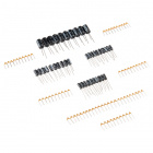
There are two common ways to draw a capacitor in a schematic. They always have two terminals, which go on to connect to the rest of the circuit. The capacitors symbol consists of two parallel lines, which are either flat or curved; both lines should be parallel to each other, close, but not touching (this is actually representative of how the capacitor is made. Hard to describe, easier to just show:
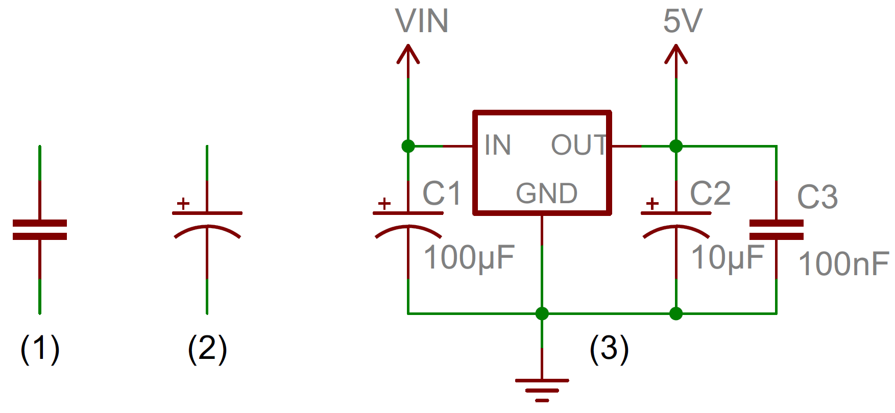
The symbol with the curved line (#2 in the photo above) indicates that the capacitor is polarized, meaning it's probably an electrolytic capacitor. More on that in the types of capacitors section of this tutorial.
Each capacitor should be accompanied by a name -- C1, C2, etc.. -- and a value. The value should indicate the capacitance of the capacitor; how many farads it has. Speaking of farads...
Capacitance Units
Not all capacitors are created equal. Each capacitor is built to have a specific amount of capacitance. The capacitance of a capacitor tells you how much charge it can store, more capacitance means more capacity to store charge. The standard unit of capacitance is called the farad, which is abbreviated F.
It turns out that a farad is a lot of capacitance, even 0.001F (1 milifarad -- 1mF) is a big capacitor. Usually you'll see capacitors rated in the pico- (10-12) to microfarad (10-6) range.
| Prefix Name | Abbreviation | Weight | Equivalent Farads |
|---|---|---|---|
| Picofarad | pF | 10-12 | 0.000000000001 F |
| Nanofarad | nF | 10-9 | 0.000000001 F |
| Microfarad | µF | 10-6 | 0.000001 F |
| Milifarad | mF | 10-3 | 0.001 F |
| Kilofarad | kF | 103 | 1000 F |
When you get into the farad to kilofarad range of capacitance, you start talking about special caps called super or ultra-capacitors.
Capacitor Theory
Note: The stuff on this page isn't completely critical for electronics beginners to understand...and it gets a little complicated towards the end. We recommend reading the How a Capacitor is Made section, the others could probably be skipped if they give you a headache.
How a Capacitor Is Made
The schematic symbol for a capacitor actually closely resembles how it's made. A capacitor is created out of two metal plates and an insulating material called a dielectric. The metal plates are placed very close to each other, in parallel, but the dielectric sits between them to make sure they don't touch.
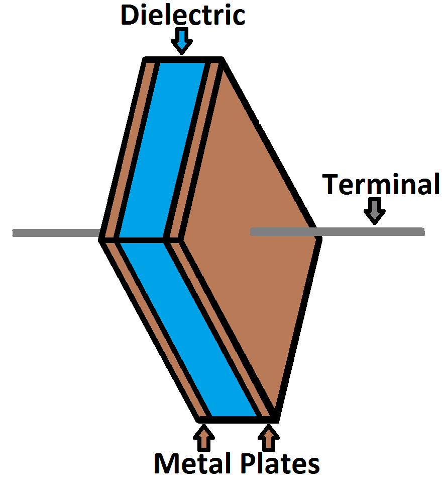
The dielectric can be made out of all sorts of insulating materials: paper, glass, rubber, ceramic, plastic, or anything that will impede the flow of current.
The plates are made of a conductive material: aluminum, tantalum, silver, or other metals. They're each connected to a terminal wire, which is what eventually connects to the rest of the circuit.
The capacitance of a capacitor -- how many farads it has -- depends on how it's constructed. More capacitance requires a larger capacitor. Plates with more overlapping surface area provide more capacitance, while more distance between the plates means less capacitance. The material of the dielectric even has an effect on how many farads a cap has. The total capacitance of a capacitor can be calculated with the equation:
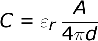
Where εr is the dielectric's relative permittivity (a constant value determined by the dielectric material), A is the amount of area the plates overlap each other, and d is the distance between the plates.
How a Capacitor Works
Electric current is the flow of electric charge, which is what electrical components harness to light up, or spin, or do whatever they do. When current flows into a capacitor, the charges get "stuck" on the plates because they can't get past the insulating dielectric. Electrons -- negatively charged particles -- are sucked into one of the plates, and it becomes overall negatively charged. The large mass of negative charges on one plate pushes away like charges on the other plate, making it positively charged.
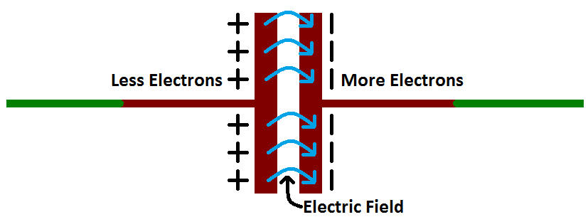
The positive and negative charges on each of these plates attract each other, because that's what opposite charges do. But, with the dielectric sitting between them, as much as they want to come together, the charges will forever be stuck on the plate (until they have somewhere else to go). The stationary charges on these plates create an electric field, which influence electric potential energy and voltage. When charges group together on a capacitor like this, the cap is storing electric energy just as a battery might store chemical energy.
Charging and Discharging
When positive and negative charges coalesce on the capacitor plates, the capacitor becomes charged. A capacitor can retain its electric field -- hold its charge -- because the positive and negative charges on each of the plates attract each other but never reach each other.
At some point the capacitor plates will be so full of charges that they just can't accept any more. There are enough negative charges on one plate that they can repel any others that try to join. This is where the capacitance (farads) of a capacitor comes into play, which tells you the maximum amount of charge the cap can store.
If a path in the circuit is created, which allows the charges to find another path to each other, they'll leave the capacitor, and it will discharge.
For example, in the circuit below, a battery can be used to induce an electric potential across the capacitor. This will cause equal but opposite charges to build up on each of the plates, until they're so full they repel any more current from flowing. An LED placed in series with the cap could provide a path for the current, and the energy stored in the capacitor could be used to briefly illuminate the LED.
Calculating Charge, Voltage, and Current
A capacitor's capacitance -- how many farads it has -- tells you how much charge it can store. How much charge a capacitor is currently storing depends on the potential difference (voltage) between its plates. This relationship between charge, capacitance, and voltage can be modeled with this equation:

The capacitance of a capacitor should always be a constant, known value. So we can adjust voltage to increase or decrease the cap's charge. More voltage means more charge, less voltage...less charge.
That equation also gives us a good way to define the value of one farad. One farad (F) is the capacity to store one unit of energy (coulombs) per every one volt.
Calculating Current
We can take the charge/voltage/capacitance equation a step further to find out how capacitance and voltage affect current, because current is the rate of flow of charge. The gist of a capacitor's relationship to voltage and current is this: the amount of current through a capacitor depends on both the capacitance and how quickly the voltage is rising or falling. If the voltage across a capacitor swiftly rises, a large positive current will be induced through the capacitor. A slower rise in voltage across a capacitor equates to a smaller current through it. If the voltage across a capacitor is steady and unchanging, no current will go through it.
(This is ugly, and gets into calculus. It's not all that necessary until you get into time-domain analysis, filter-design, and other gnarly stuff, so skip ahead to the next page if you're not comfortable with this equation.) The equation for calculating current through a capacitor is:
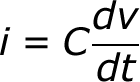
The dV/dt part of that equation is a derivative (a fancy way of saying instantaneous rate) of voltage over time, it's equivalent to saying "how fast is voltage going up or down at this very moment". The big takeaway from this equation is that if voltage is steady, the derivative is zero, which means current is also zero. This is why current cannot flow through a capacitor holding a steady, DC voltage.
Types of Capacitors
There are all sorts of capacitor types out there, each with certain features and drawbacks which make it better for some applications than others.
When deciding on capacitor types there are a handful of factors to consider:
- Size - Size both in terms of physical volume and capacitance. It's not uncommon for a capacitor to be the largest component in a circuit. They can also be very tiny. More capacitance typically requires a larger capacitor.
- Maximum voltage - Each capacitor is rated for a maximum voltage that can be dropped across it. Some capacitors might be rated for 1.5V, others might be rated for 100V. Exceeding the maximum voltage will usually result in destroying the capacitor.
- Leakage current - Capacitors aren't perfect. Every cap is prone to leaking some tiny amount of current through the dielectric, from one terminal to the other. This tiny current loss (usually nanoamps or less) is called leakage. Leakage causes energy stored in the capacitor to slowly, but surely drain away.
- Equivalent series resistance (ESR) - The terminals of a capacitor aren't 100% conductive, they'll always have a tiny amount of resistance (usually less than 0.01Ω) to them. This resistance becomes a problem when a lot of current runs through the cap, producing heat and power loss.
- Tolerance - Capacitors also can't be made to have an exact, precise capacitance. Each cap will be rated for their nominal capacitance, but, depending on the type, the exact value might vary anywhere from ±1% to ±20% of the desired value.
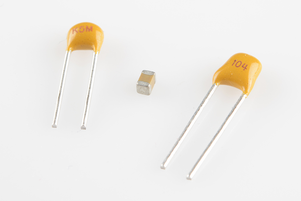
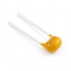
Ceramic Capacitors
The most commonly used and produced capacitor out there is the ceramic capacitor. The name comes from the material from which their dielectric is made.
Ceramic capacitors are usually both physically and capacitance-wise small. It's hard to find a ceramic capacitor much larger than 10µF. A surface-mount ceramic cap is commonly found in a tiny 0402 (0.4mm x 0.2mm), 0603 (0.6mm x 0.3mm) or 0805 package. Through-hole ceramic caps usually look like small (commonly yellow or red) bulbs, with two protruding terminals.
Compared to the equally popular electrolytic caps, ceramics are a more near-ideal capacitor (much lower ESR and leakage currents), but their small capacitance can be limiting. They are usually the least expensive option too. These caps are well-suited for high-frequency coupling and decoupling applications.
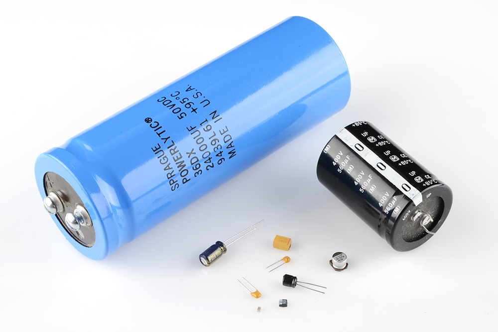
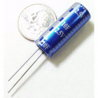
Aluminum and Tantalum Electrolytic
Electrolytics are great because they can pack a lot of capacitance into a relatively small volume. If you need a capacitor in the range of 1µF-1mF, you're most likely to find it in an electrolytic form. They're especially well suited to high-voltage applications because of their relatively high maximum voltage ratings.
Aluminum electrolytic capacitors, the most popular of the electrolytic family, usually look like little tin cans, with both leads extending from the bottom.
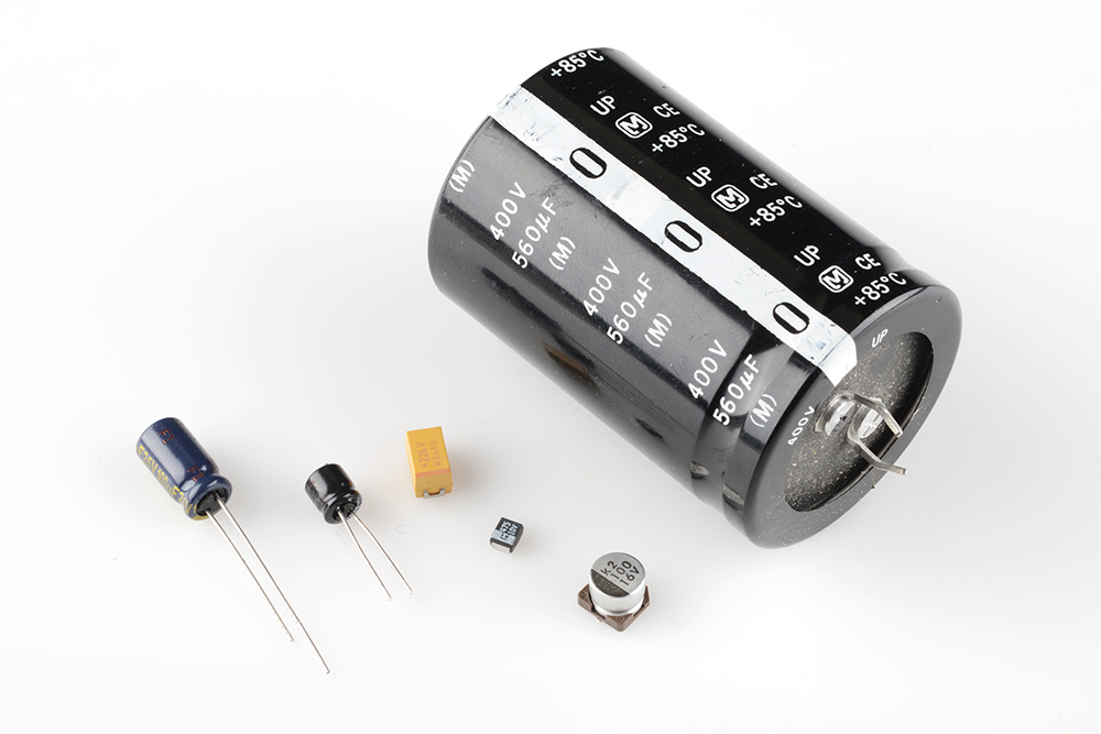
Unfortunately, electrolytic caps are usually polarized. They have a positive pin -- the anode -- and a negative pin called the cathode. When voltage is applied to an electrolytic cap, the anode must be at a higher voltage than the cathode. The cathode of an electrolytic capacitor is usually identified with a '-' marking, and a colored strip on the case. The leg of the anode might also be slightly longer as another indication. If voltage is applied in reverse on an electrolytic cap, they'll fail spectacularly (making a pop and bursting open), and permanently. After popping an electrolytic will behave like a short circuit.
These caps also notorious for leakage -- allowing small amounts of current (on the order of nA) to run through the dielectric from one terminal to the other. This makes electrolytic caps less-than-ideal for energy storage, which is unfortunate given their high capacity and voltage rating.
Supercapacitors
If you're looking for a capacitor made to store energy, look no further than supercapacitors. These caps are uniquely designed to have very high capacitances, in the range of farads.
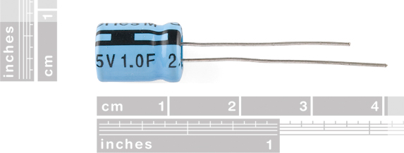
While they can store a huge amount of charge, supercaps can't deal with very high voltages. This 10F supercap is only rated for 2.5V max. Any more than that will destroy it. Super caps are commonly placed in series to achieve a higher voltage rating (while reducing total capacitance).
The main application for supercapacitors is in storing and releasing energy, like batteries, which are their main competition. While supercaps can't hold as much energy as an equally sized battery, they can release it much faster, and they usually have a much longer lifespan.
Others
Electrolytic and ceramic caps cover about 80% of the capacitor types out there (and supercaps only about 2%, but they're super!). Another common capacitor type is the film capacitor, which features very low parasitic losses (ESR), making them great for dealing with very high currents.
There's plenty of other less common capacitors. Variable capacitors can produce a range of capacitances, which makes them a good alternative to variable resistors in tuning circuits. Twisted wires or PCBs can create capacitance (sometimes undesired) because each consists of two conductors separated by an insulator. Leyden Jars -- a glass jar filled with and surrounded by conductors -- are the O.G. of the capacitor family. Finally, of course, flux capacitors (a strange combination of inductor and capacitor) are critical if you ever plan on traveling back to the glory days.
Capacitors in Series/Parallel
Much like resistors, multiple capacitors can be combined in series or parallel to create a combined equivalent capacitance. Capacitors, however, add together in a way that's completely the opposite of resistors.
Capacitors in Parallel
When capacitors are placed in parallel with one another the total capacitance is simply the sum of all capacitances. This is analogous to the way resistors add when in series.
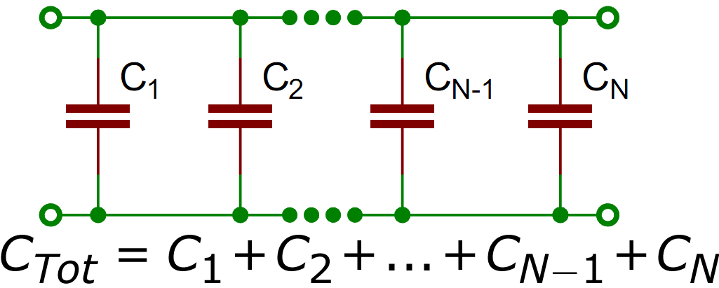
So, for example, if you had three capacitors of values 10µF, 1µF, and 0.1µF in parallel, the total capacitance would be 11.1µF (10+1+0.1).
Capacitors in Series
Much like resistors are a pain to add in parallel, capacitors get funky when placed in series. The total capacitance of N capacitors in series is the inverse of the sum of all inverse capacitances.
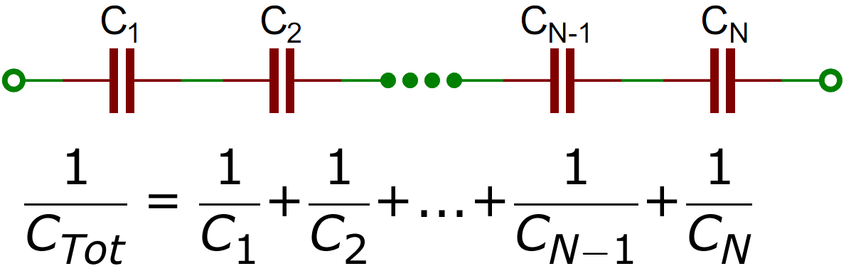
If you only have two capacitors in series, you can use the "product-over-sum" method to calculate the total capacitance:
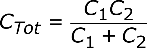
Taking that equation even further, if you have two equal-valued capacitors in series, the total capacitance is half of their value. For example two 10F supercapacitors in series will produce a total capacitance of 5F (it'll also have the benefit of doubling the voltage rating of the total capacitor, from 2.5V to 5V).
Application Examples
There are tons of applications for this nifty little (actually they're usually pretty large) passive component. To give you an idea of their wide range of uses, here are a few examples:
Decoupling (Bypass) Capacitors
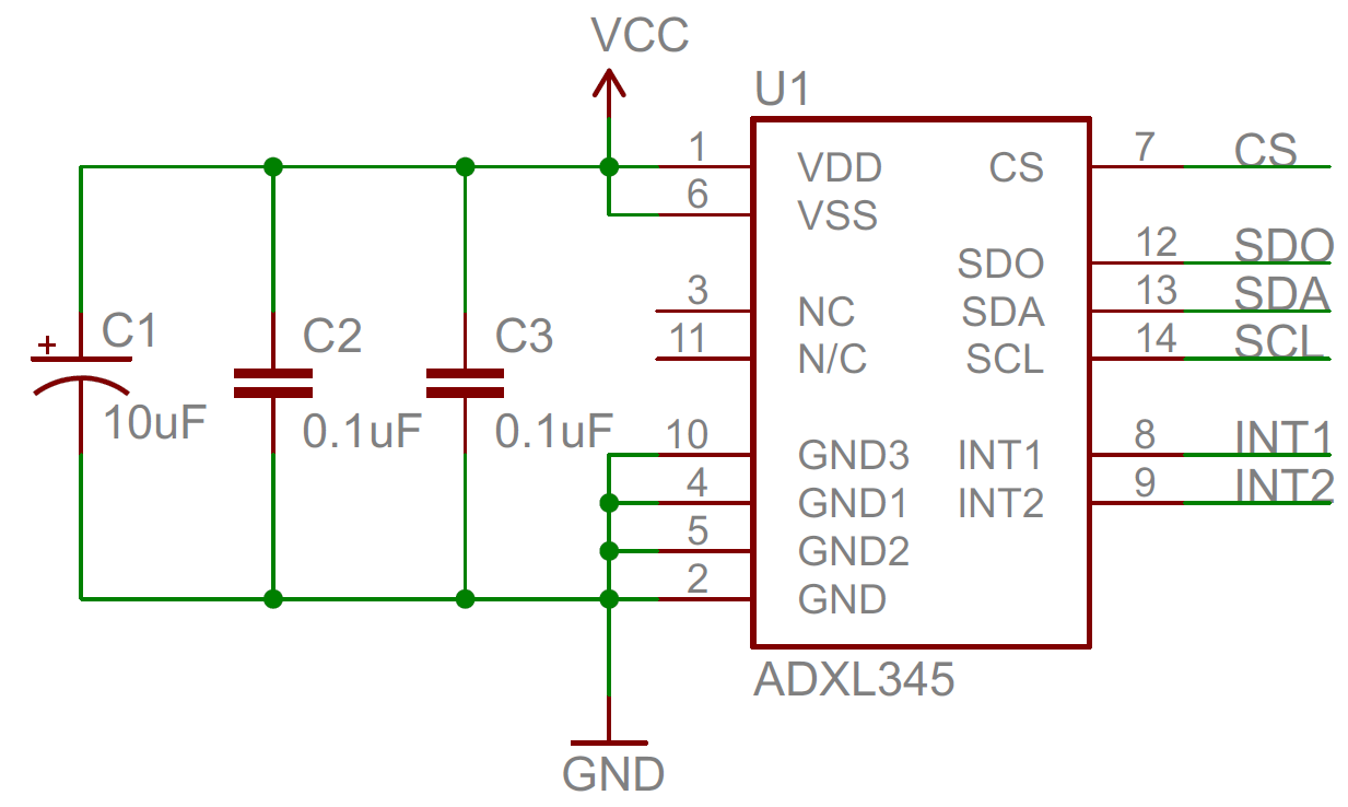
A lot of the capacitors you see in circuits, especially those featuring an integrated circuit, are decoupling. A decoupling capacitor's job is to supress high-frequency noise in power supply signals. They take tiny voltage ripples, which could otherwise be harmful to delicate ICs, out of the voltage supply.
In a way, decoupling capacitors act as a very small, local power supply for ICs (almost like an uninterruptible power supply is to computers). If the power supply very temporarily drops its voltage (which is actually pretty common, especially when the circuit it's powering is constantly switching its load requirements), a decoupling capacitor can briefly supply power at the correct voltage. This is why these capacitors are also called bypass caps; they can temporarily act as a power source, bypassing the power supply.
Decoupling capacitors connect between the power source (5V, 3.3V, etc.) and ground. It's not uncommon to use two or more different-valued, even different types of capacitors to bypass the power supply, because some capacitor values will be better than others at filtering out certain frequencies of noise.
While it seems like this might create a short from power to ground, only high-frequency signals can run through the capacitor to ground. The DC signal will go to the IC, just as desired. Another reason these are called bypass capacitors is because the high frequencies (in the kHz-MHz range) bypass the IC, instead running through the capacitor to get to ground.
When physically placing decoupling capacitors, they should always be located as close as possible to an IC. The further away they are, they less effective they'll be.
To follow good engineering practice, always add at least one decoupling capacitor to every IC. Usually 0.1µF is a good choice, or even add some 1µF or 10µF caps. They're a cheap addition, and they help make sure the chip isn't subjected to big dips or spikes in voltage.
Power Supply Filtering
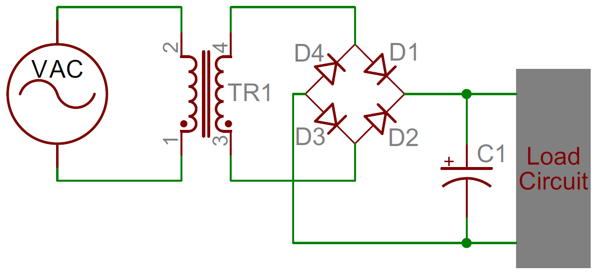
Diode rectifiers can be used to turn the AC voltage coming out of your wall into the DC voltage required by most electronics. But diodes alone can't turn an AC signal into a clean DC signal, they need the help of capacitors! By adding a parallel capacitor to a bridge rectifier, a rectified signal like this:
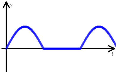
Can be turned into a near-level DC signal like this:
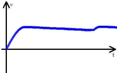
Capacitors are stubborn components, they'll always try to resist sudden changes in voltage. The filter capacitor will charge up as the rectified voltage increases. When the rectified voltage coming into the cap starts its rapid decline, the capacitor will access its bank of stored energy, and it'll discharge very slowly, supplying energy to the load. The capacitor shouldn't fully discharge before the input rectified signal starts to increase again, recharging the cap. This dance plays out many times a second, over-and-over as long as the power supply is in use.
If you tear apart any AC-to-DC power supply, you're bound to find at least one rather large capacitor. Below are the guts of a 9V DC wall adapter. Notice any capacitors in there?

There might be more capacitors than you think! There are four electrolytic, tin-can-looking caps ranging from 47µF to 1000µF. The big, yellow rectangle in the foreground is a high-voltage 0.1µF polypropylene film cap. The blue disc-shaped cap and the little green one in the middle are both ceramics.
Energy Storage and Supply
It seems obvious that if a capacitor stores energy, one of it's many applications would be supplying that energy to a circuit, just like a battery. The problem is capacitors have a much lower energy density than batteries; they just can't pack as much energy as an equally sized chemical battery (but that gap is narrowing!).
The upside of capacitors is they usually lead longer lives than batteries, which makes them a better choice environmentally. They're also capable of delivering energy much faster than a battery, which makes them good for applications which need a short, but high burst of power. A camera flash might get its power from a capacitor (which, in turn, was probably charged by a battery).
| Battery | Capacitor | |
|---|---|---|
| Capacity | ✓ | |
| Energy Density | ✓ | |
| Charge/Discharge Rate | ✓ | |
| Life Span | ✓ |
Signal Filtering
Capacitors have a unique response to signals of varying frequencies. They can block out low-frequency or DC signal-components while allowing higher frequencies to pass right through. They're like a bouncer at a very exclusive club for high frequencies only.
Filtering signals can be useful in all sorts of signal processing applications. Radio receivers might use a capacitor (among other components) to tune out undesired frequencies.
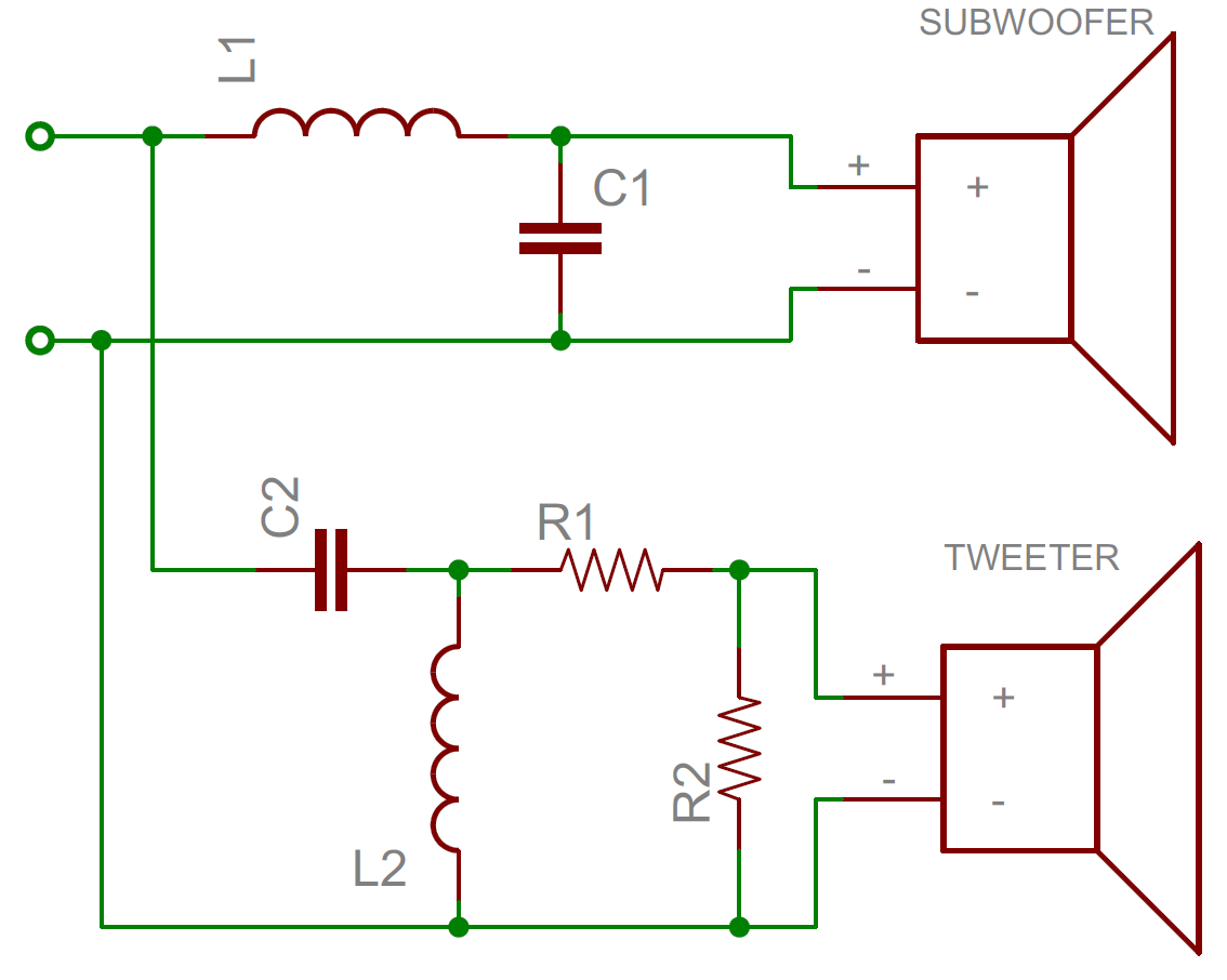
Another example of capacitor signal filtering is passive crossover circuits inside speakers, which separate a single audio signal into many. A series capacitor will block out low frequencies, so the remaining high-frequency parts of the signal can go to the speaker's tweeter. In the low-frequency passing, subwoofer circuit, high-frequencies can mostly be shunted to ground through the parallel capacitor.
De-rating
When working with capacitors, it's important to design your circuits with capacitors that have a much higher tolerance than the potentially highest voltage spike in your system.
Here's an excellent video from SparkFun Engineer Shawn about what happens to different types of capacitors when you fail to de-rate your capacitors and exceed their maximum voltage specs. You can read more about his experiments here.
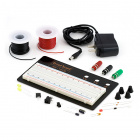
Purchasing Capacitors
Store up on these little energy storage components or put them to work a beginning power supply kit.
Our recommendations:
Interested in learning more foundational topics?
See our Engineering Essentials page for a full list of cornerstone topics surrounding electrical engineering.

Resources and Going Further
Whew. Feel like a capacitor expert?! Want to keep learning more about the fundamentals of electronics? If you haven't already, consider reading about some of the other common electronics components:
Or maybe some of these tutorials will catch your attention?