How to Use a Multimeter
This Tutorial is Retired!
This tutorial covers concepts or technologies that are no longer current. It's still here for you to read and enjoy, but may not be as useful as our newest tutorials.
 Nate
Nate Introduction
So... how do I use a multimeter? This tutorial will show you how to use a digital multimeter (DMM), an indispensable tool that you can use to diagnose circuits, learn about other people's electronic designs, and even test a battery. Hence the 'multi'-'meter' (multiple measurement) name.
The most basic things we measure are voltage and current. A multimeter is also great for some basic sanity checks and troubleshooting. Is your circuit not working? Does the switch work? Put a meter on it! The multimeter is your first defense when troubleshooting a system. In this tutorial we will cover measuring voltage, current, resistance and continuity.
Suggested Reading
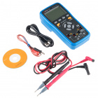
These concepts may be helpful with this tutorial:We will be using the SparkFun VC830L throughout the tutorial, but these methods should apply to most multimeters.
Video
Looking for the Multimeter that's right for you?
We've got you covered!
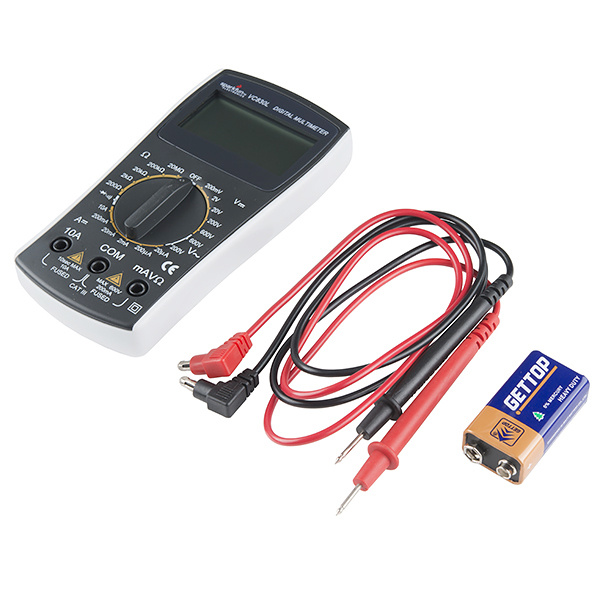
Parts of a Multimeter
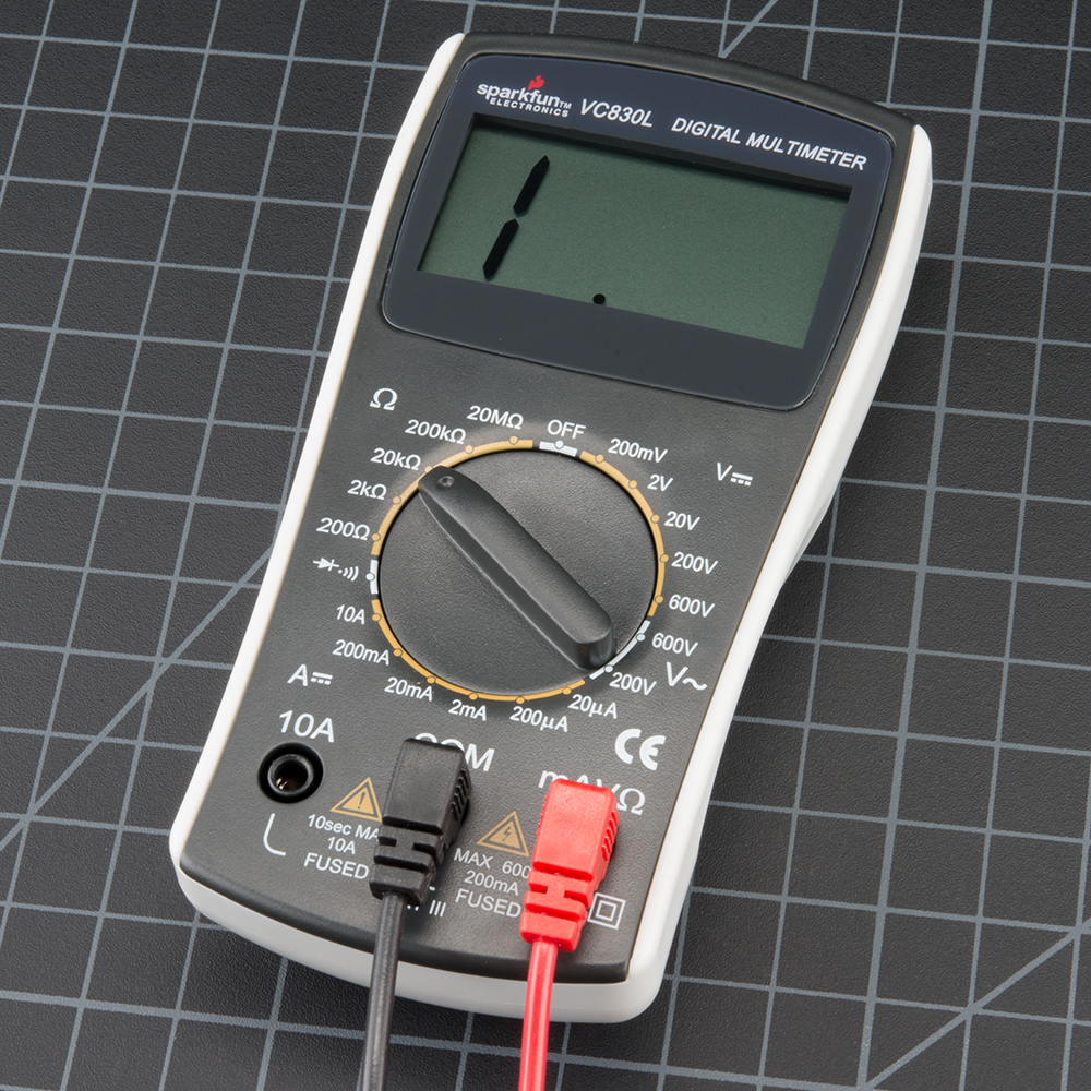
A multimeter is has three parts:
- Display
- Selection Knob
- Ports
The display usually has four digits and the ability to display a negative sign. A few multimeters have illuminated displays for better viewing in low light situations.
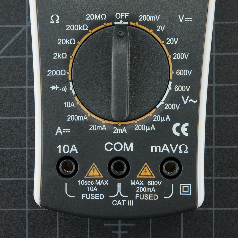
The selection knob allows the user to set the multimeter to read different things such as milliamps (mA) of current, voltage (V) and resistance (Ω).
Two probes are plugged into two of the ports on the front of the unit. COM stands for common and is almost always connected to Ground or ‘-’ of a circuit. The COM probe is conventionally black but there is no difference between the red probe and black probe other than color. 10A is the special port used when measuring large currents (greater than 200mA). mAVΩ is the port that the red probe is conventionally plugged in to. This port allows the measurement of current (up to 200mA), voltage (V), and resistance (Ω). The probes have a banana type connector on the end that plugs into the multimeter. Any probe with a banana plug will work with this meter. This allows for different types of probes to be used.
Probe Types
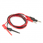
There are many different types of probes available for multimeters. Here are a few of our favorites:
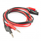
- Banana to Alligator Clips : These are great cables for connecting to large wires or pins on a breadboard. Good for performing longer term tests where you don’t have to have to hold the probes in place while you manipulate a circuit.
- Banana to IC Hook : IC hooks work well on smaller ICs and legs of ICs.
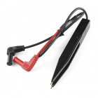
- Banana to Tweezers : Tweezers are handy if you are needing to test SMD components.
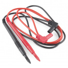
- Banana to Test Probes : If you ever break a probe, they are cheap to replace!
Multimeter Probes - Tweezers
TOL-11060Measuring Voltage
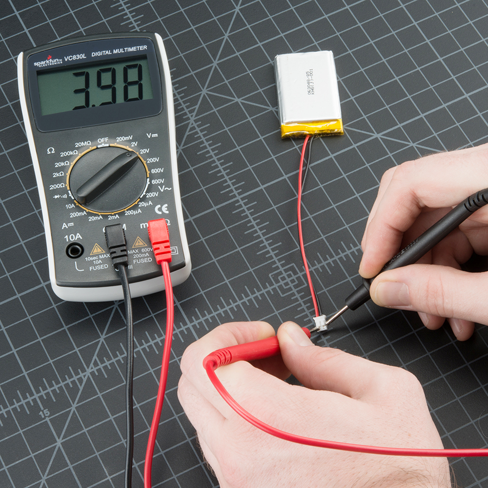
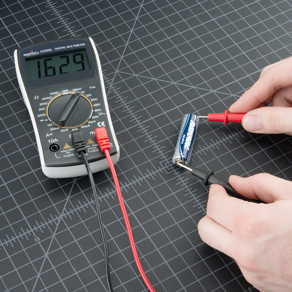
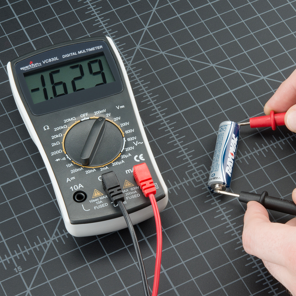
To start, let's measure voltage on a AA battery: Plug the black probe into COM and the red probe into mAVΩ. Set the multimeter to "2V" in the DC (direct current) range. Almost all portable electronics use direct current), not alternating current. Connect the black probe to the battery's ground or '-' and the red probe to power or '+'. Squeeze the probes with a little pressure against the positive and negative terminals of the AA battery. If you've got a fresh battery, you should see around 1.5V on the display (this battery is brand new, so its voltage is slightly higher than 1.5V).
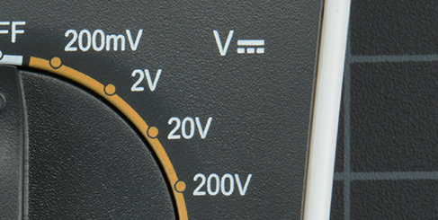
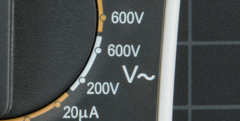
If you're measuring DC voltage (such as a battery or a sensor hooked up to an Arduino) you want to set the knob where the V has a straight line. AC voltage (like what comes out of the wall) can be dangerous, so we rarely need to use the AC voltage setting (the V with a wavy line next to it). If you're messing with AC, we recommend you get a non-contact tester rather than use a digital multimeter.
What happens if you switch the red and black probes? The reading on the multimeter is simply negative. Nothing bad happens! The multimeter measures voltage in relation to the common probe. How much voltage is there on the ‘+’ of the battery compared to common or the negative pin? 1.5V. If we switch the probes, we define ‘+’ as the common or zero point. How much voltage is there on the ‘-’ of the battery compared to our new zero? -1.5V!
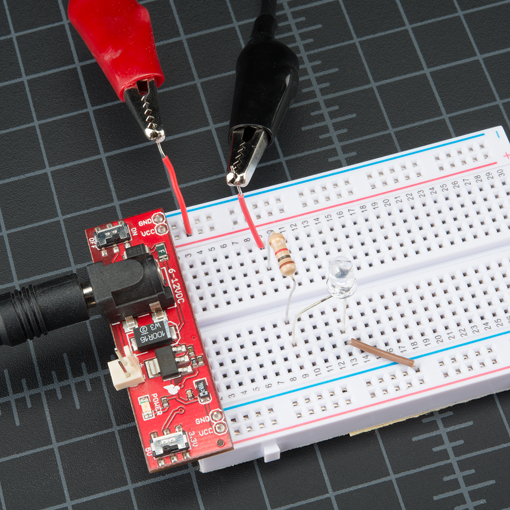
Now let's construct a simple circuit to demonstrate how to measure voltage in a real world scenario. The circuit is simply a 1kΩ and a Blue super bright LED powered with a SparkFun Breadboard Power Supply Stick. To begin, let's make sure the circuit you are working on is powered up correctly. If your project should be at 5V but is less than 4.5V or greater than 5.5V, this would quickly give you an indication that something is wrong and you may need to check your power connections or the wiring of your circuit.
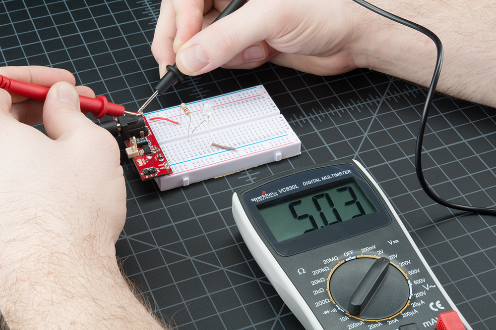
Set the knob to "20V" in the DC range (the DC Voltage range has a V with a straight line next to it). Multimeters are generally not autoranging. You have to set the multimeter to a range that it can measure. For example, 2V measures voltages up to 2 volts, and 20V measures voltages up to 20 volts. So if you've measuring a 12V battery, use the 20V setting. 5V system? Use the 20V setting. If you set it incorrectly, you will probably see the meter screen change and then read '1'.
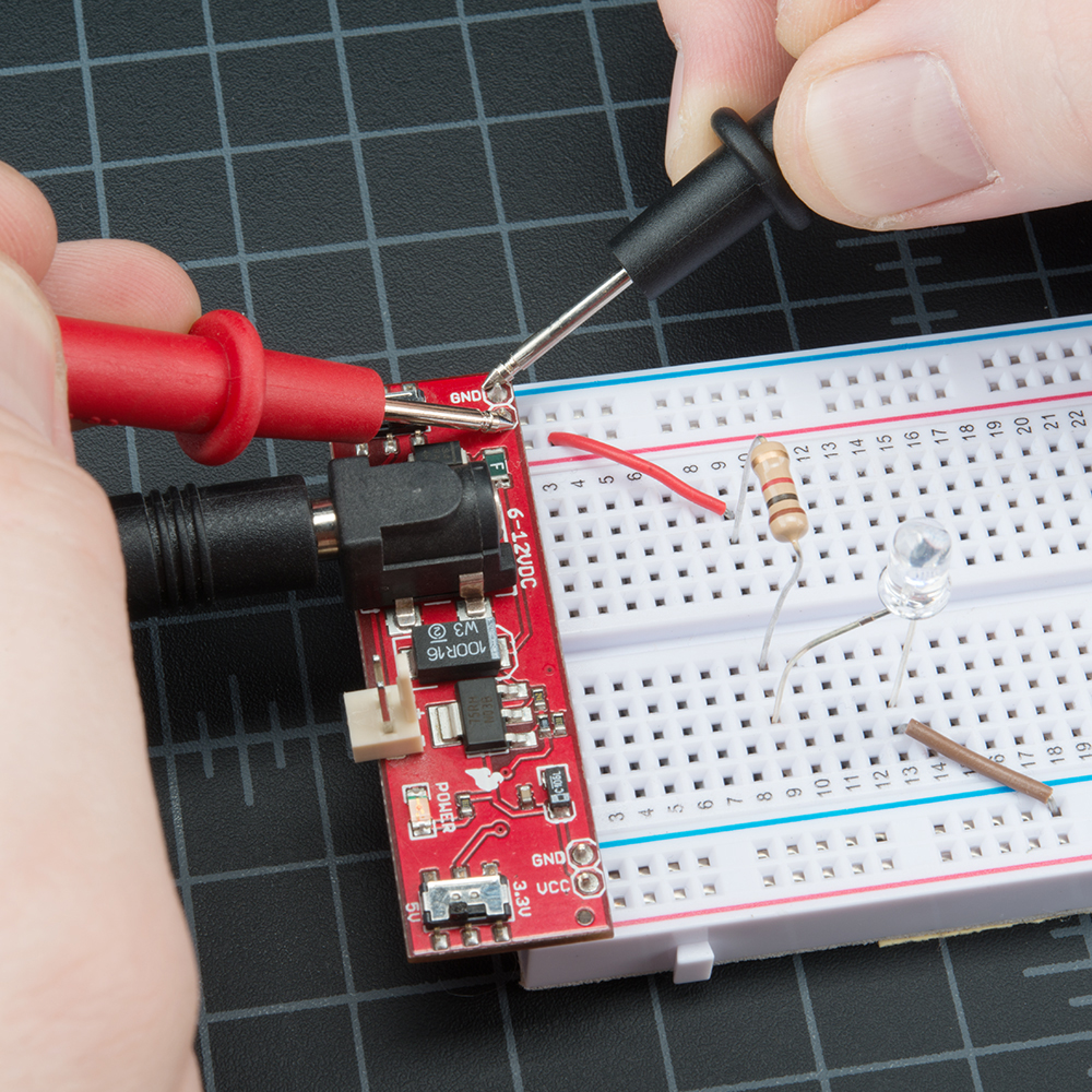
With some force (imagine poking a fork into a piece of cooked meat), push the probes onto two exposed pieces of metal. One probe should contact a GND connection. One probe to the VCC or 5V connection.
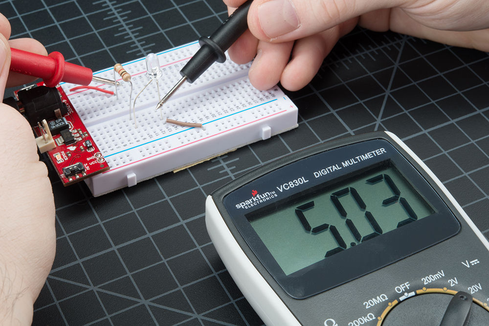
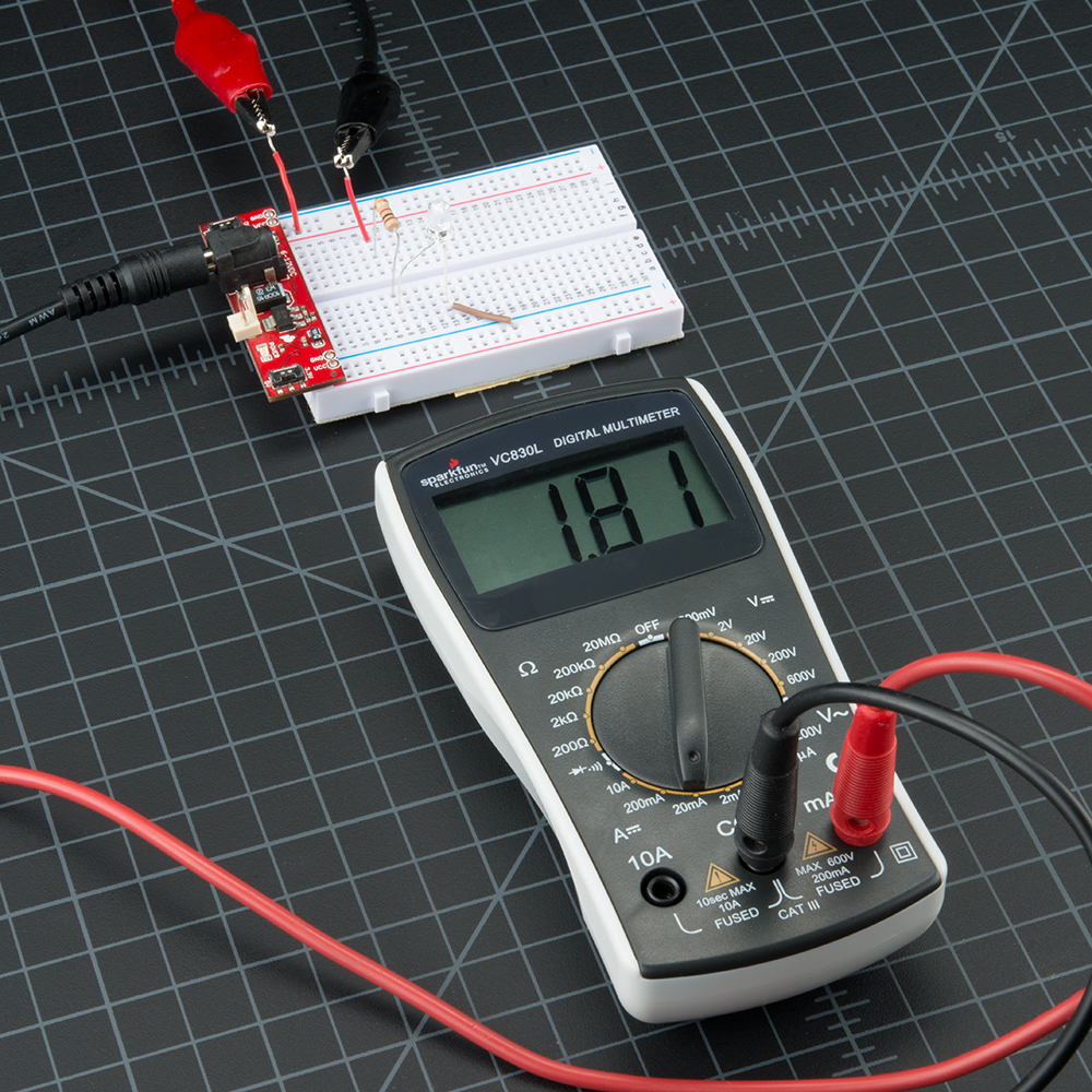
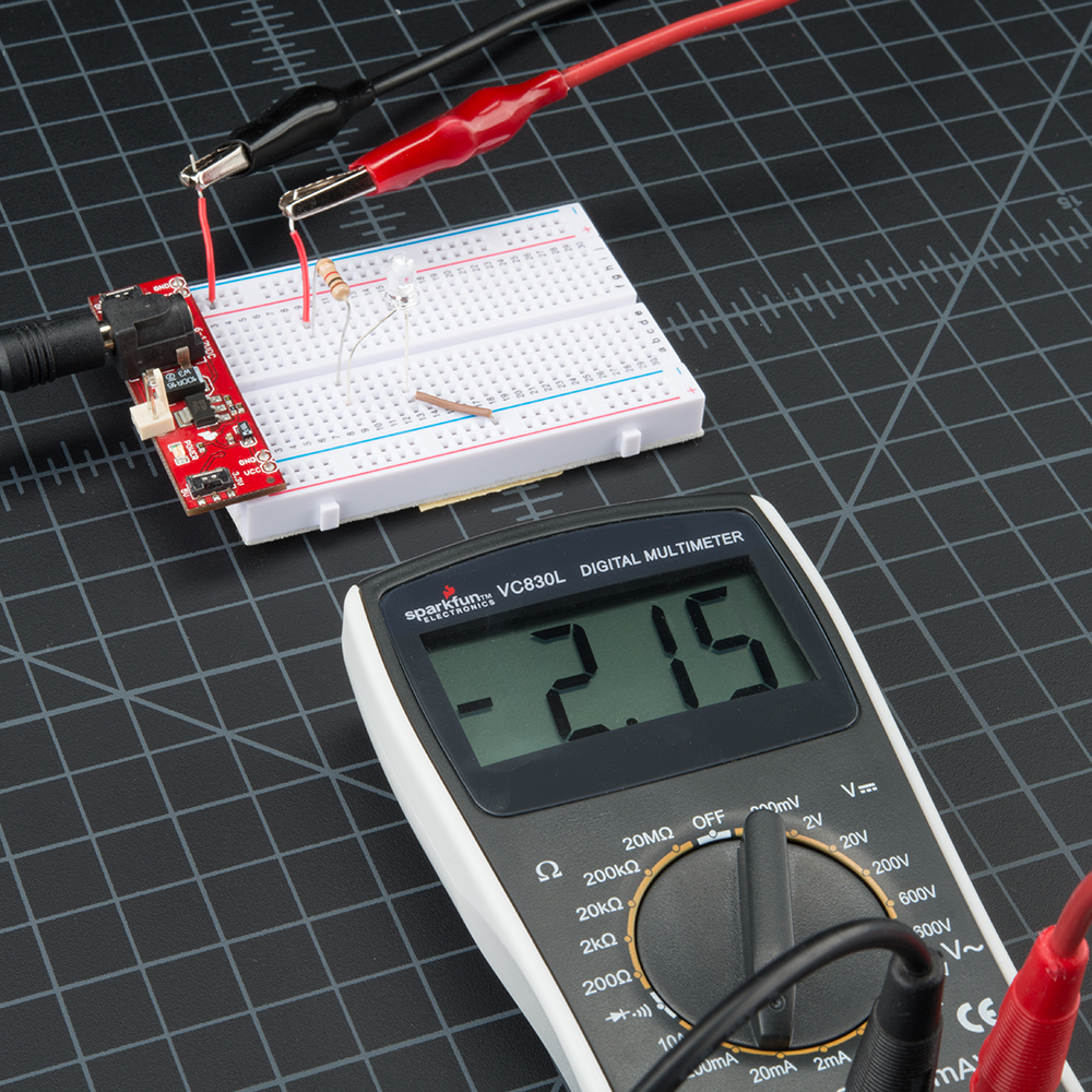
We can test different parts of the circuit as well. This practice is called nodal analysis, and it is a basic building block in circuit analysis. By measuring the voltage across the circuit we can see how much voltage each component requires. Let's measure the whole circuit first. Measuring from where the voltage is going in to the resistor and then where ground is on the LED, we should see the full voltage of the circuit, expected to be around 5V.
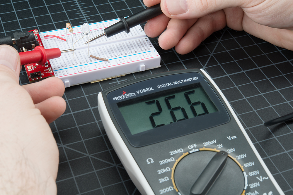
We can then see how much voltage the LED is using. This is what is referred to as the voltage drop across the LED. If that doesn't make sense now, fear not. It will as you explore the world of electronics more. The important thing to take away is that different parts of a circuit can be measured to analyze the circuit as a whole.
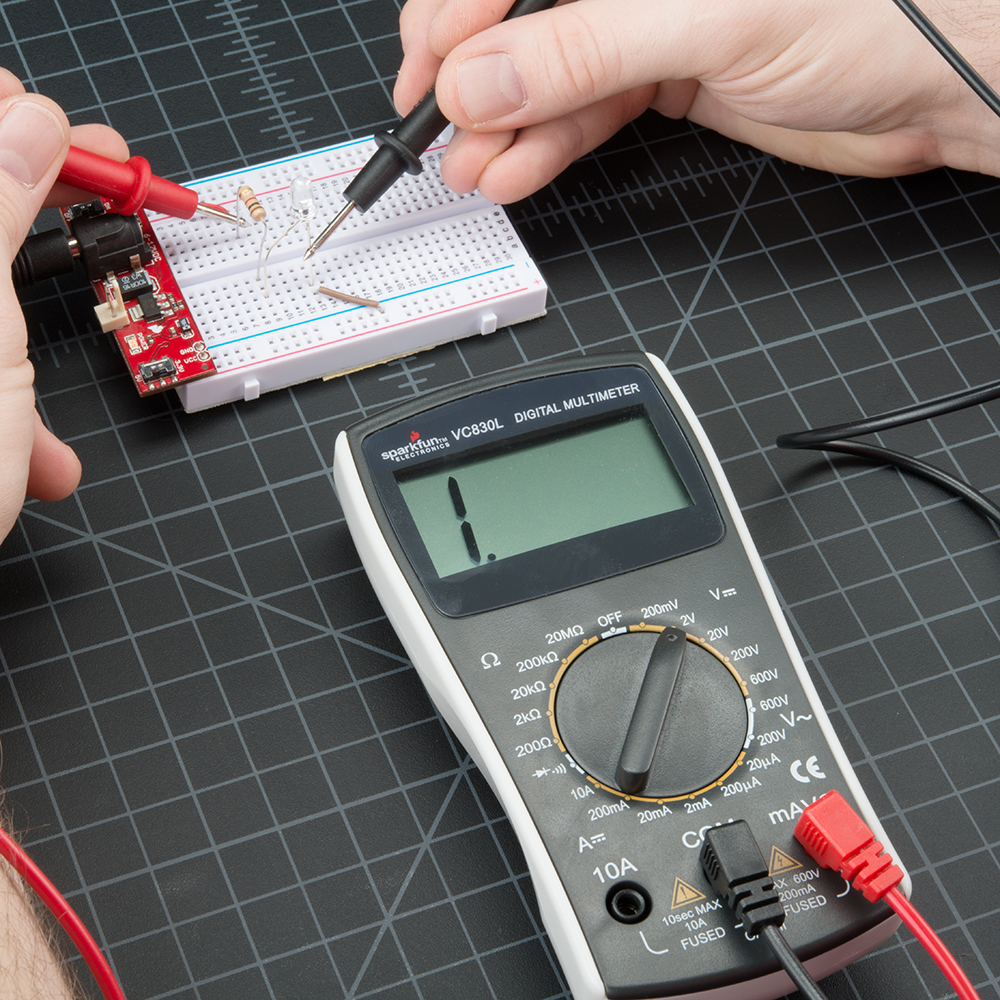
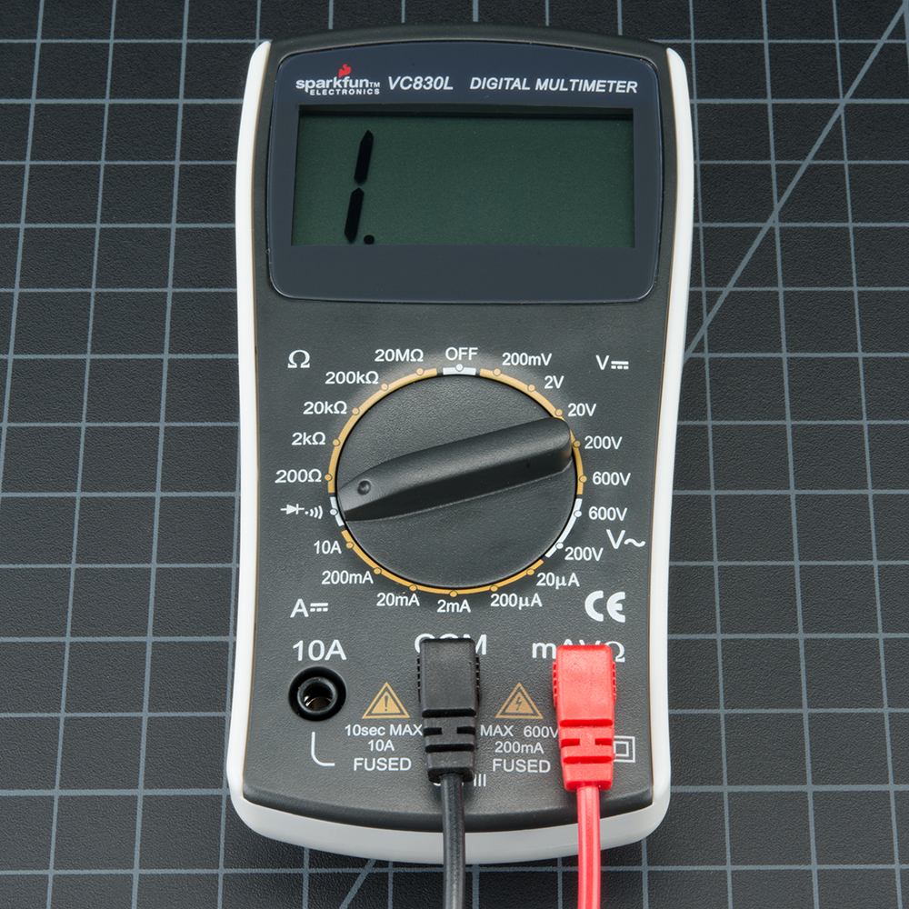
Overload
What happens if you select a voltage setting that is too low for the voltage you're trying to measure? Nothing bad. The meter will simply display a 1. This is the meter trying to tell you that it is overloaded or out-of-range. Whatever you're trying to read is too much for that particular setting. Try changing the multimeter knob to a the next highest setting.
Selection Knob
Why does the meter knob read 20V and not 10V? If you're looking to measure a voltage less than 20V, you turn to the 20V setting. This will allow you to read from 2.00 to 19.99.
The first digit on many multimeters is only able to display a '1' so the ranges are limited to 19.99 instead of 99.99. Hence the 20V max range instead of 99V max range.
Measuring Resistance
Normal resistors have color codes on them. If you don't know what they mean, that's ok! There are plenty of online calculators that are easy to use. However, if you ever find yourself without internet access, a multimeter is very handy at measuring resistance.
Pick out a random resistor and set the multimeter to the 20kΩ setting. Then hold the probes against the resistor legs with the same amount of pressure you when pressing a key on a keyboard.
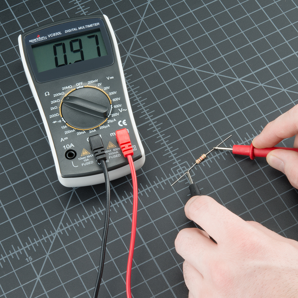
The meter will read one of three things, 0.00, 1, or the actual resistor value.
In this case, the meter reads 0.97, meaning this resistor has a value of 970Ω, or about 1kΩ (remember you are in the 20kΩ or 20,000 Ohm mode so you need to move the decimal three places to the right or 970 Ohms).
If the multimeter reads 1 or displays OL, it's overloaded. You will need to try a higher mode such as 200kΩ mode or 2MΩ (megaohm) mode. There is no harm if this happen, it simply means the range knob needs to be adjusted.
If the multimeter reads 0.00 or nearly zero, then you need to lower the mode to 2kΩ or 200Ω.
Remember that many resistors have a 5% tolerance. This means that the color codes may indicate 10,000 Ohms (10kΩ), but because of discrepancies in the manufacturing process a 10kΩ resistor could be as low as 9.5kΩ or as high as 10.5kΩ. Don't worry, it'll work just fine as a pull-up or general resistor.
Let's drop the meter down to the next lowest setting, 2KΩ. What happens?
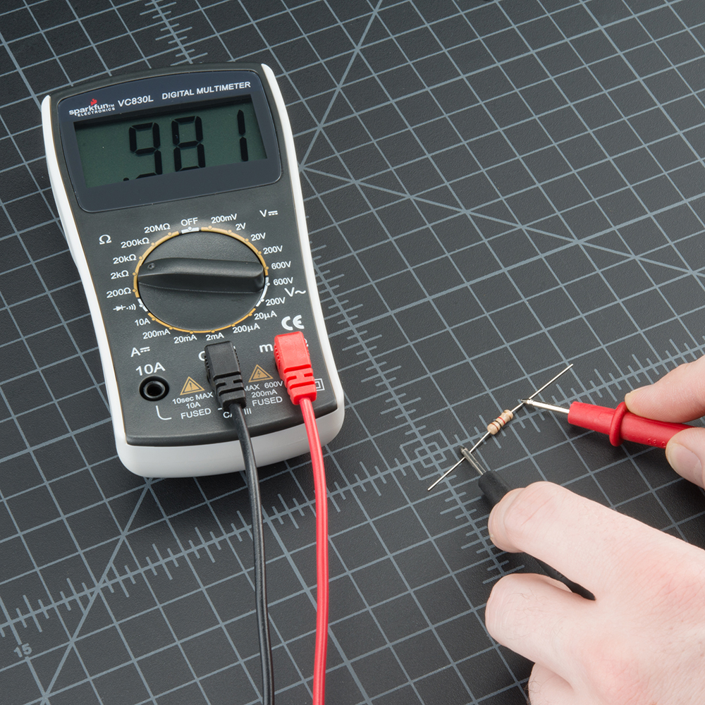
Not a whole lot changed. Because this resistor (a 1KΩ) is less than 2KΩ, it still shows up on the display. However, you'll notice that there is one more digit after the decimal point giving us a slightly higher resolution in our reading. What about the next lowest setting?
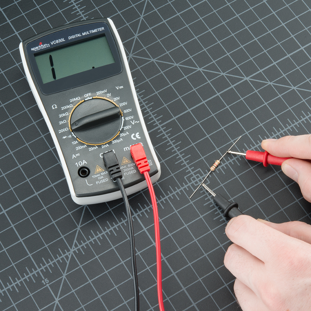
Now, since 1kΩ is greater than 200Ω, we've maxed out the meter, and it is telling you that it is overloaded and that you need to try a higher value setting.
As a rule of thumb, it's rare to see a resistor less than 1 Ohm. Remember that measuring resistance is not perfect. Temperature can affect the reading a lot. Also, measuring resistance of a device while it is physically installed in a circuit can be very tricky. The surrounding components on a circuit board can greatly affect the reading.
Measuring Current
Reading current is one of the trickiest and most insightful readings in the world of embedded electronics. It's tricky because you have to measure current in series. Where voltage is measure by poking at VCC and GND (in parallel), to measure current you have to physically interrupt the flow of current and put the meter in-line. To demonstrate this, we'll use the same circuit we used in the measuring voltage section.
The first thing we'll need is an extra piece of wire. As mentioned, we'll need to physically interrupt the circuit to measure the current. Said another way, pull out the VCC wire going to the resistor, add a wire where that wire was connected, and then probe from the power pin on the power supply to the resistor. This effectively "breaks" power to the circuit. We then insert the multimeter in-line so that it can measure the current as it "flows" through to the multimeter into the bread board.
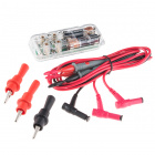
For these pictures, we cheated and used alligator clips. When measuring current, it's often good to watch what your system does over time, for a few seconds or minutes. While you might want to stand there and hold the probes to the system, sometimes it's easier to free up your hands. These alligator clip probes can come in handy. Note that almost all multimeters have the same sized jacks (they're called "banana plugs") so if you're in a pinch, you can use your friend's probes.
With the multimeter connected, we can now set the dial to the proper setting and measure some current. Measuring current works the same as voltage and resistance -- you have to get the correct range. Set the multimeter to 200mA, and work from there. The current consumption for many breadboard projects is usually under 200mA. Make sure the red probe is plugged into the 200mA fused port. On our favorite multimeter, the 200mA hole is the same port/hole as voltage and resistance reading (the port is labeled mAVΩ). This means you can keep the red probe in the same port to measure current, voltage, or resistance. However, if you suspect that your circuit will be using close to or more than 200mA, switch your probe to the 10A side, just to be safe. Overloading the current can result in a blown fuse rather than just an overload display. More on that in a bit.
Realize that the multimeter is acting as a piece of wire -- you've now completed the circuit, and the circuit will power on. This is important because as time goes on the LED, microcontroller, sensor, or whatever device being measured may change its power consumption (such as turning on an LED can resulting in a 20mA increase for a second, then decrease for a second when it turns off). On the multimeter display you should see the instantaneous current reading. All multimeters take readings over time and then give you the average, so expect the reading to fluctuate. In general, cheaper meters will average more harshly and respond more slowly, so take each reading with a grain of salt. In your head, take an average range such as 7 to 8mA under normal 5V conditions (not 7.48mA).
Similar to the other measurements, when measuring current, the color of the probes does not matter. What happens if we switch probes? Nothing bad happens! It simply causes the current reading to become negative:
Current is still flowing through the system, you've just changed your perspective and now the meter reads negative.
Measuring current can be tricky the first couple of times. Don't worry if you blow the fuse - we've done it dozens of times! We'll show you how to replace the fuse in a later section.
Continuity
Continuity testing is the act of testing the resistance between two points. If there is very low resistance (less than a few Ωs), the two points are connected electrically, and a tone is emitted. If there is more than a few Ωs of resistance, than the circuit is open, and no tone is emitted. This test helps insure that connections are made correctly between two points. This test also helps us detect if two points are connected that should not be.
Continuity is quite possibly the single most important function for embedded hardware gurus. This feature allows us to test for conductivity of materials and to trace where electrical connections have been made or not made.
Set the multimeter to 'Continuity' mode. It may vary among DMMs, but look for a diode symbol with propagation waves around it (like sound coming from a speaker).
Now touch the probes together. The multimeter should emit a tone (Note: Not all multimeters have a continuity setting, but most should). This shows that a very small amount of current is allowed to flow without resistance (or at least a very very small resistance) between probes.
On a breadboard that is not powered, use the probes to poke at two separate ground pins. You should hear a tone indicating that they are connected. Poke the probes from the VCC pin on a microcontroller to VCC on your power supply. It should emit a tone indicating that power is free to flow from the VCC pin to the micro. If it does not emit a tone, then you can begin to follow the route that copper trace takes and tell if there are breaks in the line, wire, breadboard, or PCB.
Continuity is a great way to test if two SMD pins are touching. If your eyes can't see it, the multimeter is usually a great second testing resource.
When a system is not working, continuity is one more thing to help troubleshoot the system. Here are the steps to take:
- If the system is on, carefully check VCC and GND with the voltage setting to make sure the voltage is the correct level. If the 5V system is running at 4.2V check your regulator carefully, it could be very hot indicating the system is pulling too much current.
- Power the system down and check continuity between VCC and GND. If there is continuity (if you hear a beep), then you've got a short somewhere.
- Power the system down. With continuity, check that VCC and GND are correctly wired to the pins on the microcontroller and other devices. The system may be powering up, but the individual ICs may be wired wrong.
- Assuming you can get the microcontroller running, set the multimeter aside, and move on to serial debugging or use a logic analyzer to inspect the digital signals.
Continuity and large capacitors: During normal troubleshooting. you will be probing for continuity between ground and the VCC rail. This is a good sanity check before powering up a prototype to make sure there is not a short on the power system. But don't be surprised if you hear a short 'beep!' when probing. This is because there is often significant amounts of capacitance on the power system. The multimeter is looking for very low resistance to see if two points are connected. Capacitors will act like a short for a split second until they fill up with energy, and then act like an open connection. Therefore, you will hear a short beep and then nothing. That's ok, it's just the caps charging up.
Changing the Fuse
One of the most common mistakes with a new multimeter is to measure current on a bread board by probing from VCC to GND (bad!). This will immediately short power to ground through the multimeter causing the bread board power supply to brown out. As the current rushes through the multimeter, the internal fuse will heat up and then burn out as 200mA flows through it. It will happen in a split second and without any real audible or physical indication that something is wrong.
Wow, that was neat. Now what? Well first, remember that measuring current is done in series (interrupt the VCC line to the breadboard or microcontroller to measure current). If you try to measure the current with a blown fuse, you'll probably notice that the meter reads '0.00' and that the system doesn't turn on like it should when you attach the multimeter. This is because the internal fuse is broken and acts as a broken wire or open. Don't worry, this happens all the time, and it costs about $1 to fix.
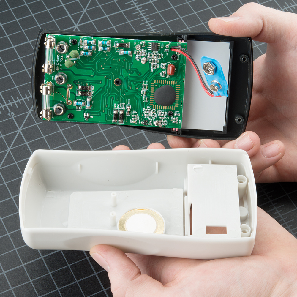
To change the fuse, find your handy dandy mini screw driver, and start taking out screws. The SparkFun DMM is pretty easy to pull apart. Start by removing the battery plate and the battery.
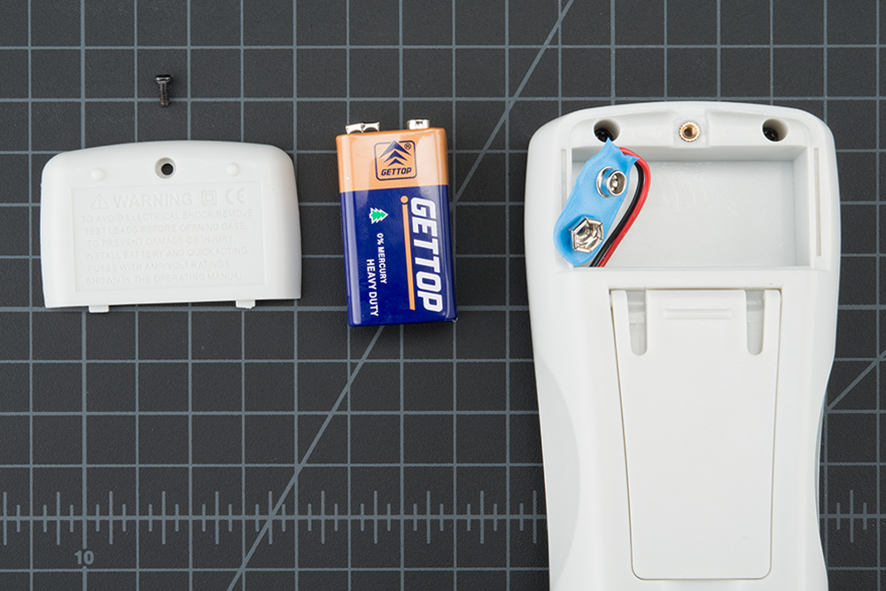
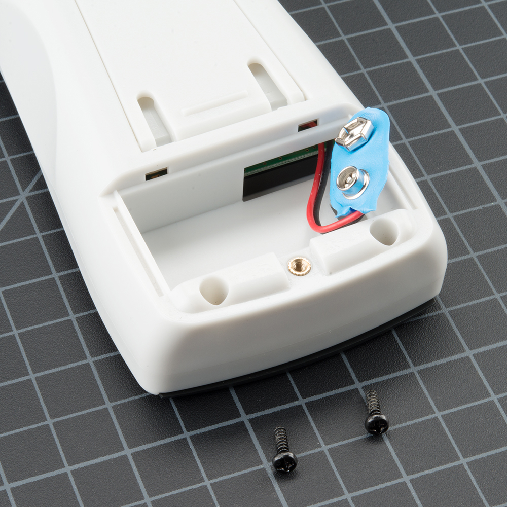
Next, remove the two screws hiding behind the battery plate.
Lift the face of the multimeter slightly.
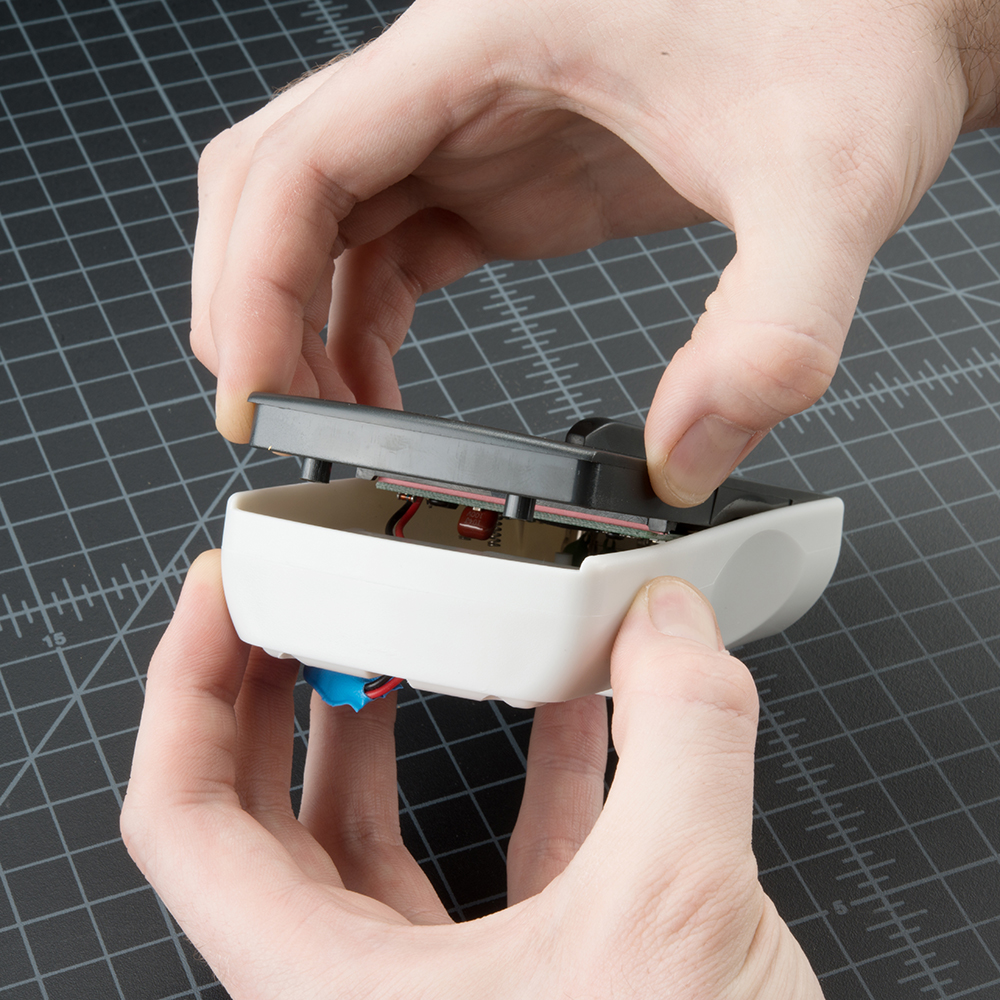
Now notice the hooks on the bottom edge of the face. You will need to slide the face sideways with a little force to disengage these hooks.
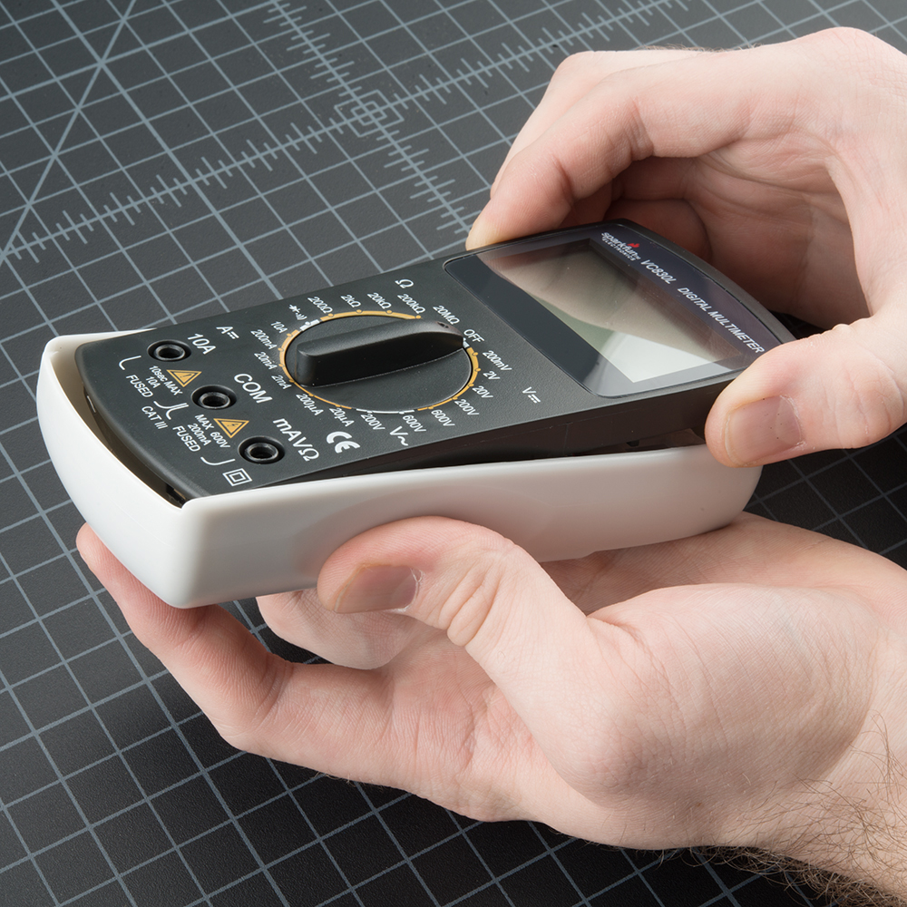
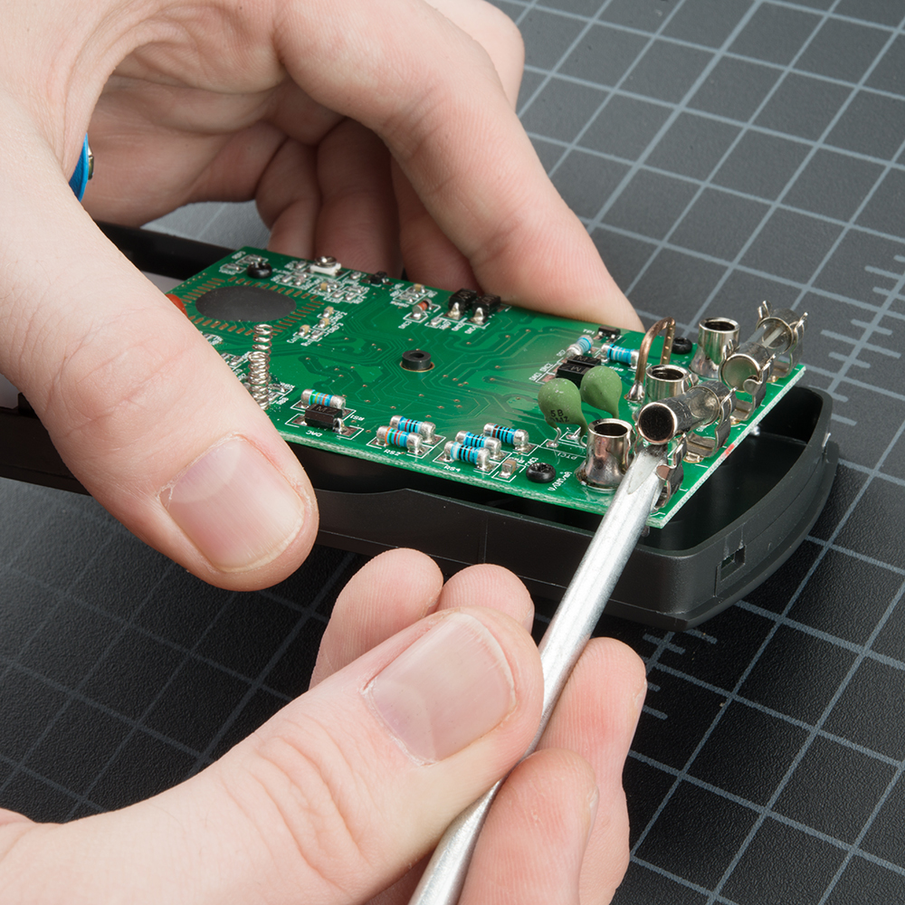
Once the face is unhooked, it should come out easily. Now you can see inside the multimeter!
Gently lift up on the fuse, and it will pop out.
Make sure to replace the correct fuse with the correct type. In other words, replace the 200mA fuse with a 200mA fuse.
The components and PCB traces inside the multimeter are designed to take different amounts of current. You will damage and possibly ruin your multimeter if you accidentally push 5A through the 200mA port.
There are times where you need to measure high current devices like a motor or heating element. Do you see the two places to put the red probe on the front of the multimeter? 10A on the left and mAVΩ on the right? If you try to measure more than 200mA on the mAVΩ port you run the risk of blowing the fuse. But if you use the 10A port to measure current, you run a much lower risk of blowing the fuse. The trade-off is sensitivity. As we talked about above, by using the 10A port and knob setting, you will only be able to read down to 0.01A or 10mA. Most of my systems use more than 10mA so the 10A setting and port works well enough. If you're trying to measure very low power (micro or nano amps) the 200mA port with the 2mA, 200uA, or 20uA could be what you need.
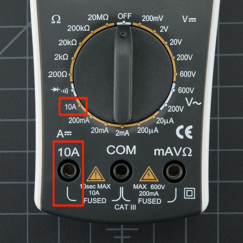
Remember: If your system has the potential to use more than 100mA you should start with the red probe plugged into the 10A port and 10A knob setting.
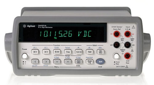
With sub $50 digital multimeters, the measurements you are likely to take are just trouble shooting readings, not scientific experimental results. If you really need to see how the IC uses current or voltage over time, use an Agilent or other high quality bench unit. These units have higher precision and offer a wide range of fancy functions (some include Tetris!). Bunnie Huang, hardware designer behind Chumby, uses high-precision current readings to trouble shoot boards during the final testing procedures of a Chumby. By looking at the current consumption of different boards that have failed (for example a given failed board uses 210mA over the normal), he could identify what was wrong with the board (when the RAM fails, it generally uses 210mA over normal). By pinpointing what may be potentially wrong, the rework and repair of boards is made much easier.
What Makes a Good Multimeter?
Everyone has his or her preference, but in general multimeters that have continuity are preferred. Every other feature is just icing on the cake.
There are fancy multimeters that are autoranging, meaning they automatically change their internal range to attempt to find the correct voltage, resistance, or current of the thing you're poking at. Auto-ranging can be very helpful if you know how to use it. Generally speaking, autoranging multimeters are higher quality and generally have more features. So if someone gives you a multimeter with auto-range, put it to use! Just know how to get it into manual mode. A circuit's voltage or current can fluctuate quite quickly. With some of the systems, the current or voltage is so sporadic that the auto-range can't keep up sensibly.
A back-lit LCD is fancy, but when was the last time you measured your circuit in the dark? We generally steer clear of scary forests and situations that require us to test stuff in the middle of the night, but some people may want or need a dark-friendly multimeter.
A good click on the range selector is actually a major plus in our book. A soft knob is usually indicative of a shoddy meter.
Decent probes are a plus. Over time the leads will tend to break down at the flex point. We've seen wires come completely out of probes - and it's always at the moment you need the probes to work! If you do break a probe, they are reasonably cheap to replace.
Auto-off is a great feature that is rarely seen on cheaper multimeters. This is a feature that can benefit beginners and advanced users alike, as it's easy to forget to turn the meter off at 2AM. The SparkFun digital multimeter doesn't have this feature, but luckily the meter is very low-power. We've left the multimeter for two days straight before the 9V battery began to get low. That said, don't forget to turn your meter off!
You're now ready to use your digital multimeter to start measuring the world around you. Feel free to start using it to answer many questions. I believe my LED is getting 20mA, is it really? How much voltage does a lemon have? Is a glass of water conductive? Can I use aluminum foil to replace these wires? A digital multimeter will answer these and many more questions about electronics.
Purchasing a Multimeter
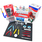
A digital multimeter is an essential tool in every electronic enthusiasts arsenal. Here are a few multimeters and kits with multimeters to suit the needs of beginners and experienced hobbyists alike.
Our Recommendations:
Interested in learning more foundational topics?
See our Engineering Essentials page for a full list of cornerstone topics surrounding electrical engineering.

Resources and Going Further
Now that you know the basics of how to use a digital multimeter, check out these tutorials to use your new skill:
- Testing LED and Diode Polarity with a Multimeter
- LEDs
- Diodes
- Electric Power
- Battery Technologies
- Powering Your Project
Or check out some of these related blog posts.