Series and Parallel Circuits
 Pete-O
 Series and Parallel Circuits
Simple circuits (ones with only a few components) are usually fairly straightforward for beginners to understand. But, things can get sticky when other components come to the party. Where's the current going? What's the voltage doing? Can this be simplified for easier understanding? Fear not, intrepid reader. Valuable information follows.
In this tutorial, we’ll first discuss the difference between series circuits and parallel circuits, using circuits containing the most basic of components -- resistors and batteries -- to show the difference between the two configurations. We’ll then explore what happens in series and parallel circuits when you combine different types of components, such as capacitors and inductors.
Covered in this Tutorial
- What series and parallel circuit configurations look like
- How passive components act in these configurations
- How a voltage source will act upon passive components in these configurations
Suggested Reading
You may want to visit these tutorials on the basic components before diving into building the circuits in this tutorial.
- What is Electricity
- Voltage, Current, Resistance, and Ohm's Law
- What is a Circuit?
- Capacitors
- Inductors
- Resistors
- How to Use a Breadboard
- How to Use a Multimeter
Video
Series Circuits
Nodes and Current Flow
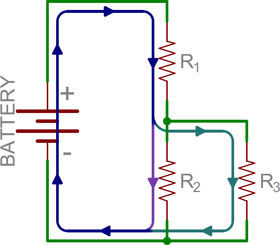
Before we get too deep into this, we need to mention what a node is. It's nothing fancy, just representation of an electrical junction between two or more components. When a circuit is modeled on a schematic, these nodes represent the wires between components.
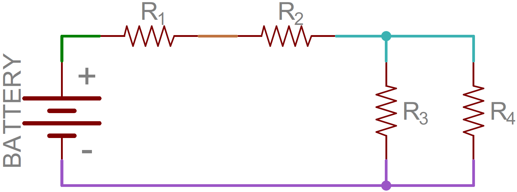
That's half the battle towards understanding the difference between series and parallel. We also need to understand how current flows through a circuit. Current flows from a high voltage to a lower voltage in a circuit. Some amount of current will flow through every path it can take to get to the point of lowest voltage (usually called ground). Using the above circuit as an example, here's how current would flow as it runs from the battery's positive terminal to the negative:
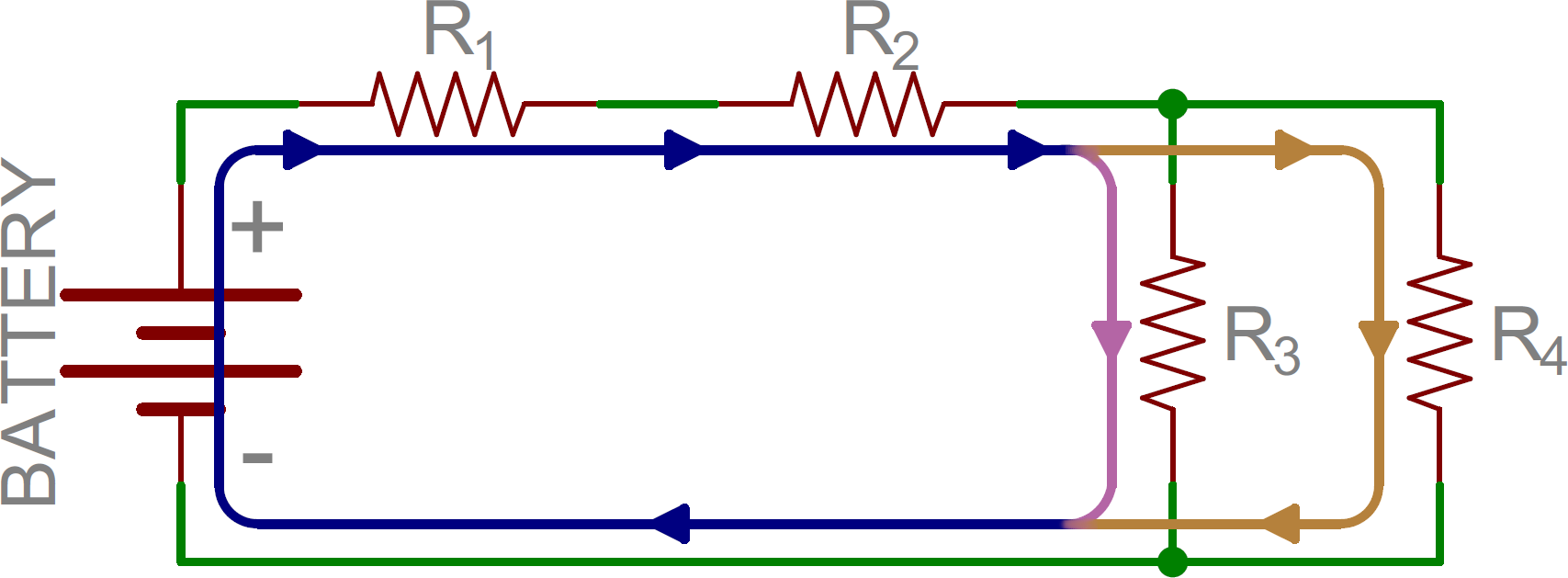
Notice that in some nodes (like between R1 and R2) the current is the same going in as at is coming out. At other nodes (specifically the three-way junction between R2, R3, and R4) the main (blue) current splits into two different ones. That's the key difference between series and parallel!
Series Circuits Defined
Two components are in series if they share a common node and if the same current flows through them. Here's an example circuit with three series resistors:
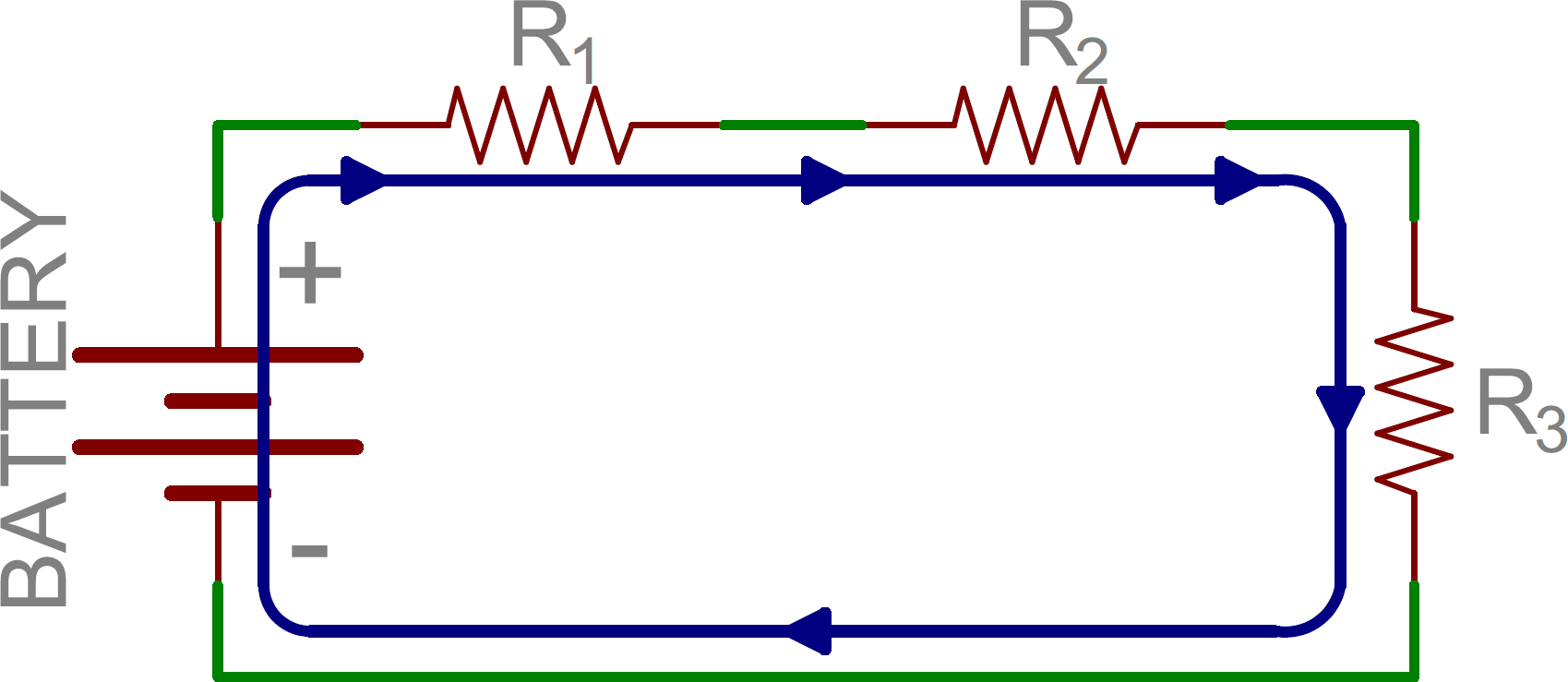
There's only one way for the current to flow in the above circuit. Starting from the positive terminal of the battery, current flow will first encounter R1. From there the current will flow straight to R2, then to R3, and finally back to the negative terminal of the battery. Note that there is only one path for current to follow. These components are in series.
Parallel Circuits
Parallel Circuits Defined
If components share two common nodes, they are in parallel. Here's an example schematic of three resistors in parallel with a battery:
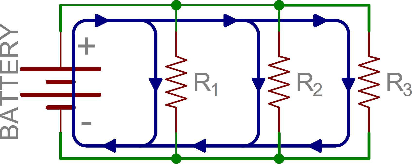
From the positive battery terminal, current flows to R1... and R2, and R3. The node that connects the battery to R1 is also connected to the other resistors. The other ends of these resistors are similarly tied together, and then tied back to the negative terminal of the battery. There are three distinct paths that current can take before returning to the battery, and the associated resistors are said to be in parallel.
Where series components all have equal currents running through them, parallel components all have the same voltage drop across them -- series:current::parallel:voltage.
Series and Parallel Circuits Working Together
From there we can mix and match. In the next picture, we again see three resistors and a battery. From the positive battery terminal, current first encounters R1. But, at the other side of R1 the node splits, and current can go to both R2 and R3. The current paths through R2 and R3 are then tied together again, and current goes back to the negative terminal of the battery.
In this example, R2 and R3 are in parallel with each other, and R1 is in series with the parallel combination of R2 and R3.
Calculating Equivalent Resistances in Series Circuits
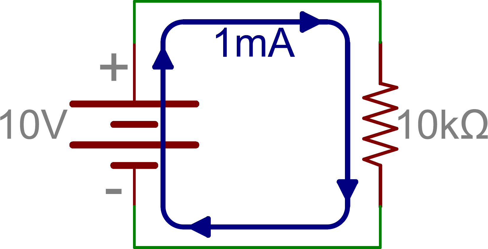
Here’s some information that may be of some more practical use to you. When we put resistors together like this, in series and parallel, we change the way current flows through them. For example, if we have a 10V supply across a 10kΩ resistor, Ohm’s law says we've got 1mA of current flowing.
If we then put another 10kΩ resistor in series with the first and leave the supply unchanged, we've cut the current in half because the resistance is doubled.
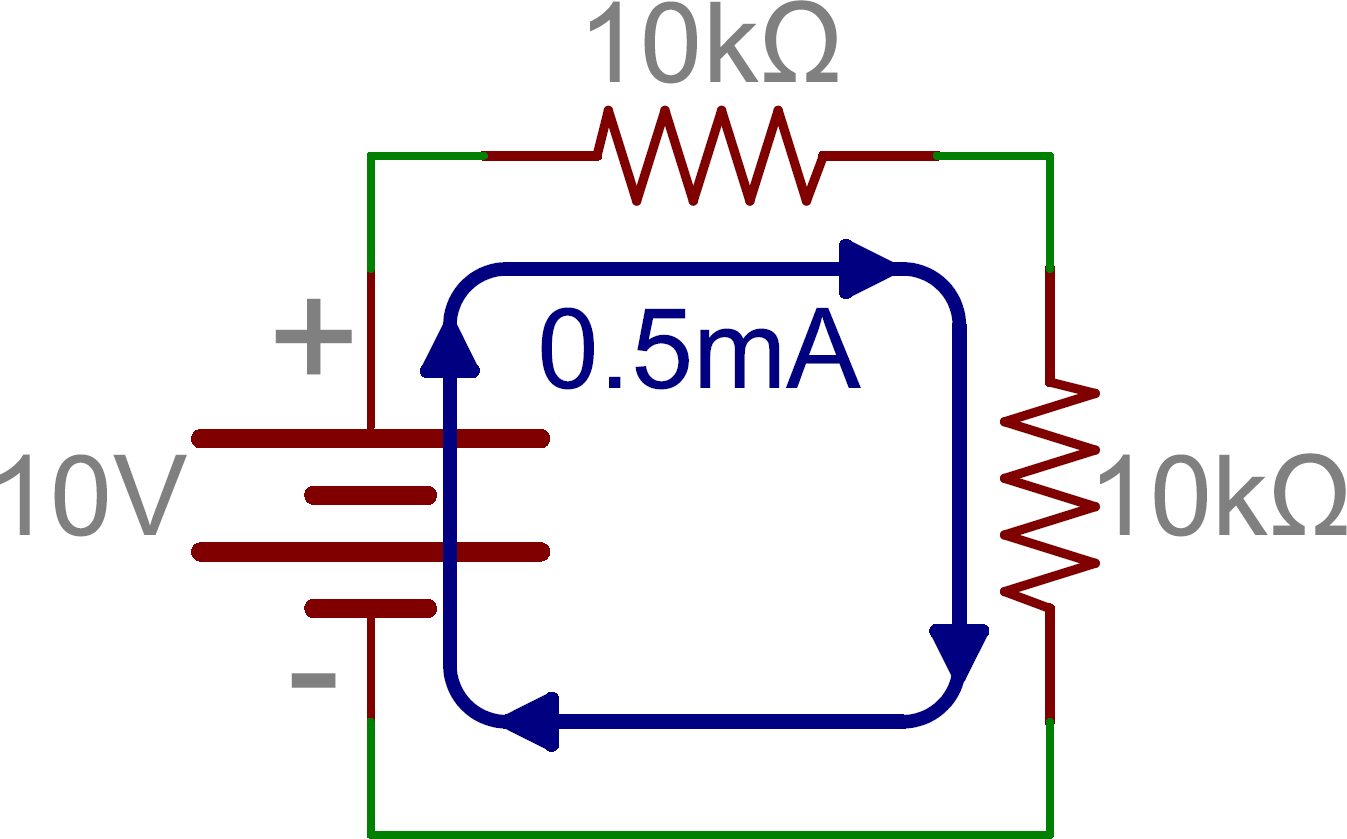
In other words, there's still only one path for current to take and we just made it even harder for current to flow. How much harder? 10kΩ + 10kΩ = 20kΩ. And, that’s how we calculate resistors in series -- just add their values.
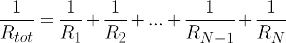
To put this equation more generally: the total resistance of N -- some arbitrary number of -- resistors is their total sum.


Calculating Equivalent Resistances in Parallel Circuits
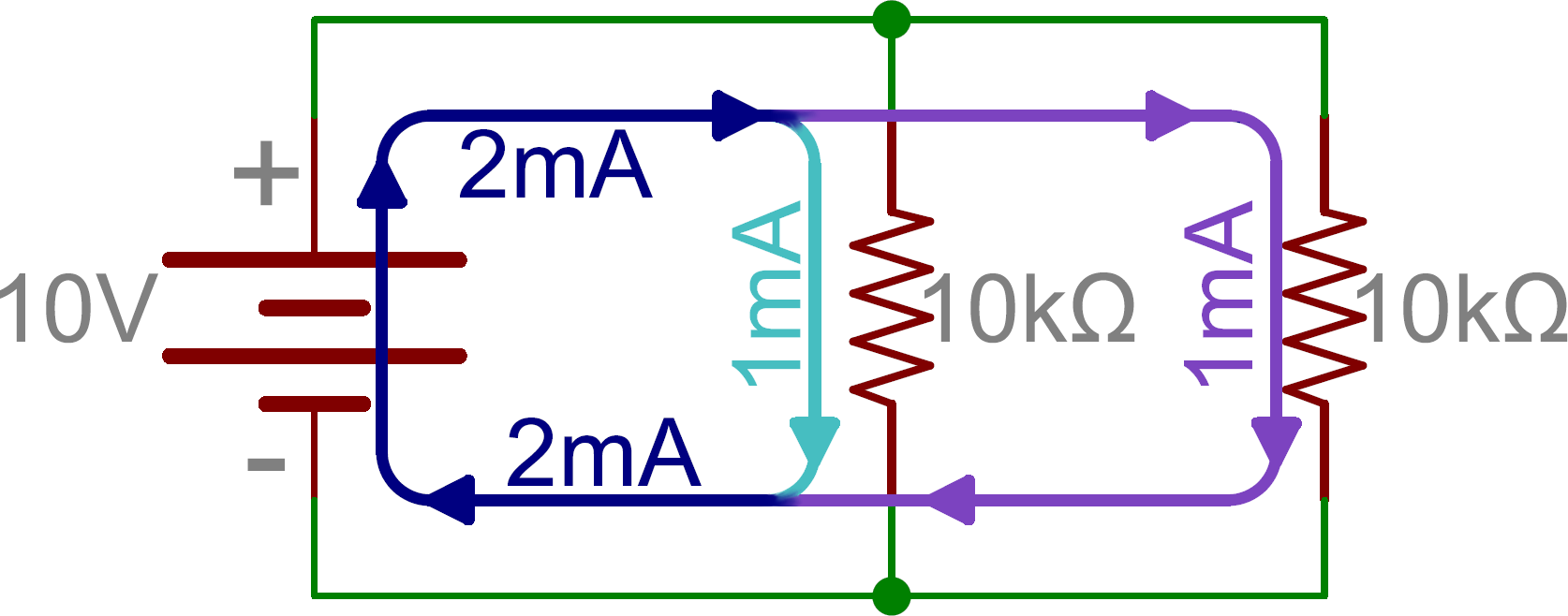
What about parallel resistors? That’s a bit more complicated, but not by much. Consider the last example where we started with a 10V supply and a 10kΩ resistor, but this time we add another 10kΩ in parallel instead of series. Now there are two paths for current to take. Since the supply voltage didn’t change, Ohm’s Law says the first resistor is still going to draw 1mA. But, so is the second resistor, and we now have a total of 2mA coming from the supply, doubling the original 1mA. This implies that we’ve cut the total resistance in half.
While we can say that 10kΩ || 10kΩ = 5kΩ (“||” roughly translates to “in parallel with”), we’re not always going to have 2 identical resistors. What then?
The equation for adding an arbitrary number of resistors in parallel is:
If reciprocals aren't your thing, we can also use a method called “product over sum” when we have two resistors in parallel:
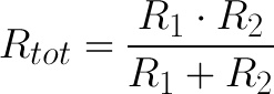
However, this method is only good for two resistors in one calculation. We can combine more than 2 resistors with this method by taking the result of R1 || R2 and calculating that value in parallel with a third resistor (again as product over sum), but the reciprocal method may be less work.
Experiment Time - Part 1
What you’ll need:
Let’s try a simple experiment just to prove that these things work the way we're saying they do.
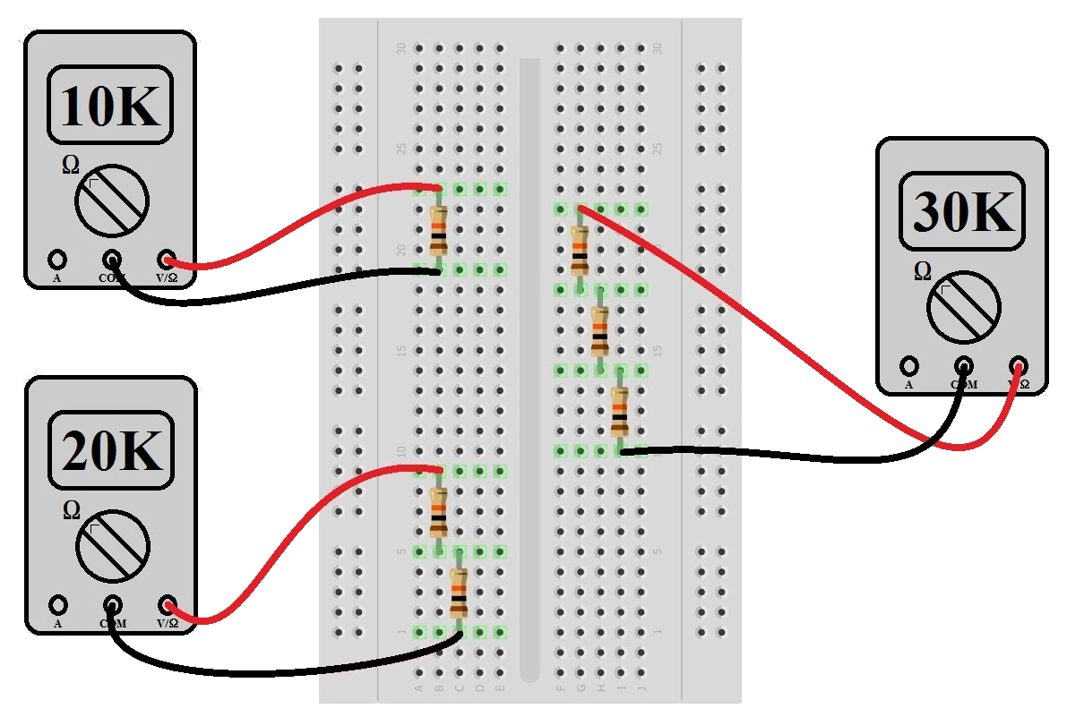
First, we’re going to hook up some 10kΩ resistors in series and watch them add in a most un-mysterious way. Using a breadboard, place one 10kΩ resistor as indicated in the figure and measure with a multimeter. Yes, we already know it’s going to say it’s 10kΩ, but this is what we in the biz call a “sanity check”. Once we’ve convinced ourselves that the world hasn't changed significantly since we last looked at it, place another one in similar fashion but with a lead from each resistor connecting electrically through the breadboard and measure again. The meter should now say something close to 20kΩ.
You may notice that the resistance you measure might not be exactly what the resistor says it should be. Resistors have a certain amount of tolerance, which means they can be off by a certain percentage in either direction. Thus, you may read 9.99kΩ or 10.01kΩ. As long as it's close to the correct value, everything should work fine.
The reader should continue this exercise until convincing themselves that they know what the outcome will be before doing it again, or they run out of resistors to stick in the breadboard, whichever comes first.
Experiment Time - Part 2
Now let’s try it with resistors in a parallel configuration. Place one 10kΩ resistor in the breadboard as before (we’ll trust that the reader already believes that a single 10kΩ resistor is going to measure something close to 10kΩ on the multimeter). Now place a second 10kΩ resistor next to the first, taking care that the leads of each resistor are in electrically connected rows. But before measuring the combination, calculate by either product-over-sum or reciprocal methods what the new value should be (hint: it’s going to be 5kΩ). Then measure. Is it something close to 5kΩ? If it’s not, double check the holes into which the resistors are plugged.
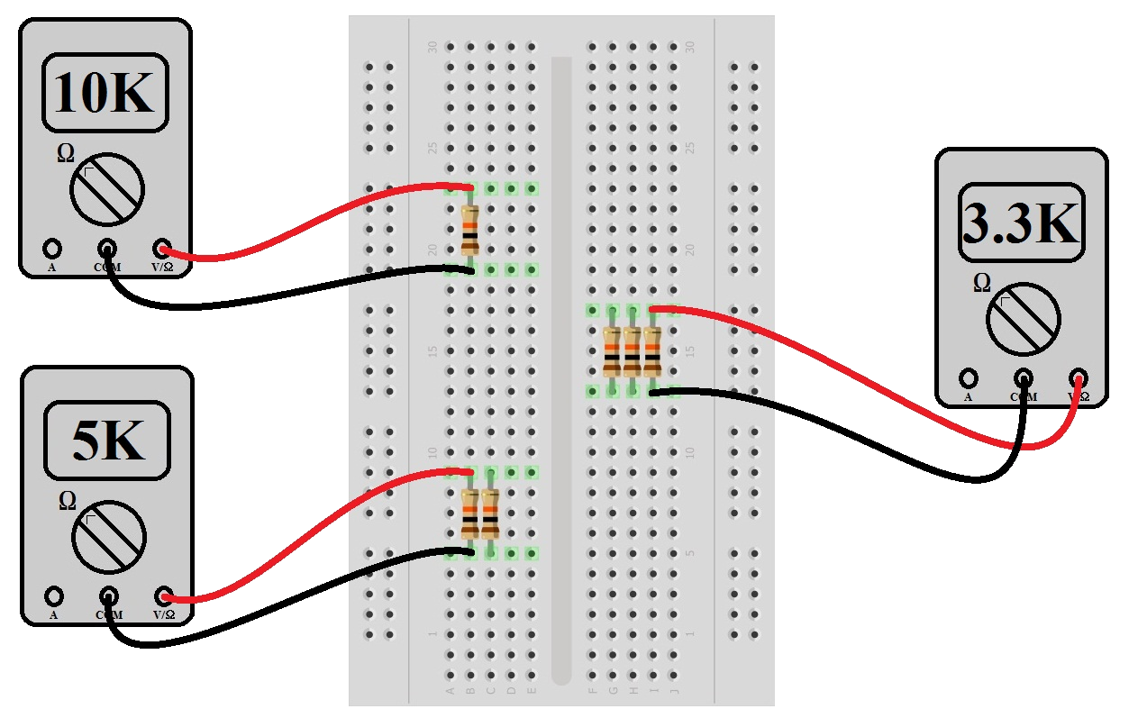
Repeat the exercise now with 3, 4 and 5 resistors. The calculated/measured values should be 3.33kΩ, 2.5kΩ and 2kΩ, respectively. Did everything come out as planned? If not, go back and check your connections. If it did, EXCELSIOR! Go have a milkshake before we continue. You’ve earned it.
Rules of Thumb for Series and Parallel Resistors
There are a few situations that may call for some creative resistor combinations. For example, if we’re trying to set up a very specific reference voltage you’ll almost always need a very specific ratio of resistors whose values are unlikely to be “standard” values. And while we can get a very high degree of precision in resistor values, we may not want to wait the X number of days it takes to ship something, or pay the price for non-stocked, non-standard values. So in a pinch, we can always build our own resistor values.
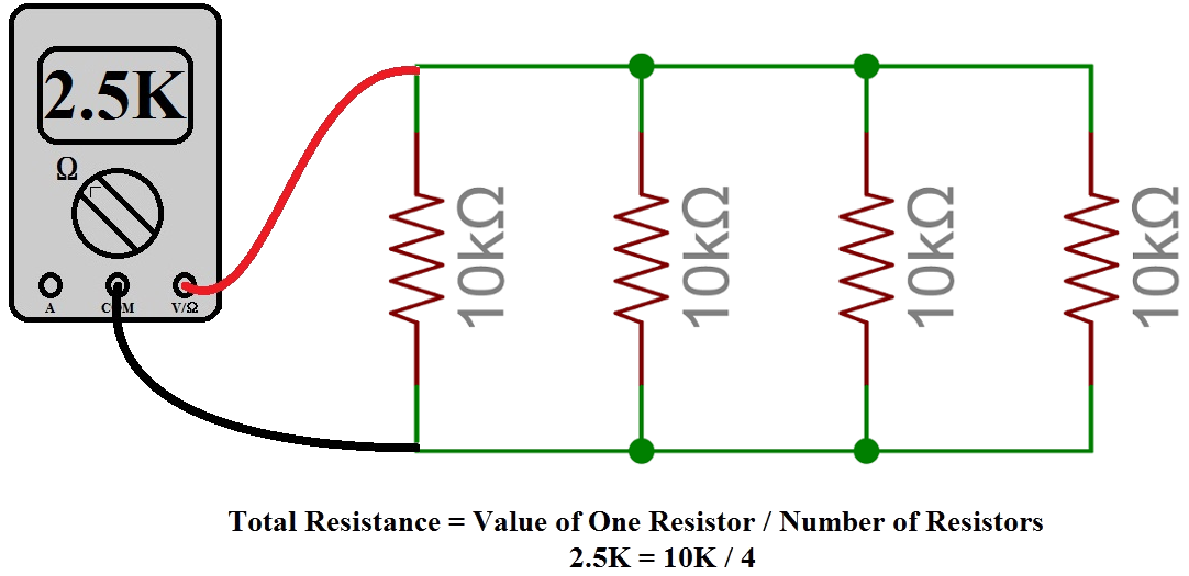
Tip #1: Equal Resistors in Parallel
Adding N like-valued resistors R in parallel gives us R/N ohms. Let’s say we need a 2.5kΩ resistor, but all we’ve got is a drawer full of 10kΩ's. Combining four of them in parallel gives us 10kΩ/4 = 2.5kΩ.
Tip #2: Tolerance
Know what kind of tolerance you can tolerate. For example, if you needed a 3.2kΩ resistor, you could put 3 10kΩ resistors in parallel. That would give you 3.3kΩ, which is about a 4% tolerance from the value you need. But, if the circuit you're building needs to be closer than 4% tolerance, we can measure our stash of 10kΩ’s to see which are lowest values because they have a tolerance, too. In theory, if the stash of 10kΩ resistors are all 1% tolerance, we can only get to 3.3kΩ. But part manufacturers are known to make just these sorts of mistakes, so it pays to poke around a bit.
Tip #3: Power Ratings in Series/Parallel
This sort of series and parallel combination of resistors works for power ratings, too. Let’s say that we need a 100Ω resistor rated for 2 watts (W), but all we’ve got is a bunch of 1kΩ quarter-watt (¼W) resistors (and it’s 3am, all the Mountain Dew is gone, and the coffee’s cold). You can combine 10 of the 1kΩ's to get 100Ω (1kΩ/10 = 100Ω), and the power rating will be 10x0.25W, or 2.5W. Not pretty, but it will get us through a final project, and might even get us extra points for being able to think on our feet.
We need to be a little more careful when we combine resistors of dissimilar values in parallel where total equivalent resistance and power ratings are concerned. It should be completely obvious to the reader, but...
Tip #4: Different Resistors in Parallel
The combined resistance of two resistors of different values is always less than the smallest value resistor. The reader would be amazed at how many times someone combines values in their head and arrives at a value that’s halfway between the two resistors (1kΩ || 10kΩ does NOT equal anything around 5kΩ!). The total parallel resistance will always be dragged closer to the lowest value resistor. Do yourself a favor and read tip #4 10 times over.
Tip #5: Power Dissipation in Parallel
The power dissipated in a parallel combination of dissimilar resistor values is not split evenly between the resistors because the currents are not equal. Using the previous example of (1kΩ || 10kΩ), we can see that the 1kΩ will be drawing 10X the current of the 10kΩ. Since Ohm’s Law says power = voltage x current, it follows that the 1kΩ resistor will dissipate 10X the power of the 10kΩ.
Ultimately, the lessons of tips 4 and 5 are that we have to pay closer attention to what we’re doing when combining resistors of dissimilar values in parallel. But tips 1 and 3 offer some handy shortcuts when the values are the same.
Series and Parallel Capacitors
Combining capacitors is just like combining resistors...only the opposite. As odd as that sounds, it’s absolutely true. Why would this be?
A capacitor is just two plates spaced very close together, and it’s basic function is to hold a whole bunch of electrons. The greater the value of capacitance, the more electrons it can hold. If the size of the plates is increased, the capacitance goes up because there's physically more space for electrons to hang out. And if the plates are moved farther apart, the capacitance goes down, because the electric field strength between them goes down as the distance goes up.
Now let’s say we've got two 10µF capacitors wired together in series, and let’s say they’re both charged up and ready discharge into the friend sitting next to you.
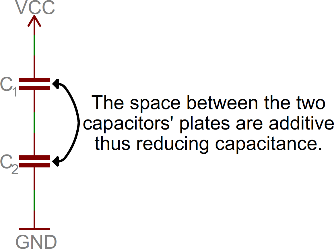
Remember that in a series circuit there's only one path for current to flow. It follows that the number of electrons that are discharging from the cap on the bottom is going to be the same number of electrons coming out of the cap on the top. So the capacitance hasn't increased, has it?
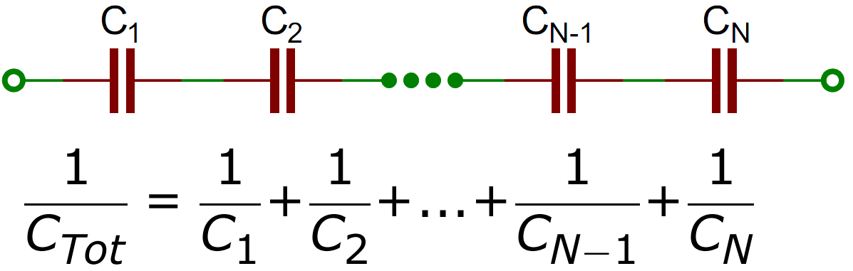
In fact, it’s even worse than that. By placing the capacitors in series, we've effectively spaced the plates farther apart because the spacing between the plates of the two capacitors adds together. So we don't have 20µF, or even 10µF. We’ve got 5µF. The upshot of this is that we add series capacitor values the same way we add parallel resistor values. Both the product-over-sum and reciprocal methods are valid for adding capacitors in series.
It may seem that there’s no point to adding capacitors in series. But it should be pointed out that one thing we did get is twice as much voltage (or voltage ratings). Just like batteries, when we put capacitors together in series the voltages add up.
Adding capacitors in parallel is like adding resistors in series: the values just add up, no tricks. Why is this? Putting them in parallel effectively increases the size of the plates without increasing the distance between them. More area equals more capacitance. Simple.

Experiment Time - Part 3
What you'll need:
- One 10kΩ resistor
- Three 100µF caps
- A 3-cell AA battery holder
- Three AA cells
- A breadboard
- A multimeter
- Clip-leads
Let’s see some series and parallel connected capacitors in action. This will be a little trickier than the resistor examples, because it’s harder to measure capacitance directly with a multimeter.
Let’s first talk about what happens when a capacitor charges up from zero volts. When current starts to go in one of the leads, an equal amount of current comes out the other. And if there’s no resistance in series with the capacitor, it can be quite a lot of current. In any case, the current flows until the capacitor starts to charge up to the value of the applied voltage, more slowly trickling off until the voltages are equal, when the current flow stops entirely.
As stated above, the current draw can be quite large if there’s no resistance in series with the capacitor, and the time to charge can be very short (like milliseconds or less). For this experiment, we want to be able to watch a capacitor charge up, so we’re going to use a 10kΩ resistor in series to slow the action down to a point where we can see it easily. But first we need to talk about what an RC time constant is.

What the above equation says is that one time constant in seconds (called tau) is equal to the resistance in ohms times the capacitance in farads. Simple? No? We shall demonstrate on the next page.
Experiment Time - Part 3, Continued...
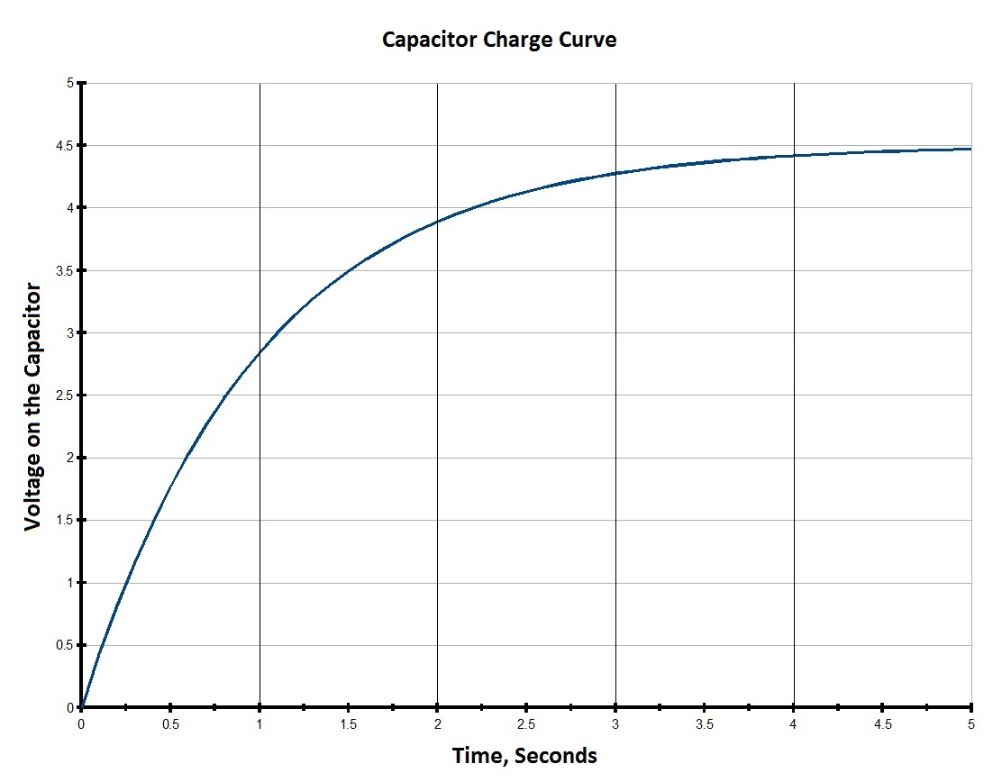
For the first part of this experiment, we’re going to use one 10K resistor and one 100µF (which equals 0.0001 farads). These two parts create a time constant of 1 second:

When charging our 100µF capacitor through a 10kΩ resistor, we can expect the voltage on the cap to rise to about 63% of the supply voltage in 1 time constant, which is 1 second. After 5 time constants (5 seconds in this case) the cap is about 99% charged up to the supply voltage, and it will follow a charge curve something like the plot below.
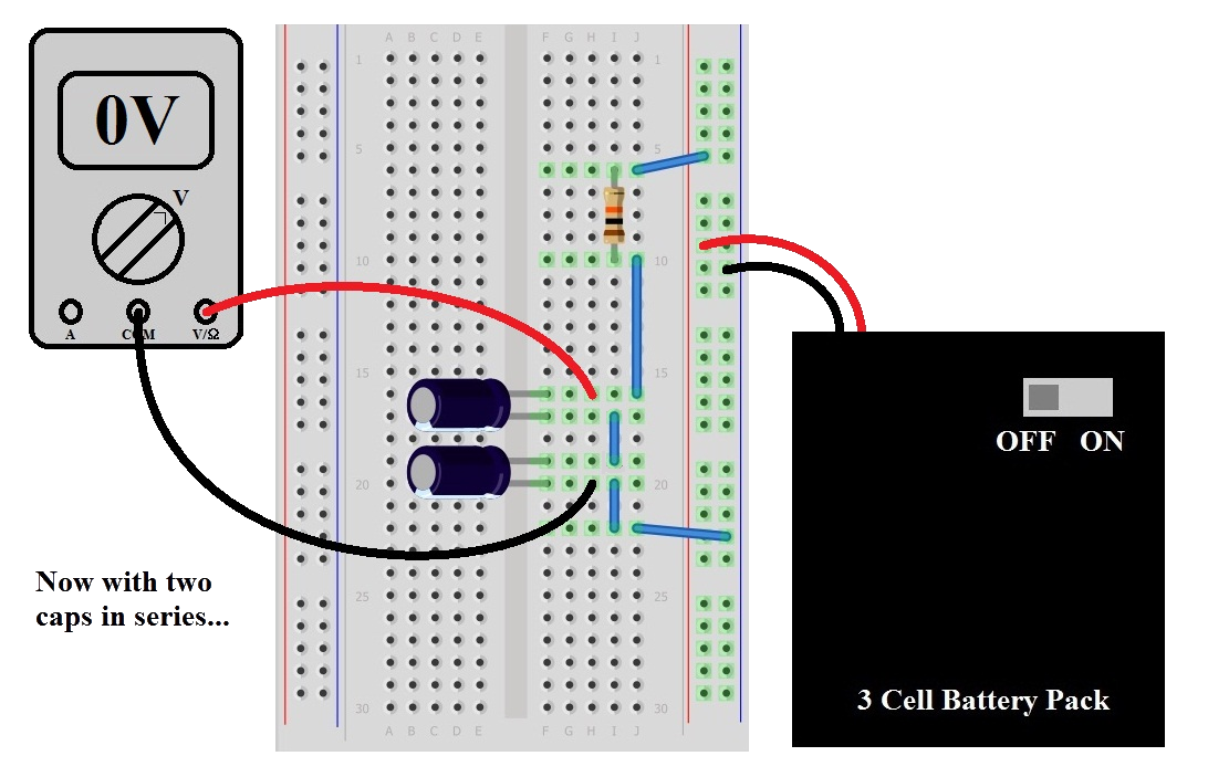
Now that we know that stuff, we’re going to connect the circuit in the diagram (make sure to get the polarity right on that capacitor!).
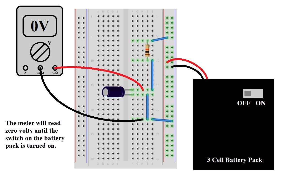
With our multimeter set to measure volts, check the output voltage of the pack with the switch turned on. That’s our supply voltage, and it should be something around 4.5V (it'll be a bit more if the batteries are new). Now connect the circuit, taking care that the switch on the battery pack is in the “OFF” position before plugging it into the breadboard. Also, take care that the red and black leads are going to the right places. If it’s more convenient, you can use alligator clips to attach the meter probes to the legs of the capacitor for measurement (you can also spread those legs out a bit to make it easier).
Once we’re satisfied that the circuit looks right and our meter’s on and set to read volts, flip the switch on the battery pack to “ON”. After about 5 seconds, the meter should read pretty close to the battery pack voltage, which demonstrates that the equation is right and we know what we’re doing. Now turn the switch off. It’s still holding that voltage pretty well, isn't it? That’s because there's no path for current to discharge the capacitor; we've got an open circuit. To discharge the cap, you can use another 10K resistor in parallel. After about 5 seconds, it will be back to pretty close to zero.
Experiment Time - Part 3, Even More...
Now we’re on to the interesting parts, starting with connecting two capacitors in series. Remember that we said the result of which would be similar to connecting two resistors in parallel. If this is true, we can expect (using product-over-sum)
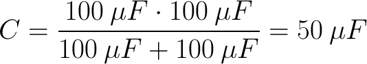
What’s that going to do to our time constant?

With that in mind, plug in another capacitor in series with the first, make sure the meter is reading zero volts (or there-abouts) and flip the switch to “ON”. Did it take about half as much time to charge up to the battery pack voltage? That’s because there’s half as much capacitance. The electron gas tank got smaller, so it takes less time to charge it up. A third capacitor is suggested for this experiment just to prove the point, but we’re betting the reader can see the writing on the wall.
Now we’ll try capacitors in parallel, remembering that we said earlier that this would be like adding resistors in series. If that’s true, then we can expect 200µF, right? Then our time constant becomes

This means that it will now take about 10 seconds to see the parallel capacitors charge up to the supply voltage of 4.5V.
For the proof, start with our original circuit of one 10kΩ resistor and one 100µF capacitor in series, as hooked up in the first diagram for this experiment. We already know that the capacitor is going to charge up in about 5 seconds. Now add a second capacitor in parallel. Make sure the meter is reading close to zero volts (discharge through a resistor if it isn't reading zero), and flip the switch on the battery pack to “ON”. Takes a long time, doesn't it? Sure enough, we made the electron gas tank bigger and now it takes longer to fill it up. To prove it to yourself, try adding the third 100µF capacitor, and watch it charge for a good, long time.
Series and Parallel Inductors
Series and Parallel Inductors
Cases where inductors need to be added either in series or in parallel are rather rare, but not unheard of. In any case, let’s address them just to be complete.
In a nutshell they add just like resistors do, which is to say they add with a plus sign when in series, and with product-over-sum when in parallel. The tricky part comes when they are placed close together so as to have interacting magnetic fields, whether intentionally or not. For this reason, it is preferable to have a single component rather than two or more, though most inductors are shielded to prevent interacting magnetic fields.
In any case, suffice it to say that they add like resistors do. More information than that regarding inductors is well beyond the scope of this tutorial.
Interested in learning more foundational topics?
See our Engineering Essentials page for a full list of cornerstone topics surrounding electrical engineering.

Resources and Going Further
Now that you're familiar with the basics of serial and parallel circuits, why not check out some of these tutorials?
- Voltage Dividers - One of the most basic, and recurring circuits is the voltage divider. This is a circuit which really builds upon the concepts explored in this tutorial.
- What is an Arduino? - Now that you've got the basics of circuits under your belt, you could head directly to learning about microcontrollers with one of the most popular platforms out there: Arduino.
- Switch Basics - We've talked about some of the more basic circuit elements in this tutorial, but this wasn't one of them. Switches are a critical component in just about every electronics project out there. Learn all about switches in this tutorial
- Sewing with Conductive Thread - Circuits don't have to be all breadboards and wire. E-textiles uses conductive thread to sew lights and other electronics into clothing or other fabric.