Connector Basics
 SFUptownMaker, bitsmashed
 Introduction
Connectors are used to join subsections of circuits together. Usually, a connector is used where it may be desirable to disconnect the subsections at some future time: power inputs, peripheral connections, or boards which may need to be replaced.
Covered in This Tutorial
In this tutorial we will go over:
- Basic connector terminology
- Categorize connectors into distinguishable categories
- Talk about the differences between connectors within those categories.
- Show how to identify polarized connectors
- Talk about which connectors are best suited for certain applications
Suggested Reading
You may find these concepts useful before starting on this tutorial:
What is a Circuit?
Voltage, Current, Resistance, and Ohm's Law
How to Power a Project
Working with Wire
Polarity
Connector Terminology
Before we get started discussing some commonly used connectors, let's explore the terminology used to describe connectors.
Gender
Gender - The gender of a connector refers to whether it plugs in or is plugged into and is typically male or female, respectively (kids, ask your parents for a more thorough explanation). Unfortunately, there are cases where a connector may be referred to as "male" when it would appear to be female; in the examples section, we'll point a few of those out as we discuss individual component types and explain why that's the case.
Polarity
Polarity - Most connectors can only be connected in one orientation. This trait is called polarity, and connectors which have some means to prevent them being connected wrong are said to be polarized, or sometimes keyed.
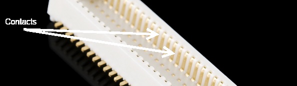
Contact
Contact - Contacts are the business portion of the connector. They are the metal parts which touch each other, forming an electrical connection. This is also where problems occur: the contacts can become soiled or oxidized, or the springiness required to hold the contacts together may fade with time.
Pitch
Pitch - Many connectors consist of an array of contacts in a repeated pattern. The pitch of the connector is the distance from the center of one contact to the center of the next. This is important, because there are many families of contacts which look very similar but may differ in pitch, making it difficult to know that you are purchasing the right mating connector.
Mating Cycles
Mating cycles - Connectors have a finite life, and connecting and disconnecting them is what wears them out. Datasheets usually present that information in terms of mating cycles, and it varies widely from one technology to another. A USB connector may have a lifetime in the thousands or tens of thousands of cycles, while a board-to-board connector designed for use inside of consumer electronics may be limited to tens of cycles. It's important that you select a connector with a suitable life for the application.
Mount
Mount - This one has the potential for being confusing. The term "mount" can refer to several things: how the connector is mounted in use (panel mount, free-hanging, board mount), what the angle of the connector is relative to its attachment (straight or right-angle), or how it is mechanically attached (solder tab, surface mount, through hole). We'll discuss this more in the examples section for each individual connector.
Strain Relief
Strain relief - When a connector mounts to a board or cable, the electrical connections tend to be somewhat fragile. It is typical to provide some kind of strain relief to transfer any forces acting on that connector to a more mechanically sound object than the fragile electrical connections. Again, there will be some good examples of this later on.
USB Connectors
USB connectors come in two flavors: host and peripheral. In the USB standard, there is a difference between the two, and the connectors on cables and devices reflect this. However, all USB connectors will have some things in common:
- Polarization - A USB connector can only nominally be inserted one way. It may be possible to force a connector in wrong, but that will result in damage to the device.
- Four contacts - All USB connectors have at least four contacts (although some may have five, and USB 3.0+ connectors have even more). These are for power, ground, and two data lines (D+ and D-). USB connectors are designed to transmit 5V, up to 500mA.
- Shielding - USB connectors are shielded, such that a metal shell which is not part of the electrical circuit is provided. This is important to keep the signal intact in environments with a lot of electrical "noise".
- Robust power connection - It's important for the power pins to make connection before the data lines, to avoid trying to power the device over the data lines. All USB connectors are designed with this in mind.
- Molded strain relief - All USB cables have plastic overmolding at the connector to prevent strain on the cable that could potentially damage the electrical connections.
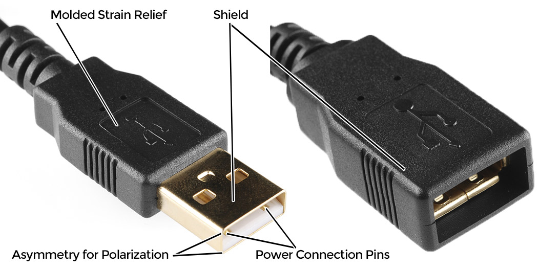
USB-A Connectors
USB-A female is the standard "host" connector type. This is found on computers, hubs, or any device intended to have peripherals plugged into it. It is also possible to find extension cables with a female A connector and a male A connector on the other end.

USB-A male is the standard "peripheral" connector type. Most USB cables will have one end terminating in a USB-A male connector, and many devices (such as keyboards and mice) will have a built-in cable terminated with a USB-A male connector. It's also possible to find USB-A male connectors that are board mountable, for devices like USB memory sticks.
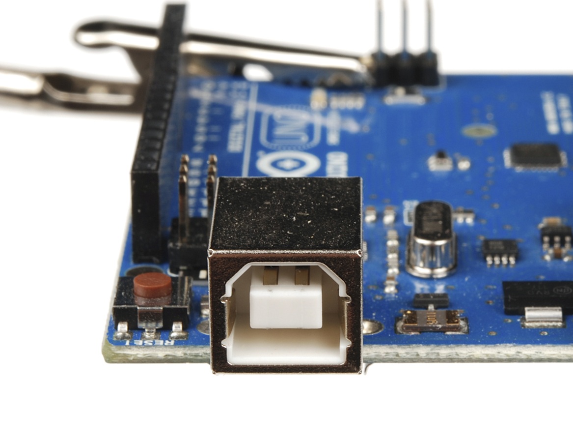
USB-B Connectors
USB-B female is a standard for peripheral devices. It's bulky, but robust, so in applications where size is not an issue, it's the preferred means for providing a removable connector for USB connectivity. It is usually a through-hole board mount connector, for maximum reliability, but there are panel-mount options for it as well.
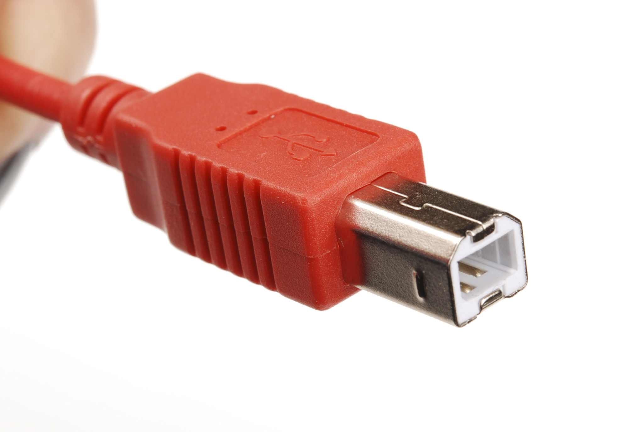
USB-B male is almost exclusively found at the end of a cable. USB-B cables are ubiquitous and inexpensive, which also contributes to the popularity of the USB-B connection.
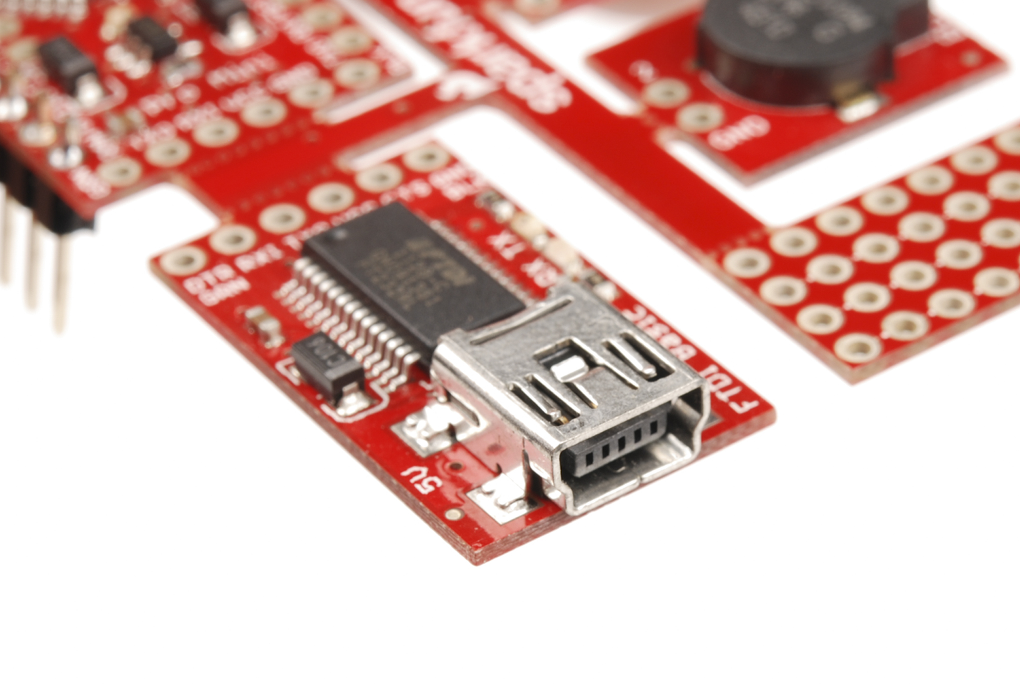
USB-Mini Connectors
The USB-Mini connection was the first standard attempt to reduce the size of the USB connector for smaller devices. USB-Mini female is typically found on smaller peripherals (MP3 players, older cellphones, small external hard drives), and is usually a surface mount connector, trading robustness for size. USB-Mini is slowly being phased out in favor of the USB-Micro connector.
USB-Mini male is another cable-only connector. As with USB-B, it's extremely common, and cables can be found cheaply almost anywhere.

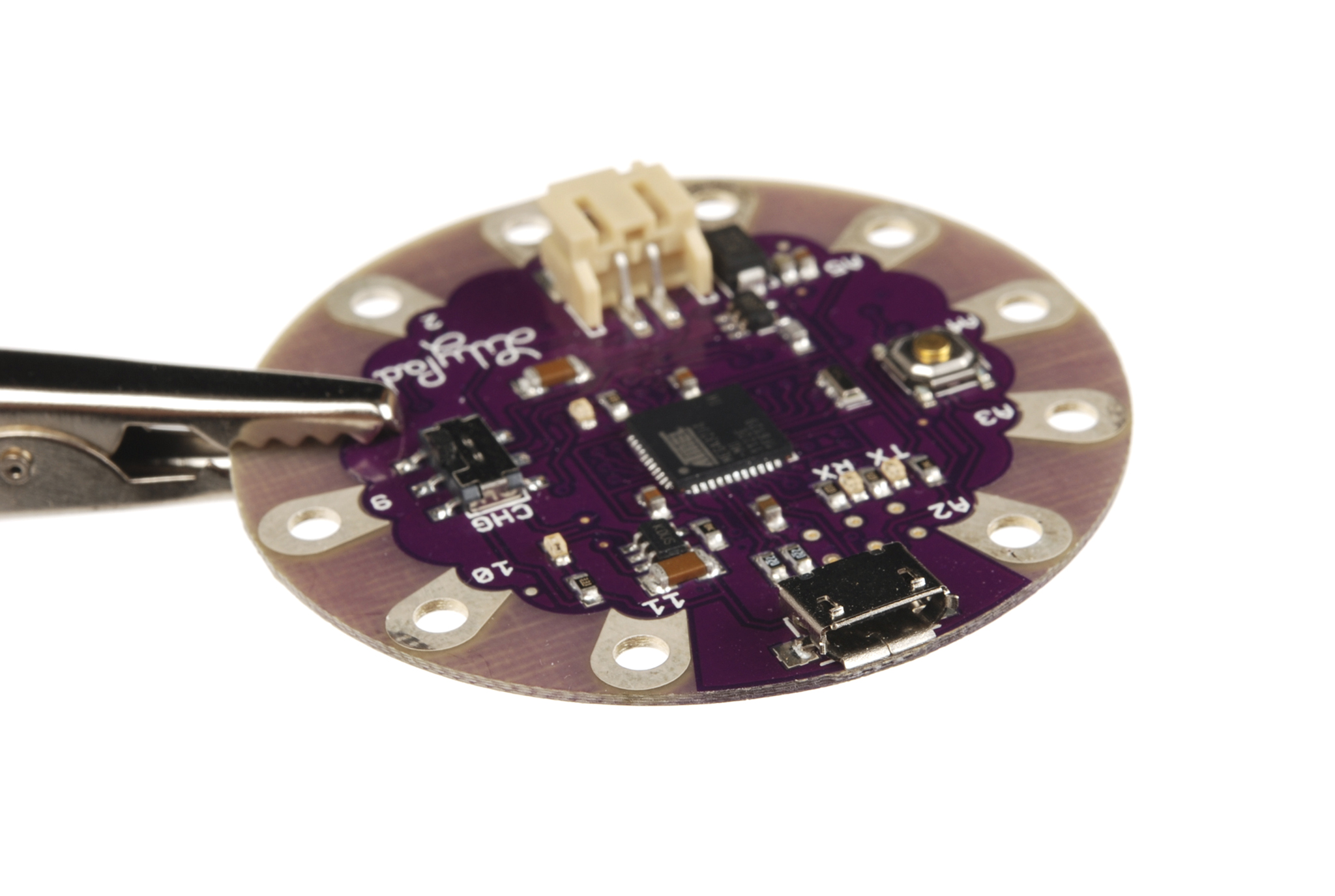
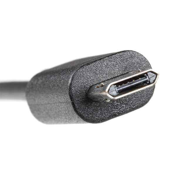
USB-Micro Connectors
USB-Micro is a fairly recent addition to the USB connector family. As with USB-Mini, the primary concern is size reduction, but USB-Micro adds a fifth pin for low-speed signalling, allowing it to be used in USB-OTG (On-the-go) applications where a device may want to operate as either a host or a peripheral depending on circumstances.
USB-Micro female is found on many newer peripherals, such as digital cameras and MP3 players. The adoption of USB-micro as a standard charge port for all new cellular phones and tablet computers means that chargers and data cables are becoming increasingly common, and USB-Micro is likely to supplant USB-Mini in the coming years as the small-factor USB connector of choice.
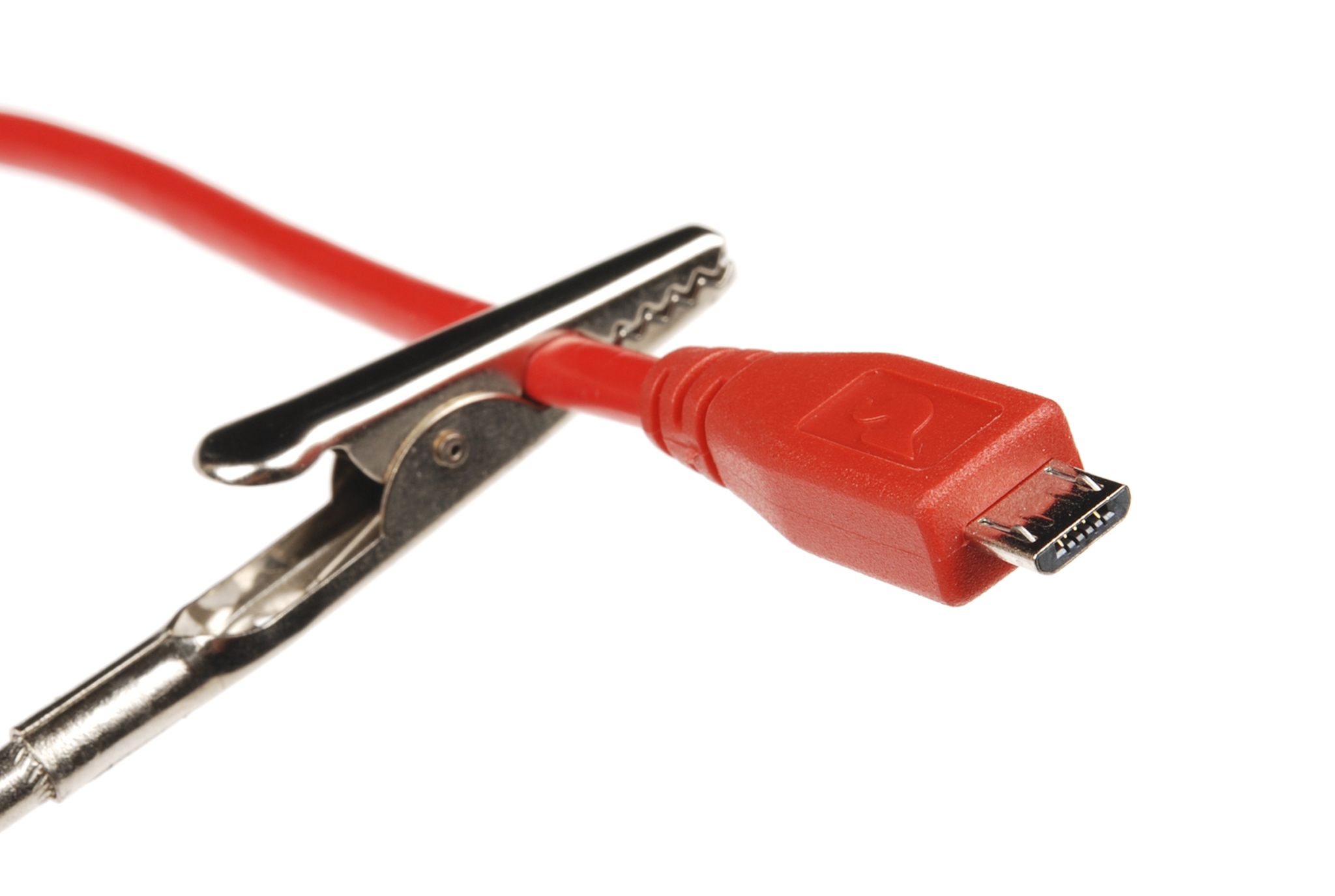
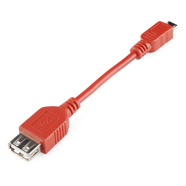
USB-Micro male is also a cable-only connector. There are generally two types of cables with USB-Micro male ends: one for connecting a device with a USB-Micro port as a peripheral to a USB host device and one for adapting the USB-Micro female port to a USB-A female port, to be used in USB-OTG capable devices.
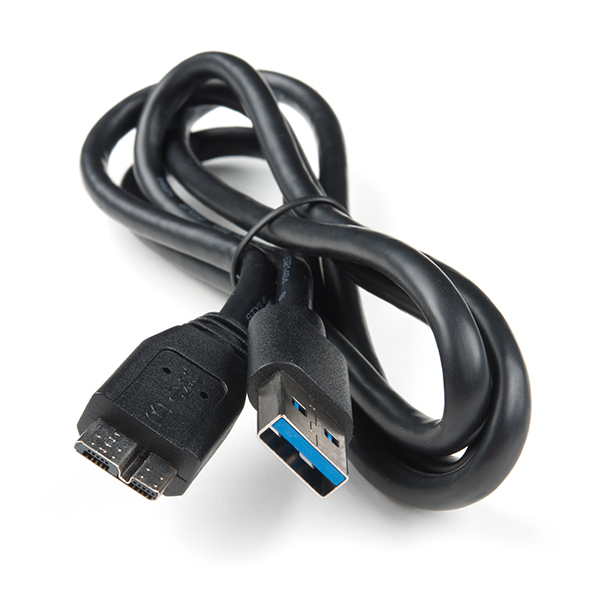
USB 3.0 micro-B Cable
USB 3.0 micro-B cables look similar to USB 2.0 micro-B connectors but they include additional pins for two differential pairs and a ground.
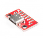
USB 3.1 C Cable
USB C packs 24 pins into the USB connector. Unlike the previous versions predecessors, this version is reversable! The design of the USB C cable also allows for current above 500mA for your power hungry devices.

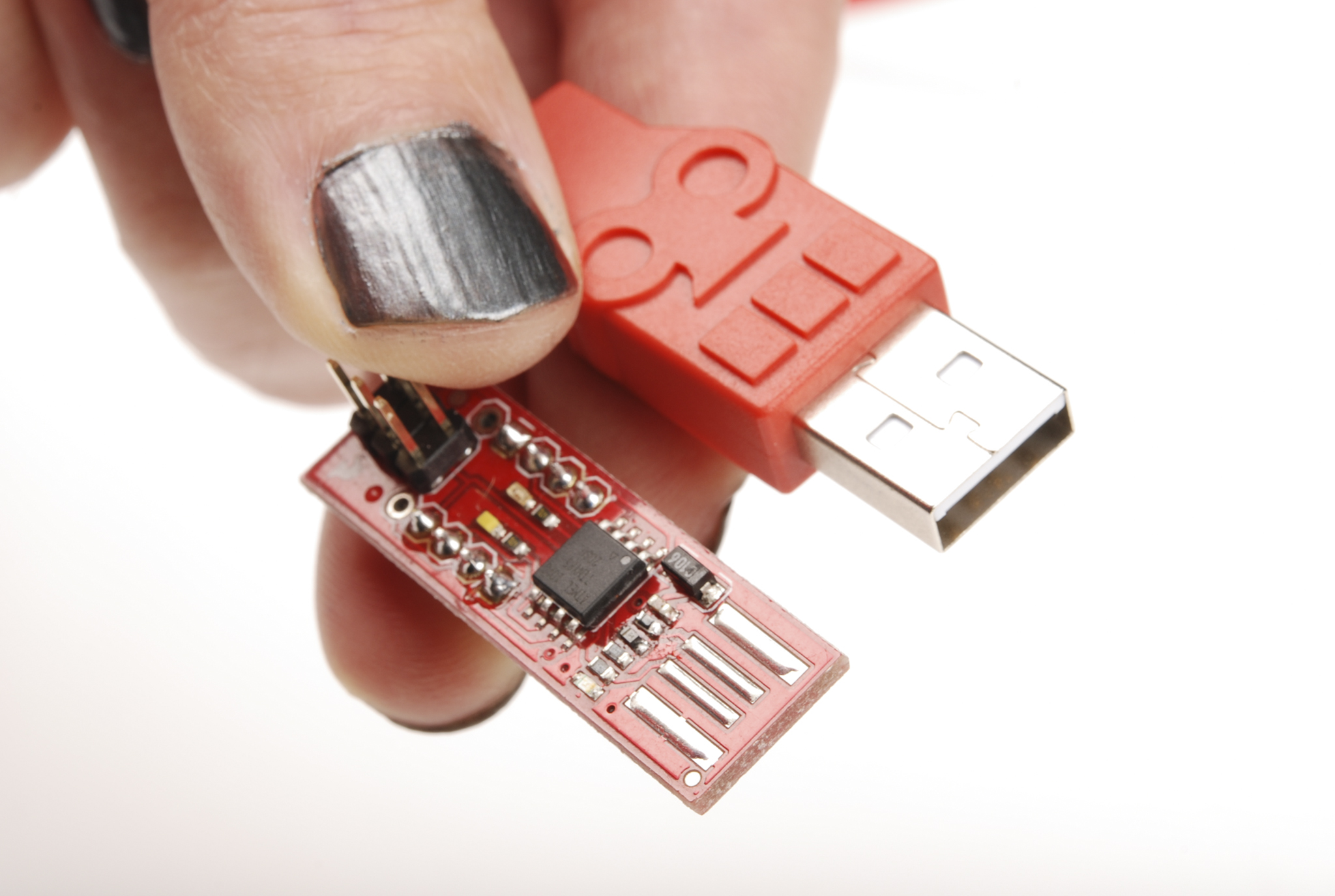
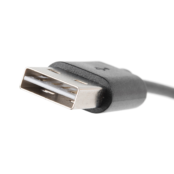
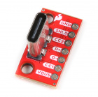
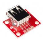
Reversible USB
With the advancements in technology and manufacturing, USB connectors can be inserted either way! Below are examples of a reversible type A and type micro-b connector from the catalog.
 |
 |
 |
 |
| Reversible Type A Connector End | Reversible Type Micro B Connector End |
If you are looking for a USB connector or cable, check out our USB Buying Guide or catalog.
Audio Connectors
Another familiar connector group are those used for audio-visual applications--RCA and phono. While these can't truly be considered to be of the same family, as the various USB connectors are, we'll consider both of them to be in the same vein.
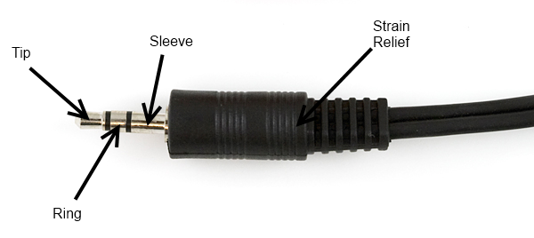
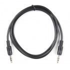
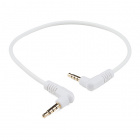
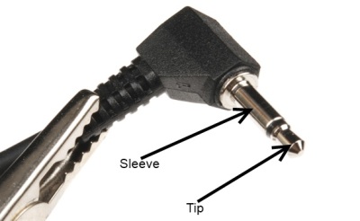
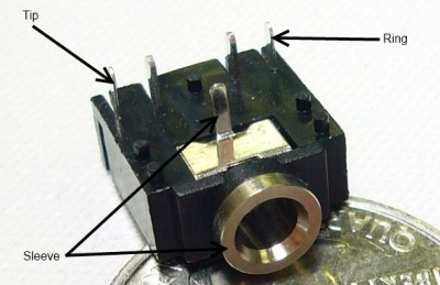
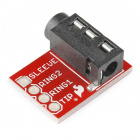
"Phone" Type Connectors
You'll probably immediately recognize the 1/8" version of this connector as a the plug on the end of a pair of headphones. These connectors actually come in three common sizes: 1/4" (6.35mm), 1/8" (3.5mm), and 2.5mm. ¼" size connectors find a lot of use in the professional audio and music community- most electric guitars and amplifiers have 1/4" tip-sleeve (TS) jacks on them. 1/8" tip-ring-sleeve (TRS) is very common as the connector for headphones or audio output signals on MP3 players or computers. Some cell phones will provide a 2.5mm tip-ring-ring-sleeve (TRRS) jack for connecting to headphones that also include a microphone for hands-free communications. Below are a few audio jacks that SparkFun carries in the catalog.
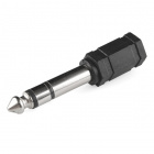
Audio Adapter - 3.5 mm to 1/4" Stereo
COM-11150The common availability of these connectors and cables makes them a good candidate for general purpose connectivity applications--for instance, long before USB, Texas Instruments graphing calculators used a 2.5mm TRS connector for a serial programming connector. It should be remembered that tip-sleeve connector types are not designed for carrying power; during insertion, the tip and the sleeve can be momentarily shorted together, which may damage the power supply. The lack of shielding makes them poor candidates for high-speed data, but low speed serial data can be passed through these connectors.
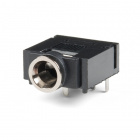
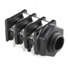
Below are a few audio sockets that SparkFun carries in the catalog.
RCA Connectors
Familiar as the home-stereo connector of choice for many decades, the RCA connector was introduced in the 1940s by RCA for home phonographs. It is slowly being supplanted by connections like HDMI in the audio-visual realm, but the ubiquity of the connectors and cables makes it a good candidate for home-built systems. It will be a long time before it is obsolete.
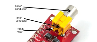
Female RCA connectors are usually found on devices, although it is possible to find extension or conversion cables with female jacks on them. Most RCA connectors are connected to one of four types of signals: component video (PAL or NTSC, depending on where the equipment was sold), composite video, stereo audio, or S/PDIF audio.
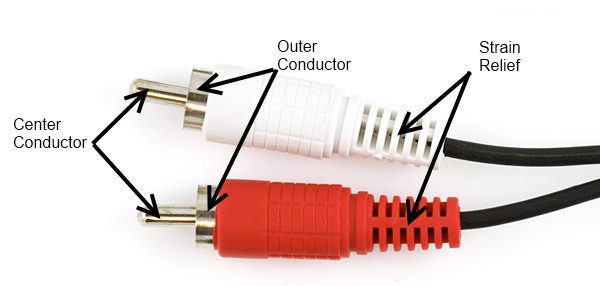
Male RCA connectors are usually found on cables.
Power Connectors
While many connectors carry power in addition to data, some connectors are used specifically to provide power connections to devices. These vary widely by application and size, but we will only focus on some of the most common ones here.
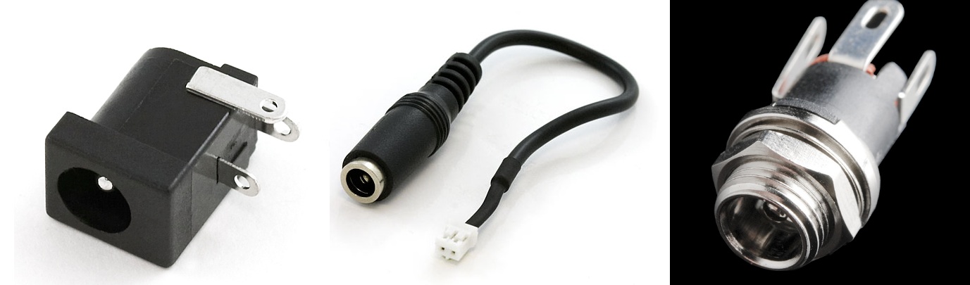
Barrel Connectors
Barrel connectors are typically found on low-cost consumer electronics which can be plugged into wall power via bulky AC wall adaptors. Wall adaptors are widely available, in a variety of power ratings and voltages, making barrel connectors a common means for connecting power to small projects.
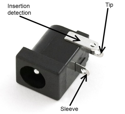
The female barrel connector, or "jack", can be purchased in several varieties: PCB mounted (surface mount or through hole), cable mount, or panel mount. Some of these connectors will have an additional contact that allows the application to detect whether a power supply is plugged into the barrel jack or not, thus allowing the device to bypass batteries and save battery life when running on external power.
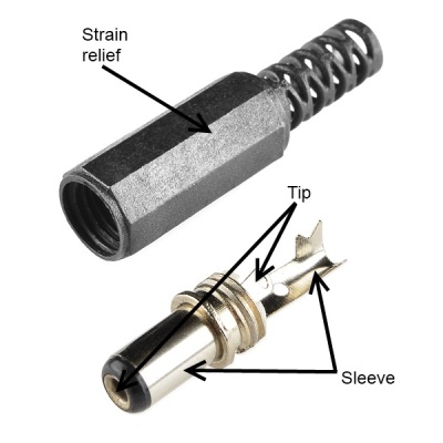
The male barrel connector, or "plug", is usually only found in a wire termination variety, although there are multiple methods of attaching the plug to the end of the wire. It's also possible to get plugs that come pre-attached to a cable.
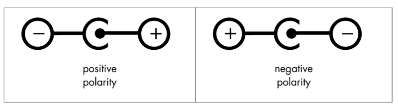
Barrel connectors provide only two connections, frequently referred to as "pin" or "tip" and "sleeve". When ordering, there are three differentiating characteristics of a barrel connection- inner diameter (the diameter of the pin inside the jack), outer diameter (the diameter of the sleeve on the outside of the plug), and polarity (whether the sleeve voltage is higher or lower than the tip voltage).
Sleeve diameter is most commonly either 5.5mm or 3.5mm.
Pin diameter is contingent upon sleeve diameter; a 5.5mm sleeve will have either a 2.5mm or 2.1mm pin. Unfortunately, this means that a plug designed for a 2.5mm pin will fit in a 2.1mm jack, but that the connection will be, at best, intermittent. 3.5mm sleeve plugs usually mate to a jack with a 1.3mm pin.
Polarity is the final aspect to consider; most often, the sleeve will be considered 0V and the tip will be a positive voltage relative to the sleeve. Many devices will have a small diagram indicating the polarity expected by the device; care should be taken to adhere to this, as an improper power supply may damage the device.
Plugs of both sleeve sizes are usually 9.5mm long, but longer and shorter ones do exist. All SparkFun products use a negative 5.5mm sleeve and a positive 2.1mm pin; we recommend sticking to that standard where possible, as it seems to be the most common flavor found in the wild.
"Molex" Connectors
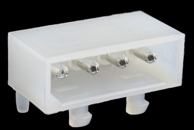
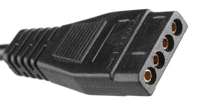
Most computer hard drives, optical drives, and other internal peripherals get power through what is typically called a "Molex" connector. To be more accurate, it's a Molex series 8981 connector--Molex is actually the name of the company which initially designed this connector back in the 1950s--but common usage has denuded that fact somewhat.
Molex connectors are designed to carry a lot of current: up to 11A per pin. For projects where a lot of power may be needed--a CNC machine, for instance, or a 3D printer- a very common method for powering the project is to use a desktop PC power supply and connecting the various system circuits through Molex connectors.
The Molex connector is one where the male/female terminology is a bit odd. The female connector is usually found on the end of a cable, and it slips inside of a plastic shell which surrounds the male pins on the male connector. Usually, the connectors are press-fit only, and very, very tight--they are intended to be connected and disconnected only a few times and, as such, are a bad choice for systems where connections will frequently be changed.
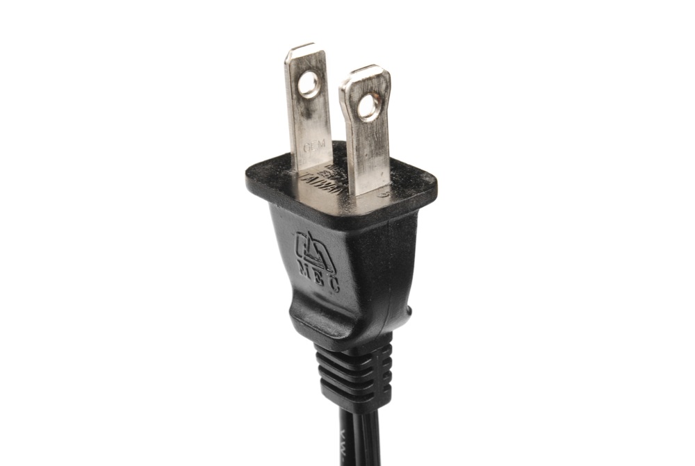
IEC Connector
As with the Molex connector, this is a case where a generalized component name has come to be synonymous with a single, particular item. IEC connector usually refers to the power supply inlet which is commonly seen on desktop PC power supplies. Strictly speaking, that's an IEC 60320-1 C13 (female) and C14 (male) connector.
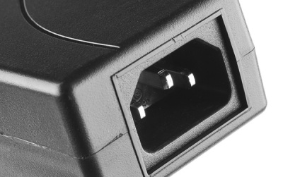
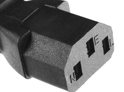
IEC connectors are used almost exclusively for AC power input. The nice thing about using one on a project is that IEC-to-wall cables are extremely common and available with localized wall plugs for most international locations!
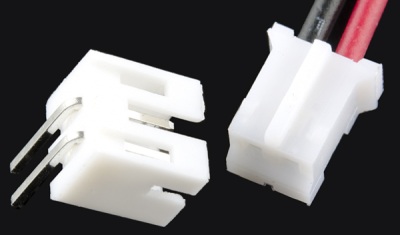
JST Connector
At SparkFun, we frequently refer to "2.0mm JST Connectors". This is yet another generalization of a specific product- JST is a Japanese company which makes high-quality connectors, and our 2.0mm JST connector of choice is the PH series two-position polarized connector.
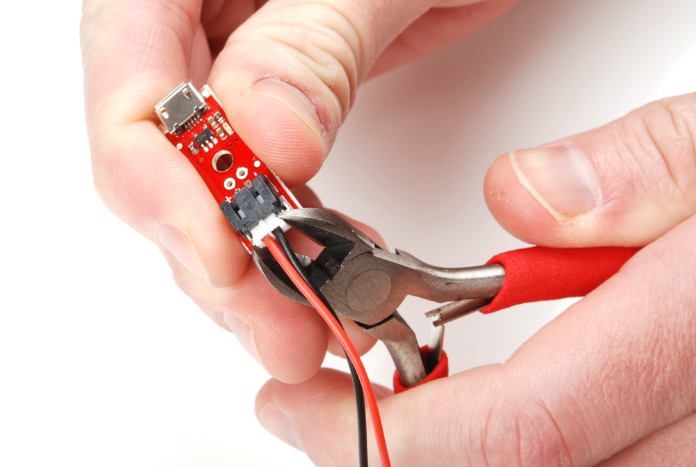
All of SparkFun's single-cell lithium-polymer ion batteries come standard with this type of JST connector, and many of our boards include this connector (or a footprint for it) as a power supply input. It has the advantage of being compact, durable, and difficult to connect backwards. Another feature, which can be an advantage or a disadvantage, depending on how you look at it, is that the JST connector is wicked hard to disconnect (although a carefully applied diagonal cutter can be helpful!) once it's mated. While this makes it unlikely to fail during use, it also means that disconnecting the battery for charging can damage the battery connector.
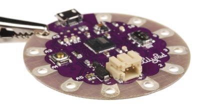
There are PH series connectors with more than two positions; SparkFun even sells them. However, our most frequent application is for the 2-position battery connection.
SMA Antenna Connectors
Next up is the explanation of the confusing naming conventions for SMA connectors. If you would rather not understand why the convention is the way it is, you can just look at the 4 pictures and move on. Otherwise, have fun with the read!
RF Connector Conventions
SparkFun uses SMA-type connectors on a few boards that need a 50 Ohm impedance connection to an external antenna (GPS, Bluetooth, cellular, Nordic, and XBee). However, some of these boards use different genders and polarities of the SMA connector. Therefore, we need different antennas to match the specific gender or polarity of the RF connections.
There are 4 different types of SMA connectors using a combination of gender, which refers to the center pin and polarity, which refers to…..uh, this is where it gets confusing. Wikipedia tries to explain it. But from what I have found there was an original “old” design for SMA connectors.
SMA Connectors
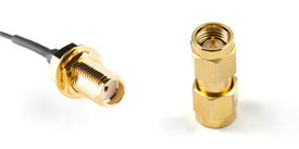
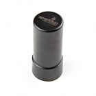
The original SMA design called for two compliant connectors:
 |
 |
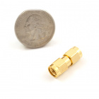
| SMA Male Center Pin, Inner Threads |
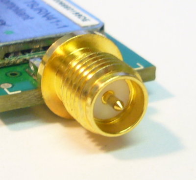
SMA Female Center Hole, Outer Threads |
The above two connectors were designed to be used together, but there was a problem with this configuration and the FCC started moving towards Part 15 compliance. All this means is that all the SMA RF connectors are changing gender (center pin). Really annoying for those of us who need to mate an antenna to an RF device. The FCC gender change was instituted to prevent home users from damaging RF equipment (think home WiFi) when screwing on an antenna. If all antennas are female, there is no way to damage the center connector.
There is one consistency however; all antennas, cables or anything was being attached to a potential stationary object used an outer nut or inner thread design and all stationary devices used the outer thread design. This applies for all SparkFun products. All of our antennas are either SMA male or RP-SMA female. All of our boards are either SMA female or RP-SMA male.
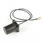
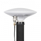
RP-SMA Connectors
The only thing that changed with the Part 15 compliance was the center pin, thus reversing the polarity of the connection and forming a “new” standard; the reversed polarized SMA (RP-SMA). The RP (reverse polarity) is named after its “thread gender” and has an opposite-gender pin.
The next two photos are considered reversed polarized (RP-SMA).
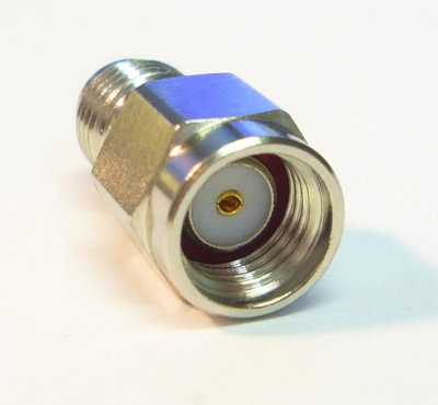 |
 |
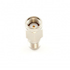
| RP-SMA Male Center Hole, “Male” Inner Threads |
RP-SMA Female Center Pin, “Female” Outer Threads |
If the board does not have a u.FL connector to attach an external antenna, SparkFun RF boards and antennas will use a combination of the old (SMA) and new (RP-SMA):
Cellular and GPS (900/1700/1800MHz and 1.57542GHz respectively) generally use the old convention: SMA male for the antennas and SMA female for the modules.
Anything 2.4GHz (Bluetooth, ZigBee, WiFi, and Nordic) generally use the new convention: RP-SMA male on the antennas and RP-SMA female on the modules.
Really, you can ignore the gender descriptor. If you have a RP-SMA board or module, you need a RP-SMA antenna and so forth for SMA. Pretty simple, right?! Just make sure to match the antenna frequency with the your board.
And just in case if you happen to find the old and new mixing, we sell a SMA male to RP-SMA male and a RP-SMA female to RP-SMA male connector that will most combinations of antenna and connector to be mated.
I hope you are not thoroughly confused!
If you are looking for an RF connector or antenna, check out our RF Connector Buying Guide or catalog.
Pin Header Connectors
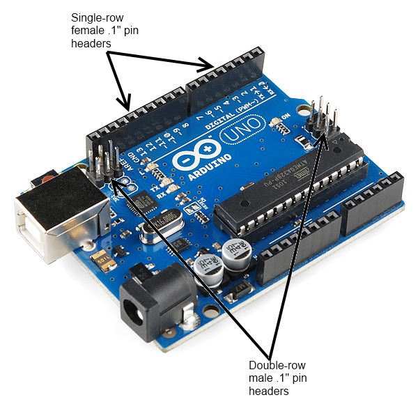
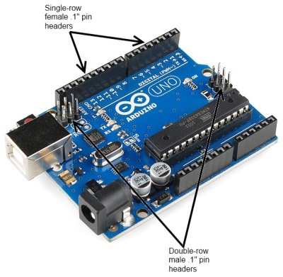
Pin header connectors comprise several different means of connection. Generally, one side is a series of pins which are soldered to a PCB, and they can either be at a right-angle to the PCB surface (usually called "straight") or parallel to the board's surface (confusingly referred to as "right-angle" pins). Such connectors come in a variety of pitches, and may have any number of individual rows of pins.
The most commonly seen pin headers are 0.1" (2.54mm) single or double row connectors. This is a standard breadboard compatible pitch. These come in male and female versions, and are the connectors used to connect Arduino boards and shields together. Users can easily connect jumper wires to breadboards.
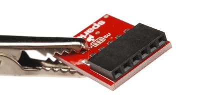
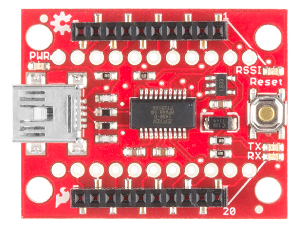
Other pitches are not uncommon; for instance, the XBee wireless module uses a 2.0mm pitch version of the same connector. Below is a top view showing the SMD 2.00mm pitched female header soldered on the board. As you can see, the two rows of plated through holes for standard breadboard compatible headers next to the headers are spaced at 0.1" (2.54mm) apart.
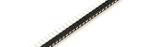
A common variation on this part is a "machine pin" version. While the normal version is formed out of stamped and folded sheet metal, machine pin connectors are formed by tooling the metal into the desired shape. The result is a more robust connector, with a better joint and longer life, making it somewhat more expensive.
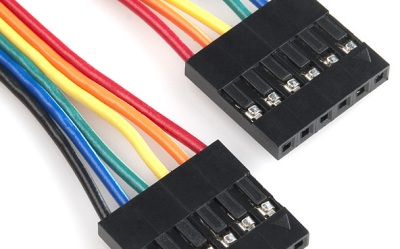
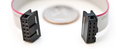
Cables made to connect to these pin headers are usually one of two types: individual wires with crimp connectors on them or ribbon cables with insulation displacement connectors. These can simply be clamped onto the end of a ribbon cable, which creates a connection to each one of the conductors in the ribbon cable. Generally, cables are only available as female gender and expect a male pin to mate with.
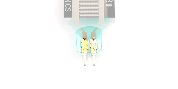
Flexible circuits can also use solder tabs spaced with the standard 0.1" pitch. These tabs are stapled through a flexible substrate in order to make contact with the semi-conductive material.
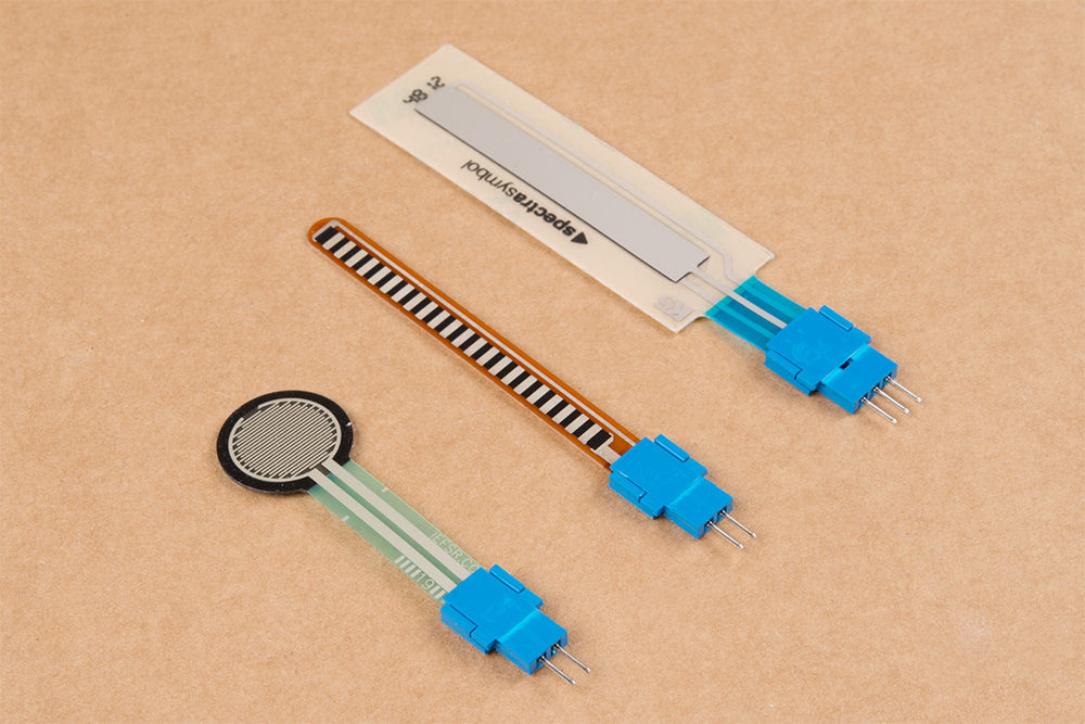
Depending on your project application and skill set, there are a few methods of connecting to the solder tabs. Users can insert the solder tabs into breadboards or solder directly to the pins However, the thin solder tabs can break over time when bent excessively and can become loose in a breadboard socket. Flexible sensors can also be sensitive to heat due to the semi-conductive material. As an alternative, the Amphenol FCI Clincher connectors were designed with thicker leads and breadboard compatible sockets for a more reliable connection.
Temporary Connectors
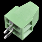
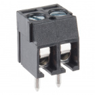
Screw Terminals
In some cases, it may be desirable to be able to connect bare, unterminated wire to a circuit. Screw terminals provide a good solution for this. They are also good for situations in which a connection should be capable of supporting multiple different connecting devices.
The downside of screw terminals is that they can come undone fairly easily, leaving a bare wire waving around in your circuit. A small dab of hot glue can address this without being too difficult to remove later.
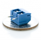
Screw terminals are typically designed for a narrow range of wire gauges, and wires that are too small can be as big a problem as wires that are too big. SparkFun carries four types of screw terminal – a 2.54mm (0.1" breadboard standard), a 3.5mm, 5mm, and 10mm pitch version.
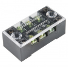
Terminal Block - 3 Position (15A, 600V)
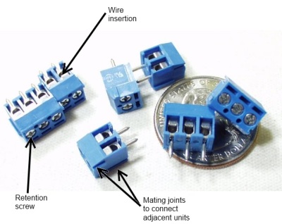
PRT-13060Most screw terminals are highly modular, and they can easily be extended at the same pitch by simply connecting two or more smaller sections together.
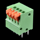
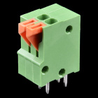
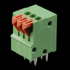
Spring Terminals
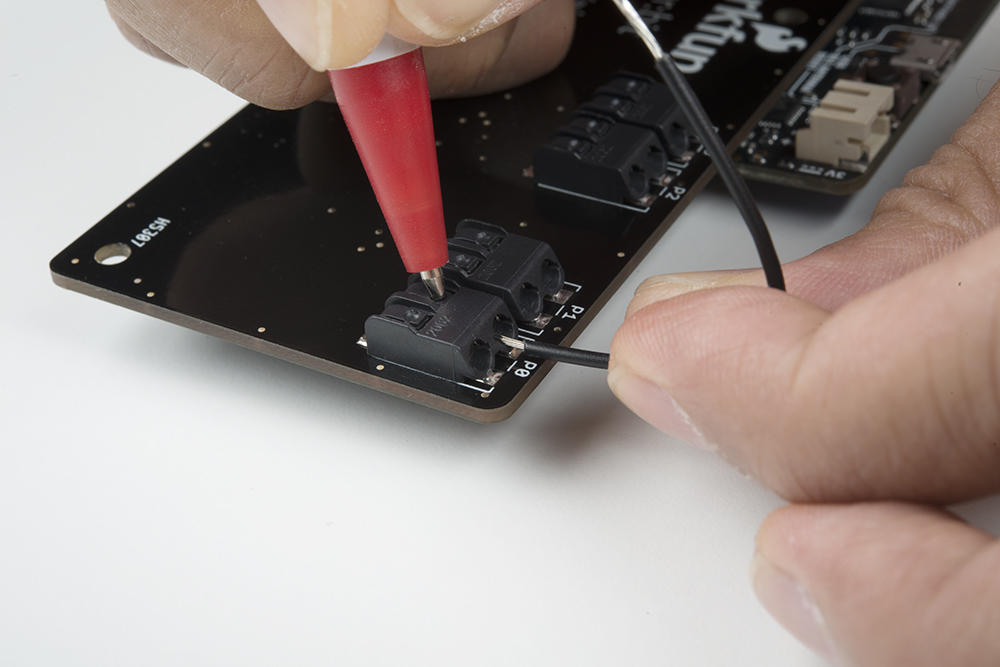
Alternatives to screw terminals include spring terminals (a.k.a. "push-in", "cage-clamp", or "poke-home" connectors). Spring terminals work in a similar fashion as screw terminals. However, instead of tightening a screw to make a connection with piece of wire, a spring clamps together pieces of metal together.
Spring terminals provide an alternative to screw terminals. They work better in environments with a lot of vibrations (i.e. automotive applications) or when a wire expanding/contracting due to temperature cycling. Additionally, the tension is automatically adjusted to the wire gauge (assuming it is within the accepted wire thickness) as opposed to variances in tension when a user tightens the screw terminal. Below are a few spring terminal connectors that SparkFun carries in the catalog.
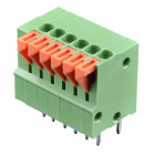
Spring Terminals - PCB Mount (6-Pin)
PRT-08077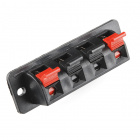
Speaker Terminal - 4 Spring
COM-11145Certain boards (like the gamer:bit, LumiDrive, and Qwiic MP3 Trigger to name a few) are populated with a spring terminal for easy access to I/O pins. Those witth the poke-home connectors can pushed down on the tab using a ball-point pen or a Phillips head screwdriver.
Banana Connector
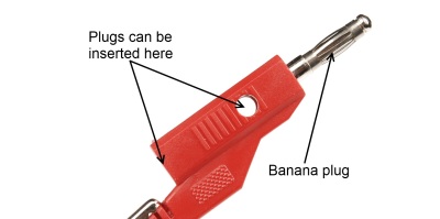
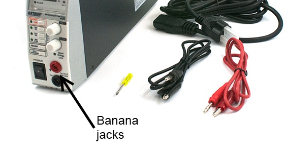
Most pieces of power test equipment (multimeters, power supplies) have a very simple connector called a "banana jack" on it. These mate to "banana plugs", crimped, sprung metal plugs, meant to make a single power connection. They are frequently available in a stackable configuration and can be easily connected to any type of wire. They are capable of carrying several amps of current and are inexpensive.
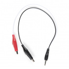
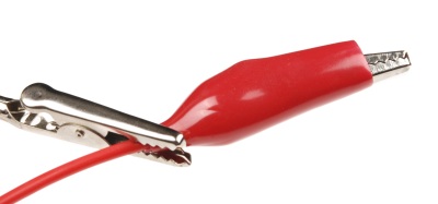
Alligator Clip
Named for obvious reasons, alligator clips are good for test connections to posts or bare wires. They tend to be bulky, easily cause shorts to nearby bare metal, and have a reasonably poor grip that can be easily compromised. They are primarily used for low-cost connections during debugging.
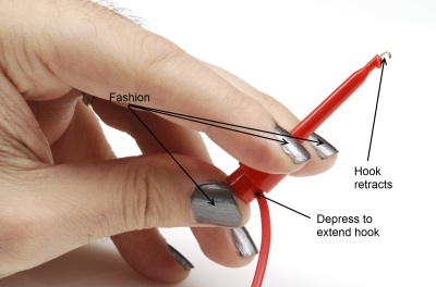
IC Clip (or IC Hook)
For more delicate probing operations, there are a variety of IC clips on the market. These are sized to allow a user to clip them onto the pins of an IC without contacting adjacent pins; some of them are delicate enough to be clipped onto even fine-pitched SMD component legs. These smaller clips can be found on logic analyzers as well as test leads, which are great for prototyping or troubleshooting circuits.
Other Connectors
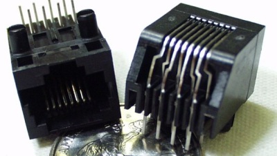
RJ-type Modular Connectors
Registered jack connectors are standard for telecommunications equipment into a local exchange. The names one normally hears associated with them (RJ45, RJ12, etc) are not necessarily correct, as the RJ designator is a based on a combination of the number of positions, the number of conductors actually present, and the wiring pattern. For example, while the ends of a standard ethernet cable are usually referred to as "RJ45", RJ45 actually implies not only an 8 position, 8 conductor modular jack, it also implies that it is wired for ethernet.
These modular connectors can be very useful, since they combine ready availability, multiple conductors, moderate flexibility, low cost, and moderate current carrying capacity. While not originally intended to deliver a great deal of power, these cables can be used to deliver data and a couple of hundred milliamps from one device to another. Care should be taken to ensure that jacks provided for applications like this are not connected to conventional ethernet ports, as damage will result.
D-sub Type Connectors
Named for the shape of their shell, D-subminiature connectors are a classic standard in the computing world. There are four very common varieties of this connector: DA-15, DB-25, DE-15, and DE-9. The pin number indicates the number of connections provided, and the letter combination indicates the size of the shell. Thus, DE-15 and DE-9 have the same shell size, but a different number of connections.
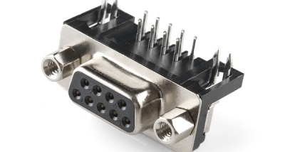
DB-25 and DE-9 are the most useful to the hardware hacker; many desktop computers still include at least one DE-9 serial port, and often one DB-25 parallel port. Cables terminated with DE-9 and DB-25 connectors are widely available, too. As with the modular connector above, these can be used to provide power and point-to-point communications between two devices. Again, since the common usage of these cables does not include power transmission, it is very important that any repurposing of the cables be done cautiously, as a non-standard device plugged into a standard port can easily cause damage.
Resources and Going Further
You should now have a good idea which connectors are suited best for certain applications and which connectors will be useful to you in your next project. Please check out these other links to lean more about connectors.
- Giant database of connectors and pinouts - Everything you never wanted to know about pretty much any connector, ever. A good site for basic info about connectors, but often quite shy on interface details.
- Wikipedia article on registered jack connectors - More on the confusing world of the registered jack (RJ) connector, which is often misunderstood and misused.
- Wikipedia article on D-subminiature connectors - As with the registered jack connector, misinformation abounds on the D-subminiature standard. Wikipedia has a great article about it.
- Mouser electronics catalog - Browsing an electronics supplier catalog is often a great place to start looking for the name of an unidentified connector; Mouser's enhanced online catalog is just as good as the print version, with fewer papercuts!
Interested in learning more foundational topics?
See our Engineering Essentials page for a full list of cornerstone topics surrounding electrical engineering.

If you'd like top explore more SparkFun tutorials, check out these other offerings:
Serial Communication
Serial Peripheral Interface (SPI)
What is an Arduino?
Logic Levels
Electric Power
I2C
Alternating Current (AC) vs. Direct Current (DC)
Three Quick Tips About Using U.FL
Or check out these related blog post: