Serial Peripheral Interface (SPI)
 MikeGrusin
 Introduction
Serial Peripheral Interface (SPI) is an interface bus commonly used to send data between microcontrollers and small peripherals such as shift registers, sensors, and SD cards. It uses separate clock and data lines, along with a select line to choose the device you wish to talk to.
Suggested Reading
Stuff that would be helpful to know before reading this tutorial:
Serial Communication
Binary
Shift Registers
Logic Levels

Start Connecting Components
Protocols like SPI let microcontrollers communicate with sensors, displays, and other hardware. The SparkFun Inventor's Kit includes guided projects that help you start wiring and programming real electronic systems.
Start Building with the Inventor's KitWhat's Wrong with Serial Ports?
A common serial port, the kind with TX and RX lines, is called "asynchronous" (not synchronous) because there is no control over when data is sent or any guarantee that both sides are running at precisely the same rate. Since computers normally rely on everything being synchronized to a single “clock” (the main crystal attached to a computer that drives everything), this can be a problem when two systems with slightly different clocks try to communicate with each other.
To work around this problem, asynchronous serial connections add extra start and stop bits to each byte help the receiver sync up to data as it arrives. Both sides must also agree on the transmission speed (such as 9600 bits per second) in advance. Slight differences in the transmission rate aren't a problem because the receiver re-syncs at the start of each byte.
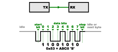
(By the way, if you noticed that "11001010" does not equal 0x53 in the above diagram, kudos to your attention to detail. Serial protocols will often send the least significant bits first, so the smallest bit is on the far left. The lower nybble is actually 0011 = 0x3, and the upper nybble is 0101 = 0x5.)
Asynchronous serial works just fine, but has a lot of overhead in both the extra start and stop bits sent with every byte, and the complex hardware required to send and receive data. And as you've probably noticed in your own projects, if both sides aren't set to the same speed, the received data will be garbage. This is because the receiver is sampling the bits at very specific times (the arrows in the above diagram). If the receiver is looking at the wrong times, it will see the wrong bits.
A Synchronous Solution
SPI works in a slightly different manner. It's a "synchronous" data bus, which means that it uses separate lines for data and a "clock" that keeps both sides in perfect sync. The clock is an oscillating signal that tells the receiver exactly when to sample the bits on the data line. This could be the rising (low to high) or falling (high to low) edge of the clock signal; the datasheet will specify which one to use. When the receiver detects that edge, it will immediately look at the data line to read the next bit (see the arrows in the below diagram). Because the clock is sent along with the data, specifying the speed isn't important, although devices will have a top speed at which they can operate (We'll discuss choosing the proper clock edge and speed in a bit).
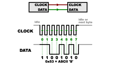
One reason that SPI is so popular is that the receiving hardware can be a simple shift register. This is a much simpler (and cheaper!) piece of hardware than the full-up UART (Universal Asynchronous Receiver / Transmitter) that asynchronous serial requires.
Receiving Data
| Obsolete Name | Replacement Name |
|---|---|
| Master | Controller |
| Slave | Peripheral |
| MISO | POCI |
| MOSI | PICO |
| SS | CS |
You might be thinking to yourself, self, that sounds great for one-way communications, but how do you send data back in the opposite direction? Here's where things get slightly more complicated.
In SPI, only one side generates the clock signal (usually called CLK or SCK for Serial ClocK). The side that generates the clock is called the "controller", and the other side is called the "peripheral". There is always only one controller (which is almost always your microcontroller), but there can be multiple peripherals (more on this in a bit).
When data is sent from the controller to a peripheral, it's sent on a data line called PICO, for "Peripheral In / Controller Out". If the peripheral needs to send a response back to the controller, the controller will continue to generate a prearranged number of clock cycles, and the peripheral will put the data onto a third data line called POCI, for "Peripheral Out / Controller In".
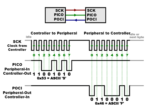
Notice we said "prearranged" in the above description. Because the controller always generates the clock signal, it must know in advance when a peripheral needs to return data and how much data will be returned. This is very different than asynchronous serial, where random amounts of data can be sent in either direction at any time. In practice this isn't a problem, as SPI is generally used to talk to sensors that have a very specific command structure. For example, if you send the command for "read data" to a device, you know that the device will always send you, for example, two bytes in return. (In cases where you might want to return a variable amount of data, you could always return one or two bytes specifying the length of the data and then have the controller retrieve the full amount.)
Note that SPI is "full duplex" (has separate send and receive lines), and, thus, in certain situations, you can transmit and receive data at the same time (for example, requesting a new sensor reading while retrieving the data from the previous one). Your device's datasheet will tell you if this is possible.
Chip Select (CS)
There's one last line you should be aware of, called CS for Chip Select. This tells the peripheral that it should wake up and receive / send data and is also used when multiple peripherals are present to select the one you'd like to talk to.
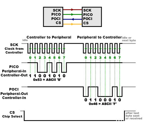
The CS line is normally held high, which disconnects the peripheral from the SPI bus. (This type of logic is known as “active low,” and you’ll often see used it for enable and reset lines.) Just before data is sent to the peripheral, the line is brought low, which activates the peripheral. When you're done using the peripheral, the line is made high again. In a shift register, this corresponds to the "latch" input, which transfers the received data to the output lines.
Multiple Peripherals
There are two ways of connecting multiple peripherals to an SPI bus:
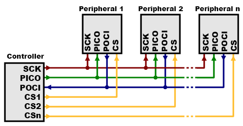
- In general, each peripheral will need a separate CS line. To talk to a particular peripheral, you'll make that peripheral's CS line low and keep the rest of them high (you don't want two peripherals activated at the same time, or they may both try to talk on the same POCI line resulting in garbled data). Lots of peripherals will require lots of CS lines; if you're running low on outputs, there are binary decoder chips that can multiply your CS outputs.
- On the other hand, some parts prefer to be daisy-chained together, with the POCI (output) of one going to the PICO (input) of the next. In this case, a single CS line goes to all the peripherals. Once all the data is sent, the CS line is raised, which causes all the chips to be activated simultaneously. This is often used for daisy-chained shift registers and addressable LED drivers.
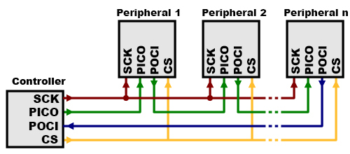
Note that, for this layout, data overflows from one peripheral to the next, so to send data to any one peripheral, you'll need to transmit enough data to reach all of them. Also, keep in mind that the first piece of data you transmit will end up in the last peripheral.
This type of layout is typically used in output-only situations, such as driving LEDs where you don't need to receive any data back. In these cases you can leave the controller's POCI line disconnected. However, if data does need to be returned to the controller, you can do this by closing the daisy-chain loop (blue wire in the above diagram). Note that if you do this, the return data from peripheral 1 will need to pass through all the peripherals before getting back to the controller, so be sure to send enough receive commands to get the data you need.
Programming for SPI
Many microcontrollers have built-in SPI peripherals that handle all the details of sending and receiving data, and can do so at very high speeds. The SPI protocol is also simple enough that you (yes, you!) can write your own routines to manipulate the I/O lines in the proper sequence to transfer data. (A good example is on the Wikipedia SPI page.)
If you're using an Arduino, there are two ways you can communicate with SPI devices:
You can use the shiftIn() and shiftOut() commands. These are software-based commands that will work on any group of pins, but will be somewhat slow.
Or you can use the SPI Library, which takes advantage of the SPI hardware built into the microcontroller. This is vastly faster than the above commands, but it will only work on certain pins.
You will need to select some options when setting up your interface. These options must match those of the device you're talking to; check the device's datasheet to see what it requires.
The interface can send data with the most-significant bit (MSB) first, or least-significant bit (LSB) first. In the Arduino SPI library, this is controlled by the setBitOrder() function.
The peripheral will read the data on either the rising edge or the falling edge of the clock pulse. Additionally, the clock can be considered "idle" when it is high or low. In the Arduino SPI library, both of these options are controlled by the setDataMode() function.
SPI can operate at extremely high speeds (millions of bytes per second), which may be too fast for some devices. To accommodate such devices, you can adjust the data rate. In the Arduino SPI library, the speed is set by the setClockDivider() function, which divides the controller clock (16MHz on most Arduinos) down to a frequency between 8MHz (/2) and 125kHz (/128).
If you're using the SPI Library, you must use the provided SCK, PICO, and POCI pins, as the hardware is hardwired to those pins. There is also a dedicated CS pin that you can use (which must, at least, be set to an output in order for the SPI hardware to function), but note that you can use any other available output pin(s) for CS to your peripheral device(s) as well.
On older Arduinos, you'll need to control the CS pin(s) yourself, making one of them low before your data transfer and high afterward. Newer Arduinos such as the Due can control each CS pin automatically as part of the data transfer; see the Due SPI documentation page for more information.
Interested in learning more foundational topics?
See our Engineering Essentials page for a full list of cornerstone topics surrounding electrical engineering.

Resources and Going Further
Tips and Tricks
Because of the high speed signals, SPI should only be used to send data over short distances (up to a few feet). If you need to send data further than that, lower the clock speed, and consider using specialized driver chips.
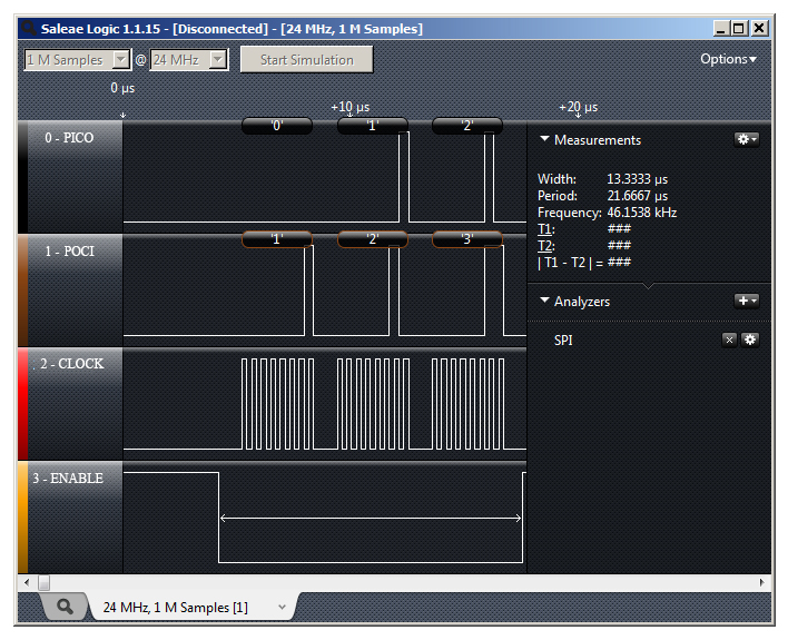
If things aren't working the way you think they should, a logic analyzer is a very helpful tool. Smart analyzers like the Saleae USB Logic Analyzer can even decode the data bytes for a display or logging.
Advantages of SPI:
It's faster than asynchronous serial
The receive hardware can be a simple shift register
It supports multiple peripherals
Disadvantages of SPI:
It requires more signal lines (wires) than other communications methods
The communications must be well-defined in advance (you can't send random amounts of data whenever you want)
The controller must control all communications (peripherals can't talk directly to each other)
It usually requires separate CS lines to each peripheral, which can be problematic if numerous peripherals are needed.
Further Reading
Check out the Wikipedia page on SPI, which includes lots of good information on SPI and other synchronous interfaces.
This page presents a more correct way to set up an SPI network amongst your embedded devices, particularly for use with an Arduino microcontroller.
A number of SparkFun products have SPI interfaces. For example, the Bar Graph Breakout kit has an easy-to-use SPI interface that you can use to turn any of 30 LEDs on or off.
Other communication options:
Serial Communication
Analog to Digital Conversion
I2C
AST-CAN485 Hookup Guide
Now that you’re a pro on SPI, here are some other tutorials to practice your new skills: