AST-CAN485 Hookup Guide
Introduction
The AST-CAN485 is a miniature Arduino in the compact form factor of the Arduino Pro Mini. In addition to all the usual features it has on-board CAN and RS485 ports enabling quick and easy interfacing to a multitude of industrial devices. The CAN485 bridges the gap between the maker and industrial spaces.
The CAN485 builds on the popular Arduino platform. It is pin-compatible with the Arduino Pro Mini, giving it a small form factor ideal for embedding in projects. It supports the Arduino IDE, the Arduino core libraries, and can be installed using the boards manager. Libraries are provided to support the CAN and RS485 ports. On-board CAN and RS485 transceivers allow for out of the box interfacing to any CAN or RS485 based network. CAN and RS485 form the backbone of many communications protocols with applications in automation, industrial systems, building management, automotive systems, OBDII, and many more.
Suggested Reading
If you aren’t familiar with the following concepts, we recommend checking out these tutorials before continuing.
How to Solder: Through-Hole Soldering
Serial Communication
What is an Arduino?
Installing Arduino IDE
Logic Levels
Resistors
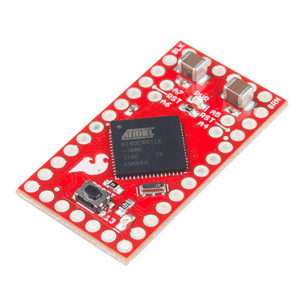
Hardware Overview
The CAN485 adopts the same tiny form factor as the Pro Mini measuring about 34.65mm x 19.20mm, making it easily embeddable in applications where space is limited. The pin layout is the same as the Arduino Pro Mini. This makes it pin compatible with existing Pro Mini shields and applications. An additional row of pins below the RESET button on the fourth side contains the CAN and RS485 ports.
 |
 |
| AST-CAN485 Dimensions | Arduino Pro Mini Dimensions |
Pinout
While the pin assignments are similar to the Arduino Pro Mini, there are some differences in their functions. Care should be taken when using shields designed for the Pro Mini with the CAN485. The graphical datasheet gives more details about the pins and their functions.

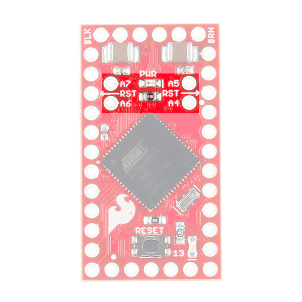
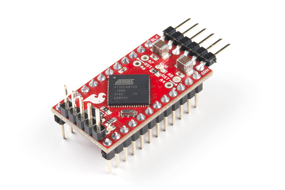
The CAN485 is based on the Atmel AT90CAN128 processor. The processor runs at 16MHz, has 128KB or Flash, 4KB of SRAM and features a hardware CAN controller. The CAN485 breaks out commonly used communications ports and pin functions including: I2C, SPI, UARTs, 8 analog inputs, and 6 interrupt enabled pins.
More information can be found on the AT90CAN128 datasheet and AST-CAN485 schematic.
| Target's External Power | CAN485 | AVR Programmer |
|---|---|---|
| D1 (TX0) on FTDI Header | MISO | |
| D13 (SCK) | SCK | |
| RST | RST | |
| 5V | 5V | 5V |
| D0 (RXI) on FTDI Header | MOSI | |
| GND | GND | GND |
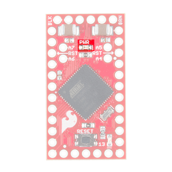
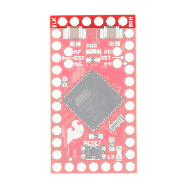
Power
There are several ways that the CAN485 can be powered.

The CAN485 has an on-board regulator allowing for an unregulated input voltage to be supplied on the RAW pin. The allowable input voltage range is 7-16V, however 7-12V is recommended.
A regulated 5V supply may also be supplied directly to Vcc. Supplied voltage must be in the range 4.5V to 5.5V. Power can also be supplied to the FTDI header by a FTDI breakout.
Once the board is powered, the PWR led will light up.
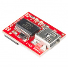
FTDI Programming Header
Like the Pro Mini, the CAN485 has no on-board USB connection. An external FTDI breakout board is required to program the board or connect it to a PC.
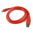
To connect, you would need a 5V FTDI, header pins to connect, and a mini-B USB cable.

CAN Port
The CAN controller is hardware accelerated, allowing for high speed CAN communication with minimal processor overhead. The on-board CAN transceiver means the CAN485 can be directly connected to a CAN network with no additional electronics.
 |
 |
| AST-CAN485 Front Side: CAN Port | AST-CAN485 Front Side: CAN IC and Port |
Connecting to a CAN Network
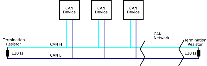
The image below shows a typical connection between the CAN485 and a CAN network. The network consists of two lines (CANH and CANL). Multiple devices may be connected in parallel on these lines. The bus must be terminated at each end with termination resistor (typically 100Ω to 120Ω).

For more information, check out the Introduction to CAN Bus.
RS485 Port
Similar to the CAN port, the CAN485 features an on-board RS485 transceiver which allows for simple connection to any RS485 network. While UART1 is consumed by the RS485 port, it is also broken out on pins 22 and 23 if the user would rather use it as a serial port.
 |
 |
| AST-CAN485 Front Side: RS485 Port | AST-CAN485 Back Side: RS485 IC and Port |
Connecting to a RS485 network
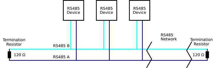
The image below shows a typical connection between the CAN485 and a RS485 network. The network consists of two lines (A and B), devices are connected in parallel on these lines. The bus must be terminated at each end with a termination resistor (typically 100Ω to 120Ω)
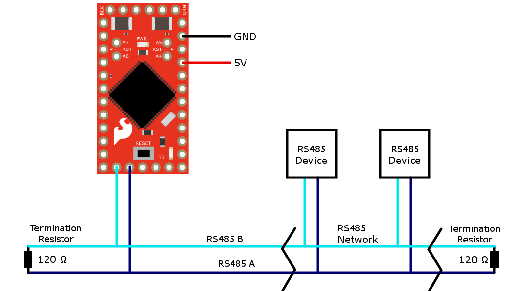
For more information, check out the Introduction to RS485.
JTAG
The JTAG programming and debugging interface is broken out on pins 18-21. This allows for more advanced debugging with Atmel Studio users.
One important implication is that in order to use these pins for I/O, the JTAG interface must be disabled. This can be done by adding a small bit of code to the setup() function.
Software Serial w/ AltSoftSerial
Unfortunately, the AT90CAN128 chip's pins do not support change interrupts. Therefore, the Arduino SoftwareSerial library is not supported. The AltSoftSerial library may be used as an alternative.
There are some limitations associated with the AltSoftSerial library. It uses a Timer resource on the microprocessor. Only one Timer is available so only one AltSoftSerial port is available and it is fixed on pins 5 and 9. AST modified the standard AltSoftSerial library to support the CAN485. The library is available on AST's GitHub.
Hardware Hookup
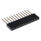
The CAN485 does not come with headers soldered on. We’ve left it up to you to solder on the headers or wires to the board for your project. Options include stackable headers, bent headers, or soldering wires directly to the pin pads.

If you are new to soldering, check out the tutorial on through hole soldering. You will need a soldering iron, solder, and general soldering accessories.

Hakko FX888D Soldering Station
TOL-11704A standard configuration for prototyping is to have the pins on the side facing down to allow for easy breadboarding while having the FTDI facing out and communications pins facing up for access via jumper cables.
Software Installation
Note: You will need to upgrade if you are using a version older than 1.6.3. This example assumes you are using the latest version of the Arduino IDE on your desktop. If this is your first time using Arduino, please review our tutorial on installing the Arduino IDE.
The next step is to install the CAN485 board into the Arduino IDE. There are two methods of installation. The first is by using the Arduino Boards Manager, this is the preferred method. The second method is to manually copy files from the GitHub repository.
Board Installation Using the Boards Manager
Using the Arduino IDE's boards manager is the preferred installation method.
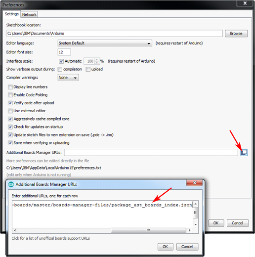
Open the preferences window (File > Preferences) in the Arduino IDE. Copy the following URL and add it to the list of boards manager URLs:
https://raw.githubusercontent.com/Atlantis-Specialist-Technologies/Arduino-Boards-Packages/master/package_ast_boards_index.json
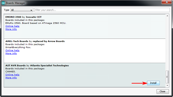
Open the boards manager (Tools > Board > Boards Manager...):
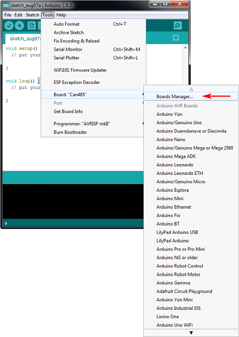
Scroll to AST AVR Boards and click on the Install button:
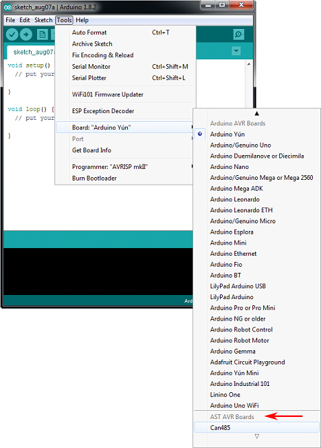
The AST AVR boards will now be available under the boards menu. Select the Can485 when uploading to the development board.
Manual Board Installation
To manually install the AST AVR Board add-on:
- Download the CAN485 repository from GitHub.
- Unzip the folder.
- Copy the ast folder to **…\MyDocuments\Arduino\hardware** .
- The directory structure should be: …\MyDocuments\Arduino\hardware\ast .
Manual Library Installation
Note: If you have not previously installed an Arduino library, please check out our installation guide.
To manually install the CAN library:
- Download the AST_CAN_Arduino_Library repository from GitHub.
- Unzip the AST_CAN_Arduino_Library-master.zip folder.
- Click on the ...\AST_CAN_Arduino_Library-master folder.
- Move the AST_CAN_Arduino_Library-master folder into the Arduino libraries folder: **...\MyDocuments\Arduino\libraries** .
- (Create the libraries folder if it does not exist)
- The final directory structure should be: ...\MyDocuments\Arduino\libraries\AST_CAN_Arduino_Library-master .
To manually install the RS485 library:
- Download the AST_RS485_Arduino_Library repository from GitHub.
- Unzip the AST_RS485_Arduino_Library-master.zip folder.
- Click on the ...\AST_RS485_Arduino_Library-master folder.
- Move the AST_RS485_Arduino_Library folder into the Arduino libraries folder: **...\MyDocuments\Arduino\libraries**
- (Create the libraries folder if it does not exist)
- The final directory structure should be: ...\MyDocuments\Arduino\libraries\AST_RS485_Arduino_Library-master .
To manually install the AST AltSoftSerial library:
- Download the RS485 library repository from GitHub.
- Unzip the AltSoftSerial-master.zip folder.
- Click on the ...\AltSoftSerial-master folder.
- Unzip into the Arduino libraries folder: **...\MyDocuments\Arduino\libraries**
- (Create the libraries folder if it does not exist)
- The final directory structure should be: ...\MyDocuments\Arduino\libraries\AltSoftSerial-master .
Multiple libraries were found for "AltSoftSerial.h"

   Used: ...\Documents\Arduino\libraries\AltSoftSerial

   Not used: ...\Documents\Arduino\libraries\AST_AltSoftSerial_Arduino_Library

exit status 1

Error compiling for board Can485.
One quick fix is to move the PaulStoffregen's "AltSoftSerial" out of the Arduino libraries folder and only use AST's "AltSoftSerial" library when compiling code for the AST-CAN485. This will avoid conflicts with multiple libraries using the same name.
Uploading Code
Connect the FTDI programming cable to the FTDI header as shown:
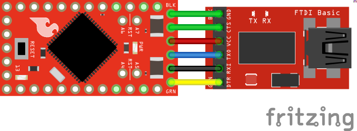
Open the Arduino IDE and select the CAN485 board in the tools menu. Ensure that the correct COM port is being used. Upload the Blink example (Examples>01.Basics>Blink). You should see the built-in LED connected to pin 13 flash.
Introduction to CAN Bus
The Controller Area Network (CAN) bus is a communications standard with its origins in the automotive industry. It has several built in features that make it robust and noise tolerant. It is a message based protocol that is able to support multiple nodes. Speeds up to 1Mbps are supported over distances less than 40m while longer distances are possible at lower speeds (500m at 125Kbps). CAN bus also features an arbitration method which automatically prioritizes messages and resolves packet collisions.
CAN is used as a field bus in industrial applications and comprises the lower layer on top of which many higher-layer protocols are based. CANopen and DeviceNet are common higher layer protocols based on CAN bus and used in industrial automation. CAN bus is also used in the OBDII vehicle diagnostics standard which is mandatory on modern cars in the US and EU.
Signal Description
A CAN bus consists of two signals (CAN H and CAN L) and terminated at each end with a termination resistor (typically 100Ω to 120Ω). For high speeds, it is recommended to to have a 120Ω termination resistor. These lines are usually wound into a twisted pair.
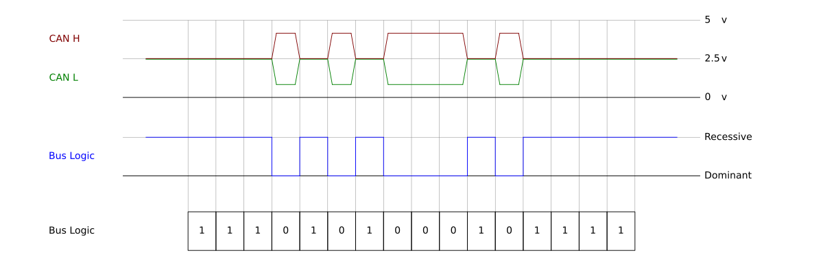
The bus has a recessive state (Logic 1) and a dominant state (logic 0). The bus needs to be actively driven to the dominant state by one of the nodes. If it is not driven to the dominant state by any of the nodes, the bus will return to the recessive state. This dominant and recessive behavior means that if two nodes transmit at the same time, the dominant bits will take preference. A method of arbitration takes advantage of this behavior to resolve packet collisions.
A CAN transceiver is necessary to translate between the line states and the logical states used by a microprocessor.
Network Structure
Multiple nodes may be connected in parallel. The lines must be terminated on each end with a termination resistor (typically 100Ω to 120Ω). For high speed CAN bus, the network below included a termination resistor of 120Ω at each end.
Packet Structure
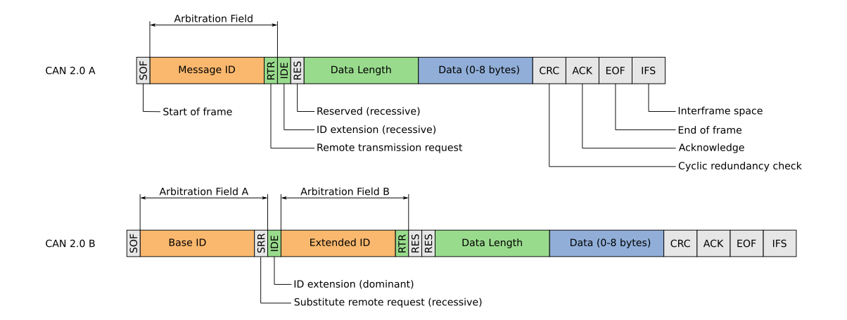
CAN messages have a standard format consisting of a message ID, a data length field, a data frame, a CRC and other control bits. Being a message based protocol, there are no node addresses, instead there is a message ID. Data is associated with an ID as opposed to a device and one node may transmit using several message IDs. This behavior can be very useful. For example, a node can report motor speed, position and acceleration on three different message IDs, allowing for easy identification of parameters by any receiving nodes.
Message IDs should be unique. If two nodes attempt to send a message with the same ID at the same time, it will cause an error. The message ID is also used in the arbitration process to determine which message has priority when two nodes attempt to transmit at the same time.
There are two standard formats for CAN packets, the base format (CAN2.0A) and the extended format (CAN2.0B). The extended format features a 29-bit ID while the base format features an 11-bit ID. The extended format is backwards compatible, allowing for both formats to be used on any CAN network.
Arbitration
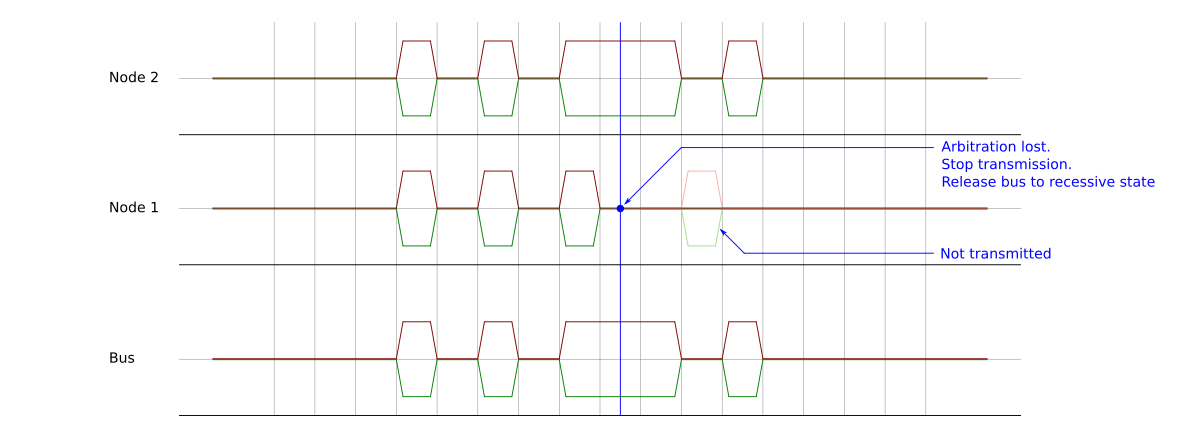
When two nodes attempt to transmit at the same time an arbitration process determines which one takes preference. While transmitting, each node reads the bus state as well. If a node detects that one of its recessive bits has been driven dominant by another node, then it stops transmitting. This results in lower IDs taking precedence over higher IDs. If a node looses arbitration, it will attempt to resend the message once the current transmission is complete. This behavior results in automatic prioritization and collision resolution.
Example: Simple CAN Network
In this example, a simple two node CAN bus network is constructed. One node transmits a message, the other receives it and passes it on over the serial port to a PC.
Required Materials
The following materials are required for this example. You may not need everything though depending on what you have. Add it to your cart, read through the guide, and adjust the cart as necessary.
- 2x CAN485
- 2x 120Ω Resistors*
- FTDI
- USB Cable
- Breadboard, Jumper Wires, etc.
Hardware Hookup
Construct the network as shown.

Upload Code
Ensure that the CAN485 boards and CAN library have been installed. The example code is installed with the CAN library. It is available in the Arduino IDE under the examples menu.

Upload the transmitter example code to the transmitter node. Then upload the receiver example code to the receiver node.
What You Should See
The transmitter node will send a message every 500ms. The receiver node will receive it and pass it on to the PC over the serial port. Open the serial port on the PC using the Arduino Serial Monitor (or your favorite serial terminal) and select 1000000 (1MBaud).
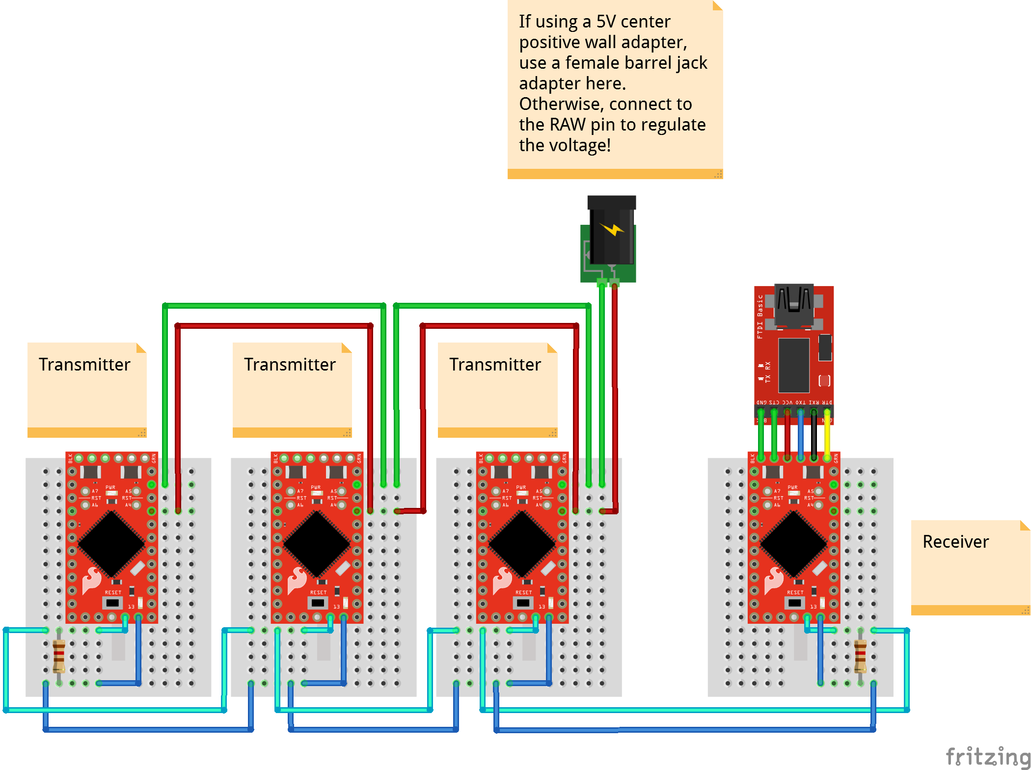
Example: Multi-Node CAN Network
In this example a larger CAN network is constructed. Multiple nodes send messages and one node relays them to a PC over a serial port.
Required Materials
The following materials are required for this example. You may not need everything though depending on what you have. Add it to your cart, read through the guide, and adjust the cart as necessary.
- 3x or More CAN485
- 2x 120Ω Resistors*
- FTDI
- USB Cable
- Breadboard, Jumper Wires, etc
- 1x External Power Supply**
- 1x DC Barrel Jack Adapter Female**
Hardware Hookup
Construct the network as shown.
Upload Code
Ensure that the CAN485 boards and CAN library have been installed. The example code is installed with the CAN library. It is available in the Arduino IDE under the examples menu.
Upload the transmitter example code to the each of the transmitter nodes. Make sure to change the message IDs (MESSAGE_ID) to unique values for each node.
Then upload the receiver example code to the receiver node.
What You Should See
The transmitter nodes will each send a message every 500ms. The receiver node will receive it and pass it on to the PC over the serial port. Open the serial port on the PC using the Arduino Serial Monitor (or your favorite serial terminal) and select 1000000 (1MBaud).
Introduction to RS485
RS485 is a standard used extensively in serial communications systems. Only the electrical interface is defined by RS485. No specific communication protocol is specified by the standard; instead it forms the physical layer for many different protocols. For example a serial port may run over a RS485 physical link.
RS485 uses differential signaling over a twisted pair making it resilient to noise. Multiple nodes are also supported, the number of which is usually determined by the protocol in use. Distances up to 1200m and transmission speeds up to 10Mb are possible. However, there is a trade-off between distance and speed. For example, a 50m cable can run at 2Mbps.
RS485 is one of the commonly used physical layers. Applications include industrial systems, computing, automotive, and building management. Modbus and Profibus are two common industrial protocols that make use of RS485.
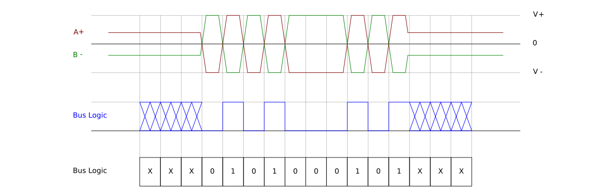
Signal Description
The interface consists of two lines with signals A and B. When the bus is idle, both lines float. When in operation one node acts as a controller and takes control of the bus, driving the two lines to the appropriate voltages. The other nodes act as peripherals and receive the data being transmitted. The lines are driven to opposing polarities; if A is positive, B is negative. By inverting the signals, logic levels of 0 or 1 are possible.
Network Structure
Multiple nodes may be connected in parallel. The lines must be terminated on each end with a termination resistor (typically 100Ω to 120Ω).
Example: Simple RS485 Network
In this example, a simple two node RS485 bus network is constructed. One node transmits a message every 500ms. The other receives it and passes it on over the serial port to a PC.
Required Materials
The following materials are required for this example. You may not need everything though depending on what you have. Add it to your cart, read through the guide, and adjust the cart as necessary.
- 2x CAN485
- FTDI
- USB Cable
- 2x 120Ω Resistors*
- Breadboard, Jumper Wires, etc
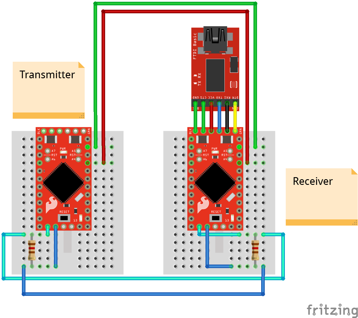
Hardware Hookup
Construct the network as shown.
Upload Code
Ensure that the CAN485 boards and RS485 library have been installed. The example code is installed with the RS485 library. It is available in the Arduino IDE under the examples menu.
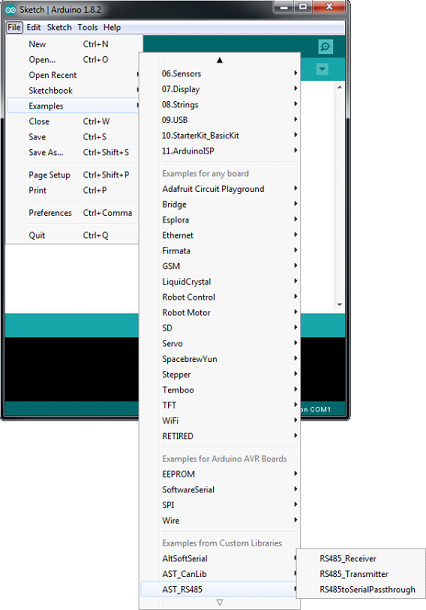
Upload the receiver example code to the receiver node. Then upload the transmitter example code to the transmitter node.
What You Should See
The transmitter node will send a message every 500ms. The receiver node will receive it and pass it on to the PC over the serial port. Open the serial port on the PC using the Arduino Serial Monitor (or your favorite serial terminal) at 115200baud.
Companion Boards
If you are looking to control 24V inputs and outputs using the CAN485, check out the I/O shield (24V) for wired connections.
AST-CAN485 I/O Shield (24V) Hookup Guide
If you need to control RS485 or CAN devices remotely, check out the WiFi shield..
AST-CAN485 WiFi Shield Hookup Guide
Resources and Going Further
Now that you've successfully got your AST-CAN485 Development Board up and running, it's time to incorporate it into your own project!
For more information, check out the resources below:
- Schematic
- Eagle Files
- AST GitHub Repo
- Datasheets
- CAN Bus
- RS485
- Product Showcase: SparkFun AST-CAN485 Dev Board
Need some inspiration for your next project? Check out some of these related tutorials:
OBD II UART Hookup Guide
CAN-BUS Shield Hookup Guide
Getting Started with OBD-II
Or dig in further with According to Pete for more information about RS485.