OBD II UART Hookup Guide
 Toni_K
 Introduction
Have you ever had an infamous 'check engine light'? Did you wish you could just check the error code yourself and not deal with going to a mechanic? With the OBD-II UART, your wishing can become a reality. The OBD-II UART allows you to connect your car to a computer, embedded microcontrollers, or single board computers such as the Raspberry Pi or Beaglebone Black.

SparkFun Car Diagnostics Kit
RTL-10769This guide will show you:
- What hardware is included on the OBD-II UART
- The basics of OBD-II commands
- How to hook this up over FTDI directly with your computer
- How to hook this up to an Arduino and display information to an LCD
Required Materials
To follow along with the tutorial, you will need the following parts.
Required Tools
- Soldering iron
- Solder
- A laptop
Suggested Reading
This tutorial does expect the user to have experience with basic electronics and serial communication. If you are unfamiliar with these concepts or need a refresher, check out these other tutorials.
How to Solder: Through-Hole Soldering
Serial Communication
Working with Wire
What is an Arduino?
Hexadecimal
Getting Started with OBD-II
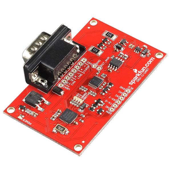
Board Overview
On-Board Diagnostics, Second Generation (OBD-II) is a set of standards for implementing a computer based system to control emissions from vehicles. It was first introduced in the United States in 1994, and became a requirement on all 1996 and newer US vehicles. Other countries, including Canada, parts of the European Union, Japan, Australia, and Brazil adopted similar legislation. A large portion of the modern vehicle fleet supports OBD-II or one of its regional flavors.
Among other things, OBD-II requires that each compliant vehicle be equipped with a standard diagnostic connector (DLC) and describes a standard way of communicating with the vehicle’s computer, also known as the ECU (Electronic Control Unit). A wealth of information can be obtained by tapping into the OBD bus, including the status of the malfunction indicator light (MIL), diagnostic trouble codes (DTCs), inspection and maintenance (I/M) information, freeze frames, VIN, hundreds of real-time parameters, and more. You can read more about the OBD-II protocol here.
STN1110 is an OBD to UART interpreter that can be used to convert messages between any of the OBD-II protocols currently in use, and UART. It is fully compatible with the de facto industry standard ELM327 command set. Based on a 16-bit processor core, the STN1110 offers more features and better performance than any other ELM327 compatible IC. ScanTool has some great resources for the STN1110 available on their website, including:
Board Schematic
The OBD-II UART board has both the STN1110 and the MCP2551 chips populated on it, allowing the user to access both CAN and OBD-II protocols. The schematic can be viewed/downloaded here.
The STN1110 is the main controller chip on the board. This communicates with the CAN, ISO and J1850 transceivers. Voltage on the board is regulated to both 5V and 3.3V for all of the components to function properly. The board is powered from the DB9 connector.
Board Pin Out
There are two different connection points on the board. The first, on the outside edge of the board, is a 6-pin connector that is compatible with an FTDI board. However, only the TX, RX and GND pins are connected on this header, to allow for UART communication.
There is a second 8-pin header close to the DB9 connector. This allows the user to tap into the VBAT line, the CAN bus, the LINE bus and the J1858 bus, along with the common ground pin.
Now that we now about the board itself, let's move on to hooking it up!
First Communcation
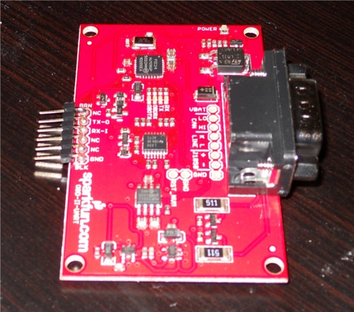
Soldering Headers
To create a solid electrical connection with any other components (such as an Arduino or an FTDI Basic), you need to solder headers to the board. For use with the FTDI Basic, it is easiest to solder male headers into the 6-pin header row at the edge of the board. Once you have this done, your board should look similar to this.
Connecting to a Vehicle OBD Port
You will need to connect the OBD-II board to the OBD port on your vehicle. Depending on the make and model of your car, the port location may vary. Consult your owner's maunal if you cannot locate the port.
Once you have located your OBD port, you will need to hook up the OBD-to-DB9 cable to the vehicle's port.
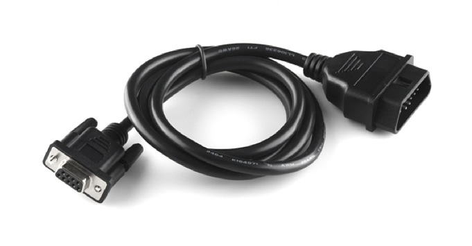
The mating end of the cable tends to be a very tight fit and require a bit of force to get it sitting securely, so it's usually easier to start hooking everything together between the car and the cable. Once you get the car and the cable connected, then connect the DB9 end of the cable to the OBD-II board.
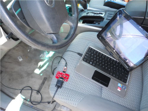
Connecting over a Serial Port
Once you have your headers attached to your board, and you've connected to your vehicle using the OBD-DB9 cable, you can start communicating withe OBD-II board over through a serial port using an FTDI Basic breakout board. The FTDI pinout matches with the 6 pin header on the OBD-II board, but only connects TX, RX and GND. Connect the FTDI board to the computer via a mini-USB cable, and open up a serial terminal on your computer. Configure the serial connection to 9600 bps, 8 data bits, 1 stop bit and no parity.
Once you have your serial terminal set up, you will communicate with the OBD-II board by using AT commands. These commands always start with "AT". The OBD-II board is case-insensitive, so don't stress about only using capital letters. After sending "AT", the next letters sent to the board will be the commands that should be executed by the board. You can find a list of all of the available AT commands here.
To start communicating with the board, type "ATZ" into your terminal window and hit "enter". This will send the command to reset the board. You should see some LEDs flash on your board and then see the start-up prompt in the terminal window.
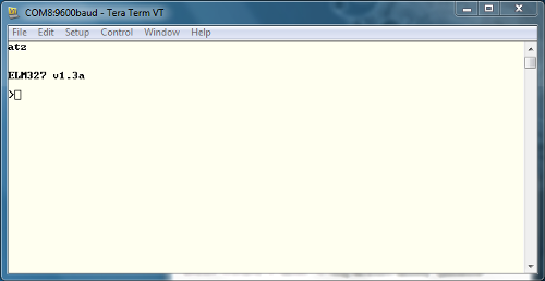
If you receive back any garbled characters, double check that you have the correct serial port settings in your terminal.
Once you have proper communcation with your board set up, try reading the OBD-II UART system voltage. Type "ATRV" into the terminal window and hit enter. The board should then return the system voltage to you.
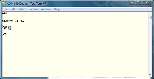
This voltage reading should match your vehicle's battery voltage.
To read additional OBD parapters for the vehicle, the OBD-II board must first be configured to the correct OBD protocol. There are several different OBD protocols, so it can be confusing attempting to find the correct one. However, like all things awesome, this OBD-II board automatically detects the protocol. To use this auto-detect feature, the vehicle's ignition must be in the 'On' position. The vehicle doesn't necessarily need to be running however. Once the ignition is on, send the command "ATSP0" (that's a trailing zero). The board will then reply with "OK" once the proper protocol has been detected.
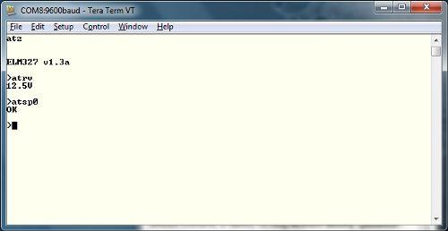
Once you have the proper protocol detected on your board, you can start sending OBD commands to the board.
OBD Commands
OBD Commands
The OBD commands are made up of hexadecimal codes written in ASCII characters. Generally, these commands contain 2 or more pairs of hexadecimal numbers, however there are a few commands that only require one hex pair.
The first hex pair in the OBD command represents the OBD mode which should be used. Any following hex pairs after that represent the Parameter ID (PID) to be read from the specified mode. There are 10 OBD modes, but keep in mind that not all vehicles will use all 10 modes. You will want to check your particular vehicle's protocols to see what OBD modes and parameter IDs are supported.
| Mode Number | Mode Description |
| 01 | Current Data |
| 02 | Freeze Frame Data |
| 03 | Diagnostic Trouble Codes |
| 04 | Clear Trouble Code |
| 05 | Test Results/Oxygen Sensors |
| 06 | Test Results/Non-Continuous Testing |
| 07 | Show Pending Trouble Codes |
| 08 | Special Control Mode |
| 09 | Request Vehicle Information |
| 0A | Request Permanent Trouble Codes |
You can read up more on the OBD PIDs functionality on Wikipedia. Some vehicle manufacturers also use their own proprietary parameters, so keep in mind that these may not be a comprehensive list for your car. Again, the ELM327 AT Commands datasheet is another good resource to check out.
Possibly the most important PID is 00. This works on any vehicle that supports OBD and gives a list of other PIDs which the car supports. In your terminal window (you do still have that open, right?!), type "0100" and hit "enter". This command translates to "In mode 01, what PIDs are supported?"
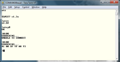
There is a general structure that all OBD responses have in common. The first response byte (in this case 0x41) lists the mode that was requested in the command. Thus the board sends 0x40 + 0x01. The second byte is the parameter that was requested, so in our case, 0x00. Any following bytes are the responses to the command. In this case, the bytes 0xBF, 0x9F, 0xA8 and 0x93 are the PIDs that are supported by the vehicle.
One other commonly supported parameter is the 'Read Engine RPM'. Issue command "010C' and press enter. Keep in mind that the board will respond with a value listed in hex.
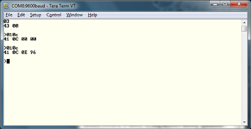
The response structure is the same as before. 0x41 to state the board is in mode 01, followed by 0x0C to show that the board is looking at the RPM parameter. The returned value of 0x0E 0x96 can then be converted into a decimal value of 3734. This is actually 4 times the actual RPM, as this value is listed in quarters of RPM. Once the value is divided by 4, we have an idiling RPM of 933.
Check out the datasheet for the ELM327 for more PIDs to try out. Now let's look at hooking the OBD-II board up to an Arduino.
Connecting to an Arduino
Connecting to an Arduino
Besides connecting directly to your computer with the OBD-II board, you can also run the data through an Arduino board and display the information on an LCD for embedding a project. For this section, you will need an Arduino Uno (or another 5V Arduino board), jumper wires, and a serial LCD.
You will only need to make 6 connections between all 3 devices to get this set up. Use the diagram and the chart below to properly wire everything.
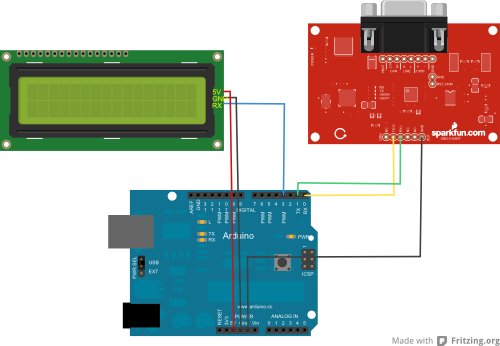
| Arduino Pin | Serial LCD Pin | OBD-II-UART Pin |
| GND | GND | GND |
| 5V | 5V | None |
| D3 | Rx | None |
| D0(Rx) | None | Tx-O |
| D1(Tx) | None | Rx-I |
You will want to download the sketch file here, or you can find the most up to date version of the code on GitHub. Keep in mind when you upload this to your board, you will want to disconnect the OBD-II board RX line from the Arduino TX-0, to prevent issues during code upload, such as bricking the OBD-II board.
Another thing to note about this set up is that the Arduino is not powered off of the OBD-II board. Therefore, you will need to either use USB power from your laptop to power the Arduino, or use a battery supply suck as a 9V battery and 9V barrel jack adapter.
Understanding the Sketch
This example sketch is very simple. The Arduino simply communicates with the OBD-II board and then sends the information received to the LCD screen. You will need to include the SoftwareSerial library in order to communicate with the LCD screen. Set the LCD TX/RX lines to pins 2 and 3 on the Arduino, and initialize the rest of your variables.
language:c
#include <SoftwareSerial.h>

//Create an instance of the new soft serial library to control the serial LCD
//Note, digital pin 3 of the Arduino should be connected to Rx of the serial LCD.

SoftwareSerial lcd(2,3);

//This is a character buffer that will store the data from the serial port
char rxData[20];
char rxIndex=0;

//Variables to hold the speed and RPM data.
int vehicleSpeed=0;
int vehicleRPM=0;
In the set up loop, the serial port for the LCD as well as the serial port for talking to the OBD-II board are both initialized at 9600 bps. The screen is then cleared, and the variable names of Speed and RPM are printed on the first and second rows respectively. As we did before, the OBD-II board is then reset.
language:c
void setup(){
  //Both the Serial LCD and the OBD-II-UART use 9600 bps.
  lcd.begin(9600);
  Serial.begin(9600);

  //Clear the old data from the LCD.
  lcd.write(254);
  lcd.write(1);

  //Put the speed header on the first row.
  lcd.print("Speed: ");
  lcd.write(254);
  //Put the RPM header on the second row.
  lcd.write(128+64);
  lcd.print("RPM: ");

  //Wait for a little while before sending the reset command to the OBD-II-UART
  delay(1500);
  //Reset the OBD-II-UART
  Serial.println("ATZ");
  //Wait for a bit before starting to send commands after the reset.
  delay(2000);

  //Delete any data that may be in the serial port before we begin.
  Serial.flush();
}
The main loop of the code simply sets the cursor locations, clears out any old data on the LCD screen, receives the data from the OBD-II board, tranlates it to an integer and prints the vehicle speed and RPM to the screen.
language:c
void loop(){
  //Delete any data that may be in the serial port before we begin.
  Serial.flush();
  //Set the cursor in the position where we want the speed data.
  lcd.write(254);
  lcd.write(128+8);
  //Clear out the old speed data, and reset the cursor position.
  lcd.print("        ");
  lcd.write(254);
  lcd.write(128+8);
  //Query the OBD-II-UART for the Vehicle Speed
  Serial.println("010D");
  //Get the response from the OBD-II-UART board. We get two responses
  //because the OBD-II-UART echoes the command that is sent.
  //We want the data in the second response.
  getResponse();
  getResponse();
  //Convert the string data to an integer
  vehicleSpeed = strtol(&rxData[6],0,16);
  //Print the speed data to the lcd
  lcd.print(vehicleSpeed);
  lcd.print(" km/h");
  delay(100);

  //Delete any data that may be left over in the serial port.
  Serial.flush();
  //Move the serial cursor to the position where we want the RPM data.
  lcd.write(254);
  lcd.write(128 + 69);
  //Clear the old RPM data, and then move the cursor position back.
  lcd.print("          ");
  lcd.write(254);
  lcd.write(128+69);

  //Query the OBD-II-UART for the Vehicle rpm
  Serial.println("010C");
  //Get the response from the OBD-II-UART board
  getResponse();
  getResponse();
  //Convert the string data to an integer
  //NOTE: RPM data is two bytes long, and delivered in 1/4 RPM from the OBD-II-UART
  vehicleRPM = ((strtol(&rxData[6],0,16)*256)+strtol(&rxData[9],0,16))/4;
  //Print the rpm data to the lcd
  lcd.print(vehicleRPM);

  //Give the OBD bus a rest
  delay(100);

}
Obsolete Code: Arduino has changed how the Serial.flush() function works. It no longer clears the input and output buffers; only the outgoing buffer is cleared.
Serial.available() and then read the buffer until it is empty.
The final section of code simply defines the functions to communicate with the OBD-II board. This saves any incoming characters to the serial buffer until a carriage return is received.The buffer index is set to 0 and the board then waits for the next string to come in.
language:c
/The getResponse function collects incoming data from the UART into the rxData buffer
// and only exits when a carriage return character is seen. Once the carriage return
// string is detected, the rxData buffer is null terminated (so we can treat it as a string)
// and the rxData index is reset to 0 so that the next string can be copied.
void getResponse(void){
  char inChar=0;
  //Keep reading characters until we get a carriage return
  while(inChar != '\r'){
    //If a character comes in on the serial port, we need to act on it.
    if(Serial.available() > 0){
      //Start by checking if we've received the end of message character ('\r').
      if(Serial.peek() == '\r'){
        //Clear the Serial buffer
        inChar=Serial.read();
        //Put the end of string character on our data string
        rxData[rxIndex]='\0';
        //Reset the buffer index so that the next character goes back at the beginning of the string.
        rxIndex=0;
      }
      //If we didn't get the end of message character, just add the new character to the string.
      else{
        //Get the new character from the Serial port.
        inChar = Serial.read();
        //Add the new character to the string, and increment the index variable.
        rxData[rxIndex++]=inChar;
      }
    }
  }
}
Resources and Going Further
Now that you've gotten the basics down for communicating with the OBD-II UART board, try modifying the example sketch to work with parameter IDs that are supported on your particular vehicle.
Software
You can also work with some free software available online, that prints the data out into cool graphs and meters for you without any programming required, other than using a serial port. Check out a current list of freeware for OBD boards below.
Now that you've successfully got your OBD II UART up and running, it's time to incorporate it into your own project!
For more information, check out the resources below:
- Schematic (PDF)
- Eagle Files (ZIP)
- Datasheet
- ELM327 Command Set (PDF)
- Compatible Software List
- GitHub Repo
- SparkFun According to Pete #56 How CAN BUS Works
- SparkFun According to Pete #57 How OBD2 Works
Or check out these videos from According to Pete's explanation of CAN BUS and OBD-II:
Need some inspiration for your next project? Check out some of these related tutorials: