CAN-BUS Shield Hookup Guide
 Toni_K, Member #399586
 Introduction
The CAN-Bus Shield provides your Arduino or Redboard with CAN-Bus capabilities and allows you to hack your vehicle!
This shield allows you to poll the ECU for information including coolant temperature, throttle position, vehicle speed, and engine rpms. You can also store this data or output it to a screen to make an in-dash project.
Materials Required
You will need the CAN-Bus Shield in order to follow along with this hookup guide.
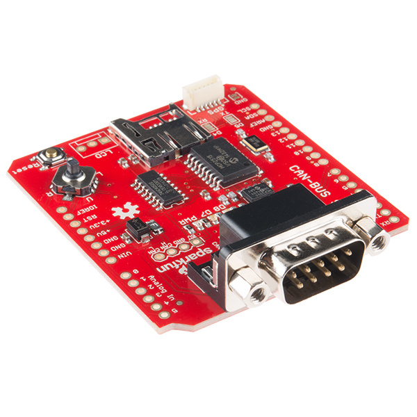
We also recommend you have access to the following materials.
Suggested Reading
If you aren't familiar with the following concepts, you may want to review these tutorials before attempting to work with the CAN-Bus Shield.
How to Solder: Through-Hole Soldering
Installing an Arduino Library
GPS Shield Hookup Guide
MicroSD Shield and SD Breakout Hookup Guide
Getting Started with OBD-II
Arduino Shields v2
Hardware Overview
There are several features to be aware of on the CAN-Bus Shield.
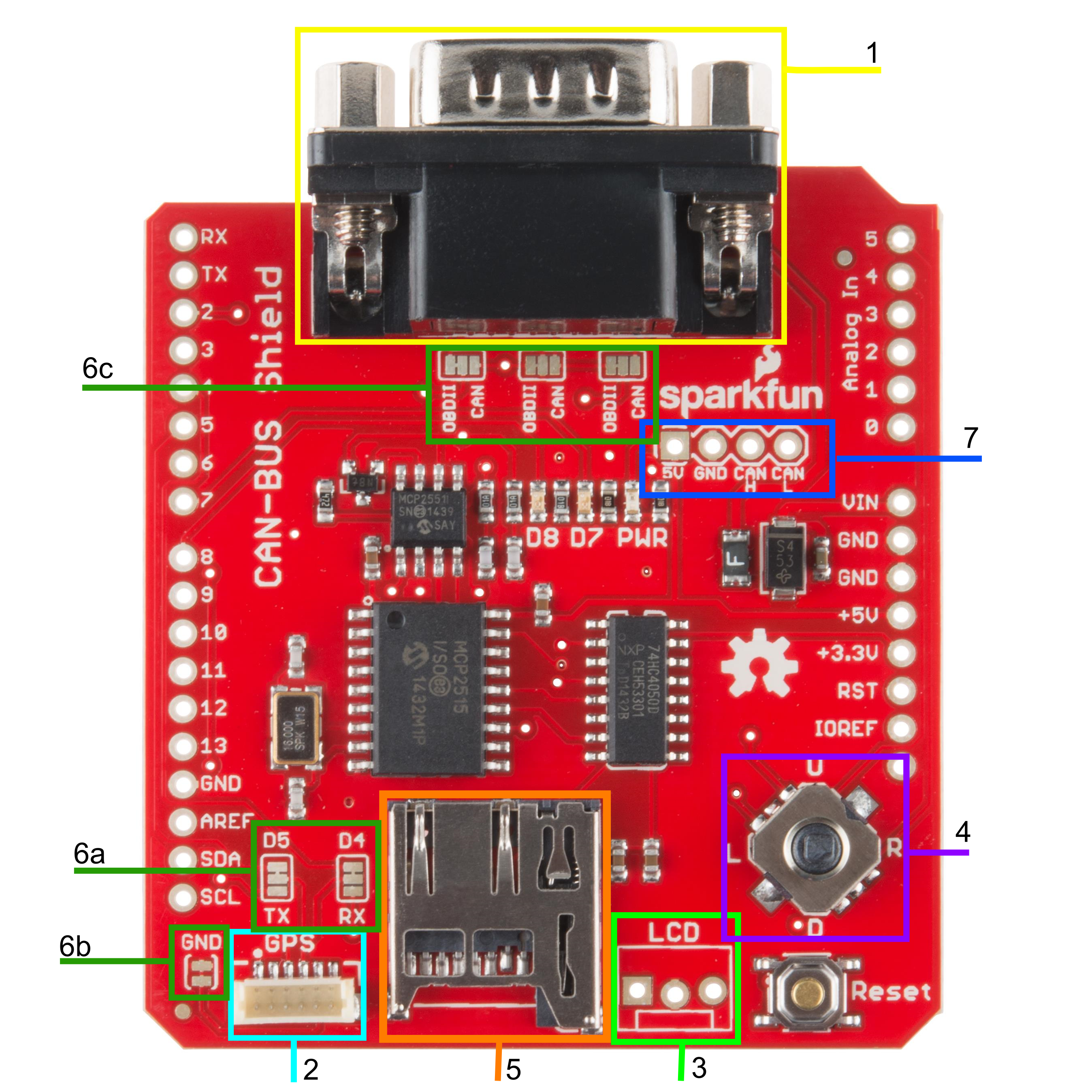
1. DB9 Connector
The primary hardware feature on this shield is the DB9 connector. This allows you to interface to OBD-II ports with a DB9 to OBD-II cable.
2. GPS Connector
The GPS connector on-board is a 6-pin, JST SH compatible connector. The board is designed to interface with either the EM-506 GPS Receiver, or the GP-735 GPS Receiver. The GND jumper allows the user to modify the GPS connector for units that do not have a GND connection on pin 5 of the connector.
3. LCD Connector
The LCD footprint on the shield is compatible with a male 3-pin JST connector and can interface with any of our serial LCD screens. The connection is designed for 5V LCDs, so don't accidentally plug in a 3.3V option! The pin order is 5V, GND, and RX/D6 when looking at the shield straight on.
4. JoyStick
The joystick included on the shield provides a basic user interface for controlling screen displays or selecting CAN scan settings. The connector gives 5 basic user options:
- Up
- Down
- Left
- Right
- Click selection
5. microSD Slot
This slot provides the user with the option of storing collected data onto a microSD card. Data collected can include user input on the joystick, CAN-Bus information collected, LCD outputs, or general I/O data.
6. Jumpers
There are six jumpers present on the CAN-Bus Shield.
6a. SJ1 and SJ2 - These two jumpers allow the user to select between UART and Software Serial for the GPS unit to communicate with the Arduino.
6b. SJ3 - This allows the user to separate pin 5 on the GPS connector from the
GNDline. This jumper comes closed by default.6c. SJ4, SJ5, and SJ6 - These three jumpers allow the user to select the DB9 pin configuration between OBD-II and CAN. The jumpers are defaulted to the OBD-II configuration that matches SparkFun's OBD-II to DB9 cable.
For reference, here are the configuration options showing which pins are selected on the DB9 connector for each setting.
| Bus Lines | CAN Pins | OBD-II Pins | Solder Jumper |
|---|---|---|---|
| CAN-H | Pin 7 | Pin 3 | SJ4 |
| CAN-L | Pin 2 | Pin 5 | SJ6 |
| GND | Pin 3 | Pin 2 | SJ5 |
7. CAN Pins
4 CAN lines are broken out to allow you direct access to the raw CAN data coming off of the DB9 connector. These pins are:
- 5V
- GND
- CAN H (CAN HIGH)
- CAN L (CAN LOW)
Again, this data is raw coming off of the CAN-Bus. It has not been filtered through the MCP2515 or the MCP2551 ICs.
Communication Methods
Because of all of the different hardware features on the shield, there are a couple different communication methods used.
SPI - The MCP2515 IC and the microSD slot both communicate with the Arduino via the SPI lines. The CAN
Chip Selectline is located onD10. The SDChip Selectline is connected toD9.Analog In - The joystick is connected to pins A1-A5 on the Arduino. Each direction of the joystick has its own analog input.
Software Serial/UART - The LCD and GPS both communicate over serial lines with the Arduino. The LCD's
RXline connects toD6. The GPS either connects via Software Serial toD4andD5, or to the UART port onD0andD1.
Hardware Hookup
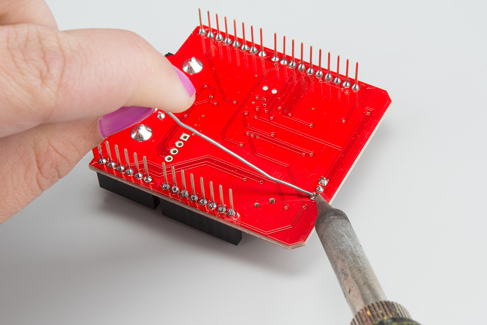
Solder Connectors
To get your CAN-Bus shield hooked up, solder on the Arduino Stackable Headers.
Once those are soldered, consider how you want to connect your LCD screen. You can use either male or female headers with 0.1" spacing, or the JST connector. Solder your interface choice onto the shield at this time as well.
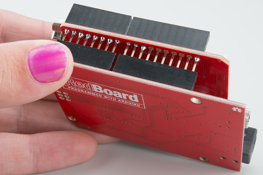
Connect the Brain!
In our case, the brain will be the RedBoard. Insert your shield into the RedBoard. Take your time and go slowly to prevent bending the header pins.
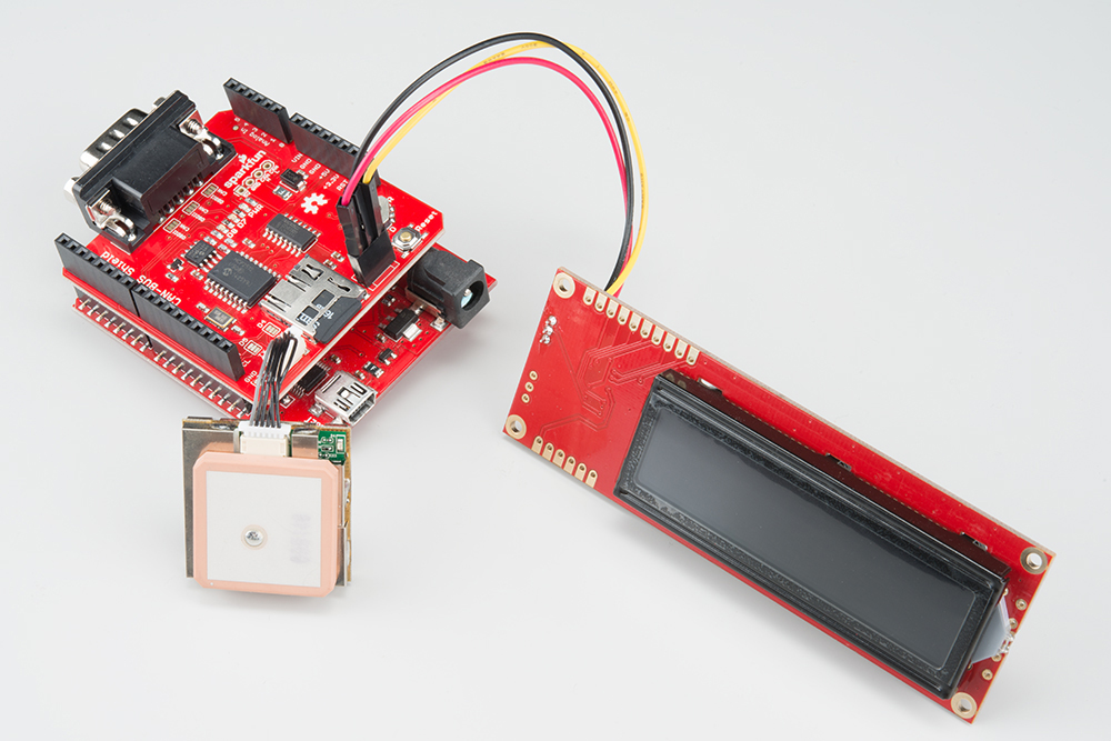
Connect the Extras
We recommend plugging in the GPS unit, LCD screen, and microSD card now. If you don't plan to use any of these features, you can skip this step.
If you're planning on putting your CAN-Bus/RedBoard combination into an enclosure, you may want to consider using an extension cable for the GPS unit. Enclosures can block the satellites from view and lead to spotty GPS functionality, so placing the GPS unit outside of any enclosures should alleviate those issues.
We also recommend connecting your LCD screen at this time. Your method of connecting the LCD screen will depend on what connector you soldered onto the shield previously. Looking the shield straight on, the connections are 5V, GND, and TX, if you are not using the JST connector.
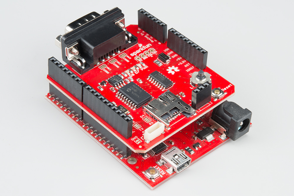
Make sure you use a formatted microSD card. Once all the extras are connected, your circuit should look like the following:
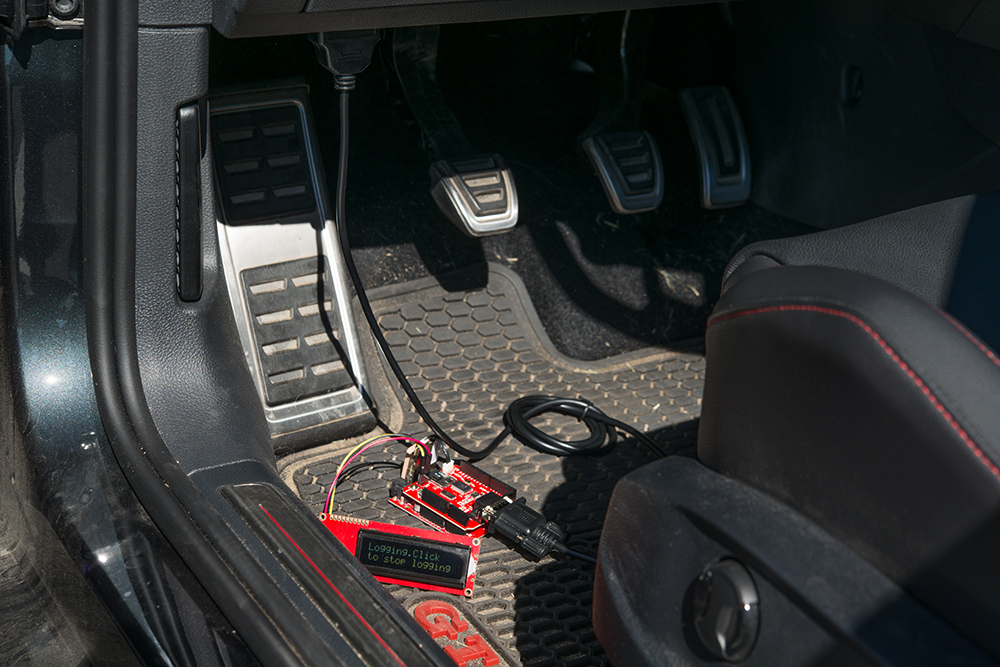
Connect to your CAN-enabled device
This can be a simulator or a vehicle. Plug the DB9 connector into the shield, and plug the DLC connector into the device to which you plan on talking. If your shield+Arduino turns on now, that's ok. The vehicle/simulator can power the board over the cable.
Final Circuit
Once everything is inserted, your circuit should look similar to the following:
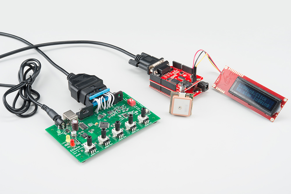
In this case, we show the circuit connected to a CAN simulator. However, you could instead have your circuit connected to a DLC in a CAN-enabled vehicle.
Arduino Library Installation
Note: This example assumes you are using the latest version of the Arduino IDE on your desktop. If this is your first time using Arduino, please review our tutorial on installing the Arduino IDE. If you have not previously installed an Arduino library, please check out our installation guide.
There's a really great library available for working with the CAN-Bus shield. You will need to download this and install it in your Arduino IDE. You can either search for it in the Arduino Library Manager or download the most recent version from the GitHub repository by downloading the library from the button below.
Example Code
There are several different example sketches included in the library, each with different functionality.
SparkFun_CAN_Demo - This sketch allows you test the CAN functionality of the board by itself.
SparkFun_ECU_Demo - This sketch runs all hardware on the shield together, and logs CAN data and GPS data to the SD card, while outputting data over the serial LCD. You will need to instally the TinyGPS library and the SD library for this to work.
SparkFun_GPS_Demo- This sketch runs through using the GPS module. You will need to instally the TinyGPS library for this to work.
SparkFun_Joystick_Demo - This quick sketch allows you to test the functionality of the on board joystick.
SparkFun_SD_Demo - This sketch allows you to verify and test functionality of the microSD socket on board. You will need to install the SD library for this to work.
SparkFun_SerialLCD_Demo - A quick sketch to make sure your serial LCD screen is functioning properly.
CAN_Read_Demo - A very stripped down sketch to read any and all data coming out of the CAN bus.
CAN_Write_Demo - A basic demo for writing to the CAN bus.
For our example, we are going to run through the ECU_Demo sketch, but feel free to use or modify the other sketches. If you decided to not plug in the microSD card, GPS unit and LCD screen, you should instead run the CAN_Demo.
ECU_Demo
This sketch shows off the basic functionality of each part of the shield. Once you've installed the library, open up Arduino and upload this code to your RedBoard.
Check through the comments in the code for details of what each section does, but the general flow of the sketch is as follows:
- The Arduino initializes the pins, variables, and baud rates for the GPS, LCD, uSD card, and CAN-Bus.
- In the setup loop, each device is started, and verified that everything is connected as it should. Both the CAN-Bus and uSD card will print either success or failure messages to the LCD screen.
- The shield will wait for the user to click the joystick to begin collecting data off of the GPS module and the CAN-Bus.
- Once the user has clicked to begin logging, the CAN-Bus will poll for the engine RPM, and will write the latitude, longitude, and GPS speed. A message that the unit is logging will appear on the LCD screen, and the actual engine RPM will be printed to the Serial monitor. The data collected is written to the uSD card.
- Each loop, the code checks if the user has clicked the joystick. If so, the unit stops logging.
    /****************************************************************************
    ECU CAN-Bus Reader and Logger

    Toni Klopfenstein @ SparkFun Electronics
    September 2015
    https://github.com/sparkfun/CAN-Bus_Shield

    This example sketch works with the CAN-Bus shield from SparkFun Electronics.

    It enables reading of the MCP2515 CAN controller and MCP2551 CAN-Bus driver.
    This sketch also enables logging of GPS data, and output to a serial-enabled LCD screen.
    All data is logged to the uSD card.

    Resources:
    Additional libraries to install for functionality of sketch.
    -SD library by William Greiman. https://github.com/greiman/SdFat

    Development environment specifics:
    Developed for Arduino 1.65

    Based off of original example ecu_reader_logger by:
    Sukkin Pang
    SK Pang Electronics www.skpang.co.uk

    This code is beerware; if you see me (or any other SparkFun employee) at the local,
    and you've found our code helpful, please buy us a round!

    For the official license, please check out the license file included with the library.

    Distributed as-is; no warranty is given.
    *************************************************************************/

    //Include necessary libraries for compilation
    #include
    #include
    #include
    #include
    #include

    //Initialize uSD pins
    const int chipSelect = 9;


    //Initialize lcd pins
    SoftwareSerial lcd(3, 6);

    //Initialize GPS pins
    SoftwareSerial uart_gps(4,5);

    // Define Joystick connection pins
    #define UP     A1
    #define DOWN   A3
    #define LEFT   A2
    #define RIGHT  A5
    #define CLICK  A4

    //Define LED pins
    #define LED2 8
    #define LED3 7

    //Define baud rates. GPS should be slower than serial to ensure valid sentences coming through
    #define GPSRATE 4800
    #define LCD_Rate 115200

    //Create instance of TinyGPS
    TinyGPS gps;

    //Declare prototype for TinyGPS library functions
    void getgps(TinyGPS &gps);

    //Declare GPS variables
    float latitude;
    float longitude;
    int year;
    byte month;
    byte day;
    byte hour;
    byte minute;
    byte second;
    byte hundredths;
    float gps_speed;


    //Declare SD File
    File dataFile;

    //Declare CAN variables for communication
    char *EngineRPM;
    char buffer[64];  //Data will be temporarily stored to this buffer before being written to the file

    //Define LCD Positions
    #define COMMAND 0xFE
    #define CLEAR   0x01
    #define LINE1  0x80
    #define LINE2  0xC0


    //********************************Setup Loop*********************************//
    void setup() {
      //Initialize Serial communication for debugging
     // Serial.begin(9600);
      //Serial.println("ECU Demo");

      //Begin LCD serial communication
      lcd.begin(9600);

      //Begin GPS communcation
      uart_gps.begin(GPSRATE);

      //Initialize pins as necessary
      pinMode(chipSelect, OUTPUT);
      pinMode(CLICK,INPUT);
      pinMode(LED2, OUTPUT);
      pinMode(LED3, OUTPUT);

      //Pull analog pins high to enable reading of joystick movements
      digitalWrite(CLICK, HIGH);

      //Write LED pins low to turn them off by default
      digitalWrite(LED2, LOW);
      digitalWrite(LED3, LOW);

      //Initialize CAN Controller
      if(Canbus.init(CANSPEED_500))  /* Initialize MCP2515 CAN controller at the specified speed */
      {
        clear_lcd();
        lcd.print("CAN Init ok");
        //Serial.println("CAN Init Ok");
        delay(1500);
      }
      else
      {
        lcd.print("Can't init CAN");
        //Serial.println("Can't init CAN");
        return;
      }

       //Check if uSD card initialized
      if (!SD.begin(chipSelect)) {
        //Serial.println("uSD card failed to initialize, or is not present");
        clear_lcd();
        lcd.print("uSD failed.");
        return;
      }
      else{
          //Serial.println("uSD card initialized.");
          clear_lcd();
          lcd.print("uSD success!");
          delay(1500);
      }

      //Print menu to LCD screen
      clear_lcd();
      lcd.print("Click to begin");
      lcd.write(COMMAND);
      lcd.write(LINE2);
      lcd.print("Logging Data");

      while(digitalRead(CLICK)==HIGH)
      {
         //Wait for user to click joystick to begin logging
      }

      delay(1000);

    }

    //********************************Main Loop*********************************//
    void loop(){

      while(digitalRead(CLICK)==HIGH){

          digitalWrite(LED3, HIGH); //Turn on LED to indicate CAN Bus traffic

          Canbus.ecu_req(ENGINE_RPM,buffer); //Request engine RPM
          EngineRPM = buffer;
          //Serial.print("Engine RPM: "); //Uncomment for Serial debugging
          //Serial.println(buffer);
          delay(100);


          digitalWrite(LED3, LOW); //Turn off LED3
          delay(500);

        File  dataFile = SD.open("data.txt", FILE_WRITE); //Open uSD file to log data

          //If data file can't be opened, throw error.
          if (!dataFile){
              clear_lcd();
            lcd.print("Error opening");
            lcd.write(COMMAND);
            lcd.write(LINE2);
            lcd.print("data.txt");
            while(1);
            }

            clear_lcd();
            lcd.print("Logging.Click");
            lcd.write(COMMAND);
            lcd.write(LINE2);
            lcd.print("to stop logging");

            if(uart_gps.available())     // While there is data on the RX pin...
               {
                 digitalWrite(LED2, HIGH); //Signal on D8 that GPS data received.

                 //Print Latitude/Longitude to SD card
                 dataFile.print("Lat/Long: ");
                 dataFile.print(latitude,5);
                 dataFile.print(", ");
                 dataFile.println(longitude,5);

                  // Print data and time to SD card
                 dataFile.print("Date: "); dataFile.print(month, DEC); dataFile.print("/");
                 dataFile.print(day, DEC); dataFile.print("/"); dataFile.print(year);
                 dataFile.print("  Time: "); dataFile.print(hour, DEC); dataFile.print(":");
                 dataFile.print(minute, DEC); dataFile.print(":"); dataFile.print(second, DEC);
                 dataFile.print("."); dataFile.println(hundredths, DEC);

                  //Print GPS speed to SD card
                  dataFile.print("GPS Speed(kmph): ");
                  dataFile.println(gps_speed);

                 digitalWrite(LED2, LOW); //Turn off D8 LED.
               }

            dataFile.print("Engine RPM: ");
            dataFile.println(EngineRPM);

            dataFile.println();
            dataFile.flush();
            dataFile.close();   //Close data logging file
          }
          clear_lcd();
          lcd.print("Logging stopped.");
          while(1); //Stop logging if joystick is clicked

        }

        //********************************LCD Functions*********************************//
        void clear_lcd(void)
        {
          lcd.write(COMMAND);
          lcd.write(CLEAR);
        }

        //********************************GPS Functions*********************************//
        void getgps(TinyGPS &gps)
        {
          // Receive GPS latitude/longitude
          gps.f_get_position(&latitude, &longitude);

          //Call function to receive date and time from GPS
          gps.crack_datetime(&year,&month,&day,&hour,&minute,&second,&hundredths);

          //Also collect gps_speed
          gps_speed = gps.f_speed_kmph();

        }
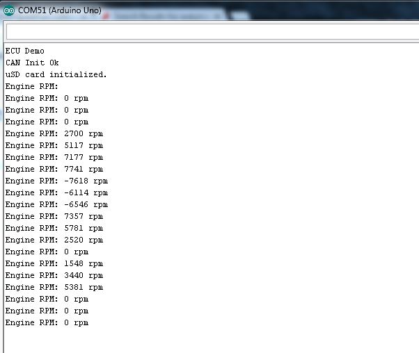
If you've uncommented the lines for serial debugging, you should see something like this:
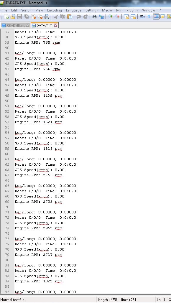
Once you have collected some readings, you can pull your uSD card out and take a look at the data recorded. There should be a file on your uSD card called "DATA.TXT", and it should include information like the following:
Once you've verified data is being stored to the uSD card, you're good to go! You've successfully interfaced with your vehicle's CAN-Bus and can now start digging into diagnostic codes and building projects around your engine's data.
Resources and Going Further
Once you've gotten the basic functionality of the CAN-Bus shield working, you can start hacking your car and interfacing your own electronics to your vehicle. Try checking out different PIDs on the CAN-Bus with your vehicle, or see if you can interface the CAN-Bus to control LEDs, speakers, and more!
For more information, check out the resources below:
- Schematic (PDF)
- Eagle Files (ZIP)
- Datasheets
- GitHub Repository
- SFE Product Showcase: Yes We CAN!
- GitHub Repo: CarHUD - Demo code used in the product showcase.
- SparkFun According to Pete #56: How CAN BUS Works
- SparkFun According to Pete #57: How OBD2 Works
Or check out these videos from According to Pete's explanation of CAN BUS and OBD-II:
Need some inspiration for your next project? Check out some of these related tutorials:
OBD II UART Hookup Guide
Getting Started with OBD-II
AST-CAN485 Hookup Guide
If you have any feedback, please visit the comments or contact our technical support team at TechSupport@sparkfun.com.