Logic Levels
 bri_huang
 Introduction
We live in a world of analog signals. In digital electronics, however, there are only two states -- ON or OFF. Using these two states, devices can encode, transport, and control a great deal of data. Logic levels, in the broadest sense, describes any specific, discrete state that a signal can have. In digital electronics, we generally restrict our study to two logic states - Binary 1 and Binary 0.
Covered in This Tutorial
- What is a logic level?
- What are common standards for logic levels in digital electronics.
- How to interface between different technologies.
- Level shifting
- Voltage Buck-Boost Regulators
Suggested Reading
This tutorial builds on basic electronics knowledge. If you haven't already, consider reading these tutorials:
What is a Circuit?
Voltage, Current, Resistance, and Ohm's Law
Binary
What is a Logic Level?
Put simply, a logic level is a specific voltage or a state in which a signal can exist. We often refer to the two states in a digital circuit to be ON or OFF. Represented in binary, an ON translates to a binary 1, and an OFF translates to a binary 0. In Arduino, we call these signals HIGH or LOW, respectively. There are several different technologies that have evolved over the past 30 years in electronics to define the various voltage levels.
Logic 0 or Logic 1
Digital electronics rely on binary logic to store, process, and transmit data or information. Binary Logic refers to one of two states -- ON or OFF. This is commonly translated as a binary 1 or binary 0. A binary 1 is also referred to as a HIGH signal and a binary 0 is referred to as a LOW signal.
The strength of a signal is typically described by its voltage level. How is a logic 0 (LOW) or a logic 1 (HIGH) defined? Manufacturers of chips generally define these in their spec sheets. The most common standard is TTL or Transistor-Transistor Logic.
Active-Low and Active-High
When working with ICs and microcontrollers, you'll likely encounter pins that are active-low and pins that are active-high. Simply put, this just describes how the pin is activated. If it's an active-low pin, you must "pull" that pin LOW by connecting it to ground. For an active high pin, you connect it to your HIGH voltage (usually 3.3V/5V).
For example, let's say you have a shift register that has a chip enable pin, CE. If you see the CE pin anywhere in the datasheet with a line over it like this, CE, then that pin is active-low. The CE pin would need to be pulled to GND in order for the chip to become enabled. If, however, the CE pin doesn't have a line over it, then it is active high, and it needs to be pulled HIGH in order to enable the pin.
Many ICs will have both active-low and active-high pins intermingled. Just be sure to double check for pin names that have a line over them. The line is used to represent NOT (also known as bar). When something is NOTTED, it changes to the opposite state. So if an active-high input is NOTTED, then it is now active-low. Simple as that!
TTL Logic Levels
A majority of systems we use rely on either 3.3V or 5 V TTL Levels. TTL is an acronym for Transistor-Transistor Logic. It relies on circuits built from bipolar transistors to achieve switching and maintain logic states. Transistors are basically fancy-speak for electrically controlled switches. For any logic family, there are a number of threshold voltage levels to know. Below is an example for standard 5V TTL levels:
VOH -- Minimum OUTPUT Voltage level a TTL device will provide for a HIGH signal.
VIH -- Minimum INPUT Voltage level to be considered a HIGH.
VOL -- Maximum OUTPUT Voltage level a device will provide for a LOW signal.
VIL -- Maximum INPUT Voltage level to still be considered a LOW.
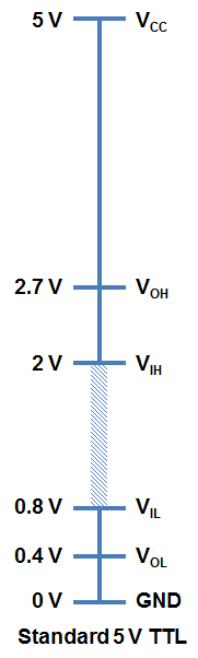
You will notice that the minimum output HIGH voltage (VOH) is 2.7 V. Basically, this means that output voltage of the device driving HIGH will always be at least 2.7 V. The minimum input HIGH voltage (VIH) is 2 V, or basically any voltage that is at least 2 V will be read in as a logic 1 (HIGH) to a TTL device.
You will also notice that there is cushion of 0.7 V between the output of one device and the input of another. This is sometimes referred to as noise margin.
Likewise, the maximum output LOW voltage (VOL) is 0.4 V. This means that a device trying to send out a logic 0 will always be below 0.4 V. The maximum input LOW voltage (VIL) is 0.8 V. So, any input signal that is below 0.8 V will still be considered a logic 0 (LOW) when read into the device.
What happens if you have a voltage that is in between 0.8 V and 2 V? Well, your guess is as good as mine. Honestly, this range of voltages is undefined and results in an invalid state, often referred to as floating. If an output pin on your device is “floating” in this range, there is no certainty with what the signal will result in. It may bounce arbitrarily between HIGH and LOW.
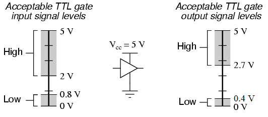
Here is another way of looking at the input / output tolerances for a generic TTL device.
3.3 V CMOS Logic Levels
As technology has advanced, we have created devices that require lower power consumption and run off a lower base voltage (Vcc = 3.3 V instead of 5 V). The fabrication technique is also a bit different for 3.3 V devices that allows a smaller footprint and lower overall system costs.
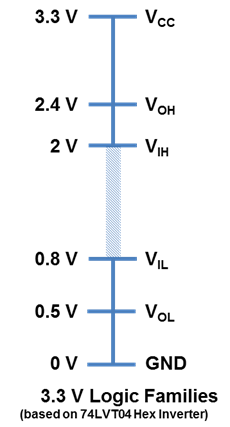
In order to ensure general compatibility, you will notice that most of the voltage levels are almost all the same as 5 V devices. A 3.3 V device can interface with a 5V device without any additional components. For example, a logic 1 (HIGH) from a 3.3 V device will be at least 2.4 V. This will still be interpreted as a logic 1 (HIGH) to a 5V system because it is above the VIH of 2 V.
A word of caution, however, is when going the other direction and interfacing from a 5 V to a 3.3 V device to ensure that the 3.3 V device is 5 V tolerant. The specification you are interested in is the maximum input voltage. On certain 3.3 V devices, any voltages above 3.6 V will cause permanent damage to the chip. You can use a simple voltage divider (like a 1KΩ and a 2KΩ) to knock down 5 V signals to 3.3 V levels or use one of our logic level shifters.

Arduino Logic Levels
Looking at the datasheet for the ATMega328 (the primary microcontroller behind the Arduino Uno and the Sparkfun RedBoard), you might notice that the voltage levels are slightly different.
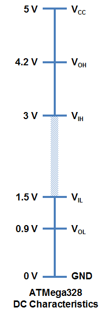
The Arduino is built on a slightly more robust platform. The most noticable difference is that the invalid region of voltages is only between 1.5 V and 3.0 V. The noise margin is greater on the Arduino and it has a higher threshold for a LOW signal. This makes building interfaces and working with other hardware much simpler.
Interested in learning more foundational topics?
See our Engineering Essentials page for a full list of cornerstone topics surrounding electrical engineering.

Resources and Going Further
Now that you've got the gist of one of the most common concepts in electronics, there's a world of new stuff to learn!
Would you like to learn how a microcontroller, like an Arduino, could read the analog voltage produced by a voltage divider? You can do so with our analog-to-digital converters tutorial.
Analog to Digital Conversion
Learn how to use varrying levels of voltage to control other devices with our pulse width modulation tutorial.
Pulse Width Modulation
You may also be interested in using voltage divider circuits and logic level converters to switch from one logic level to the next.
Serial Communication
Voltage Dividers
TXB0104 Level Shifter Hookup Guide
Bi-Directional Logic Level Converter Hookup Guide
Qwiic Shield for Arduino & Photon Hookup Guide
Single Supply Logic Level Converter Hookup Guide
PCA9306 Logic Level Translator Hookup Guide (v2)
Or add a transistor or relay to control devices operating at higher voltages like the tutorials listed below!
LED Light Bar Hookup
Transistors
Beefcake Relay Control Hookup Guide
Internet of Things Experiment Guide
References
- Voltage: 3.3 vs 5
- Migration From 3.3 V to 2.5 V Power Supplies for Logic Devices
- Logic Threshold Voltage Levels
- Transistor–transistor logic
- 3V Tips 'n Tricks
- 5 V TTL and CMOS Input and Output Voltage Levels
- For a more "in-depth" look at why 3.3 V was chosen as the next lowest voltage level, check out this forum discussion.