Beefcake Relay Control Hookup Guide
 MTaylor
 Introduction
The Beefcake Relay Control Kit is a way to switch loads that could not normally be driven with a microcontroller, such as AC lights, motors, batteries, solenoids, pumps, and more!

This hookup guide talks about safety, takes you through the assembly process of the Beefcake Relay Control kit and shows how to test it using the most basic Arduino sketch.
Suggested Reading
- Through-Hole Soldering -- If you're unfamiliar with soldering, start here.
- Redboard Hookup Guide -- New to microcontrollers? Pick up a redboard and start here.
- The Relay Tutorial -- Controlling Big, Mean, Devices.
- Beefcake Relay Control Kit GitHub Repo -- contains source material.
Safety and Insulation
This product will potentially be used for mains wiring, so please read this section discussing how much space is required to prevent arcing.
There are a lot of standards out there, like the IEC standards, the UL standards, and the IEEE standards. These cover anything from test techniques, communication interfaces and of course safety. Each country requires a different set of standards for commercially released products, which is an experienced full time position just to make sense of.
The Beefcake Relay Control is a prototyping or component type thing and abides by no standards, but it was designed with safety in mind. Because it's not a full product though, there is no guarantee that it will be used safely by you, the customer, so please be careful.
Making standards is good for business and compatibility but is also a business itself, so the standards can't be found for free. However, creative Google searches can reveal the pertinent tables which have obviously come from the standards. Information from the standards have been boiled down to creepage and clearance calculatators for PCBs such as www.creepage.com. These can be used to come up with safe distances.
Play around with the creepage.com calculator, and see how the distances change. This section is intended to inform and not to scare. The terminology is a little odd so here's a few terms that my demystify the calculator settings.
Functional insulation
Functional insulation is intended to meet the lowest level of isolation for a given voltage. 250VAC is about 1mm.
Basic insulation
This provides a level above nominal to allow surges and other common line disturbances to not cause a breakdown. For 250VAC, 2mm is required.
Double insulation
To make things safe for people to come in contact with, most standards require a second layer so that one can be damaged, and the isolation characteristic is maintained. Of course, this would be twice basic, or 4mm for 250VAC.
Reinforced insulation
Reinforced insulation has the same insulative properties as double, but it is rated to be robust enough to not get cracks and pinholes such that it can be used in place of proper grounding.
Creepage and Clearance
Creepage is defined as the shortest distance between conductive surfaces along the surface of the PCB. It's easier to conduct along the surface of an object than in free space, so this measure is the distance electrons would have to crawl to get from one conductive thing to another, along the surfaces in between. This will be farther than the clearance requirements.
Clearance is defined as the shortest distance between conductive things (like pads). Or, if there were an arc between the two things, what would the most likely path be?
What this means for the Beefcake Relay Control
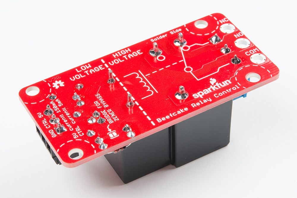
Take a look at the PCB with strong lighting through it. The raw fiberglass of the board lets the light through but the copper doesn't. It's easy to see the traces and spacing this way.
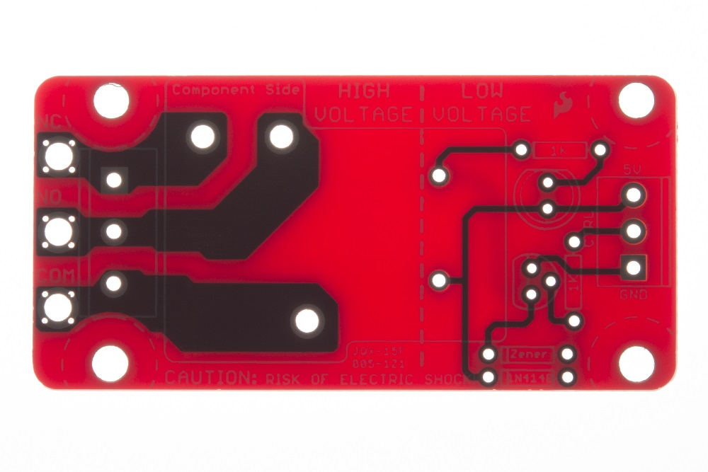
There is a lot of distance between the high voltage and low voltage sides. There's enough that you should be able to safely touch anything on the low voltage side, but please don't. It's good practice to avoid working with any circuit that is connected to mains.
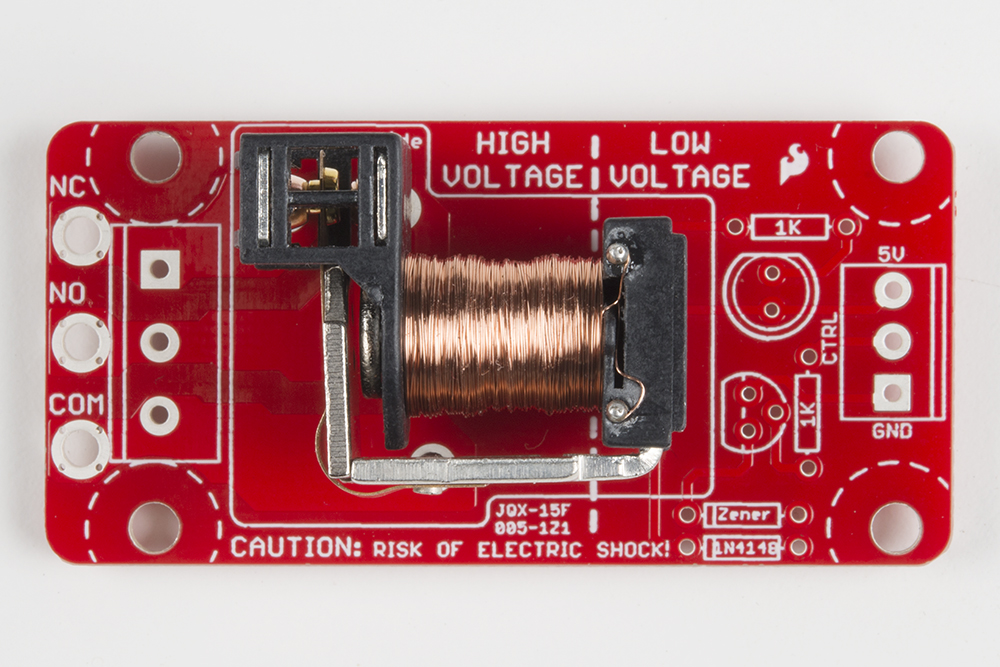
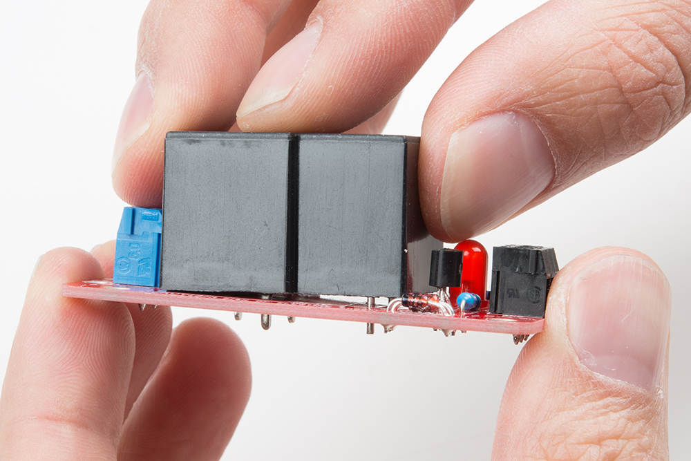
Peeking inside the relay we can see a good distance between the low voltage windings and the high voltage contacts. This relay is rated to 2500VAC isolation between the coil and contacts, but manufacturing has statistical failure rates, and the user should always be wary of the dangers.
Assembly
The Beefcake Relay Control kit is relatively straight forward to assemble. This section outlines what tools will be needed and shows the assembly process.
Materials
The kit contains the following parts:
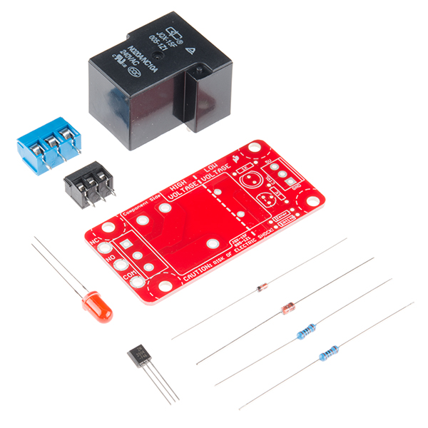
- An electromechanical Relay
- 2x Terminal blocks, light gauge for signal and heavy for output
- Coil-active LED
- Bipolar junction transistor (BJT)
- 2x Current limiting resistors
- Flyback arrestor diode
- Zener diode for discharge
Tools
The following tools are recommended.
- A soldering iron with 50 watts of power capability.
- Some solder, either leaded or lead-free.
- A magnifying glass or loupe.
- A vise to hold the PCB as you work.
Building The Beefcake Relay Control
The Beefcake uses standard through-hole techniques. Components will be passed through the holes, soldered, and the leads trimmed. It's best to start with the shortest components working up to the taller ones. This is so they stay pressed in place while the board is upside down against a work surface.
Start with the resistors. Bend the leads so they form 90 degree angles as close to the resistor body as possible.
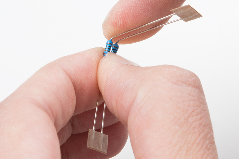
Feed them into the place marked 1k. They will sit over the silkscreen box.
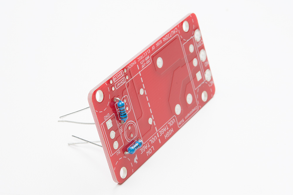
Next, bend the diode leads. The diode bodies are shorter, so it's not necessary to get the bends right close. They should be the same widths as the resistors after bending.
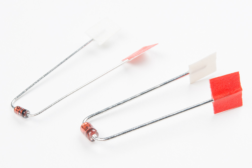
Insert the diodes. The fat diode is the 9.1V zener, and should be marked 4739. Place it over the silkscreen box labled "Zener" with the black band towards the white silkscreen stripe. The smaller diode should be labled 4148 and is a standard high-speed diode. Place it over the box labled N4148 with the black stripe towards the silk stripe.

Now, flip the board, and solder those components forming nice shiny cones around the leads. A weight, like the solder stand, can be used to hold the board, or it can be placed in a vice.
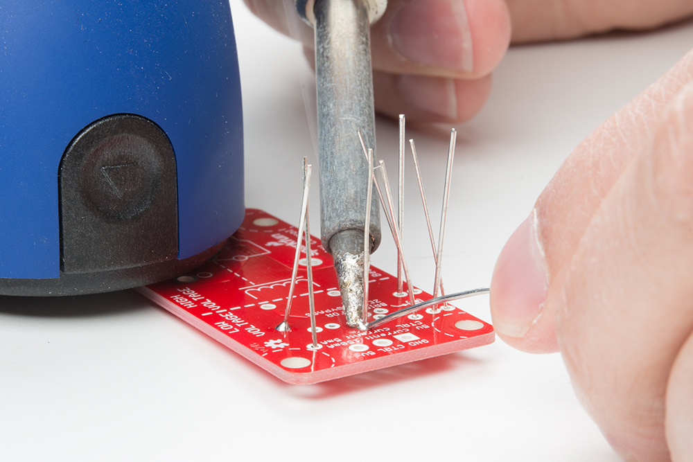
Clip the component leads right at the top of the solder cones.

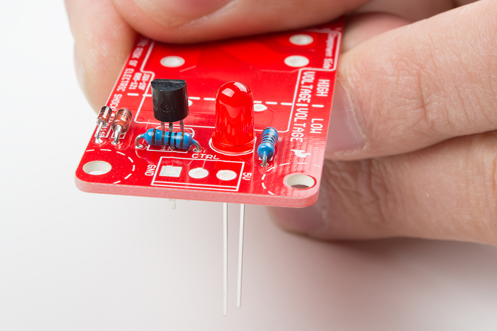
Next, prepare the BJT. Leave the outer two legs straight. Bend the inner leg in an 'S' curve so that it is spaced evenly from the other two legs in an equilateral triangle.

Fit the BJT and LED into the board, minding that the flat side of the LED matches the flat part of the silkscreen circle.
Solder them in place, and trim the leads.
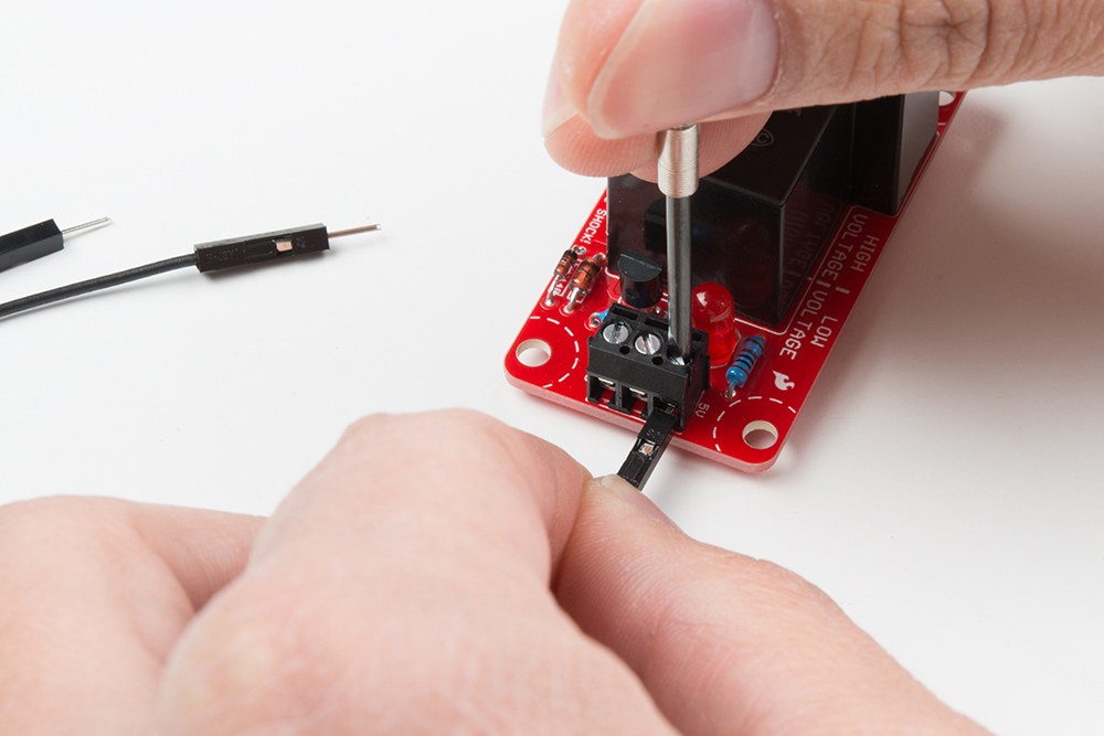
Attach the screw terminals. Orient them so the apertures face outward. These will stay in pretty well, so flip it and solder in place.
The last component is the relay. The relay has thick leads for current capacity, so they may need a little work getting inserted. Once they are all positioned, it should sit flush with the PCB.
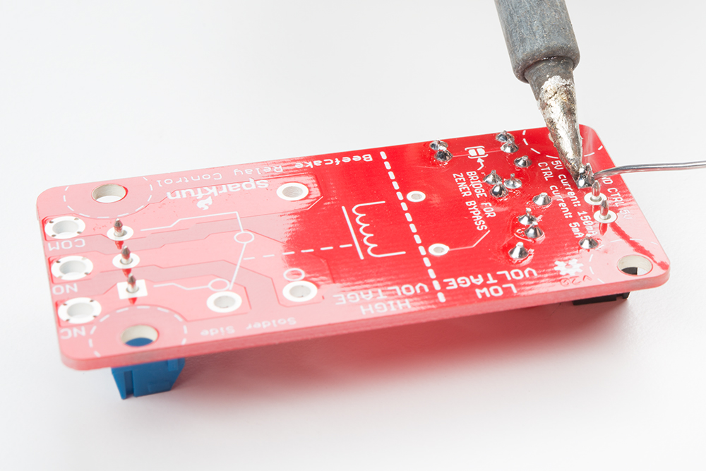
The extra copper involved in carrying the current means it can take extra heat to get the solder to flow, but it is very important. A cold solder joint will cause extra resistance. With the recommended Hakko iron set to 700 degrees, there should be no problem, but the iron will have to be held on longer than normal. Feed extra solder if the joint is looking dirty, the flux will come out, and you can scoop away the extra solder with the iron right after.

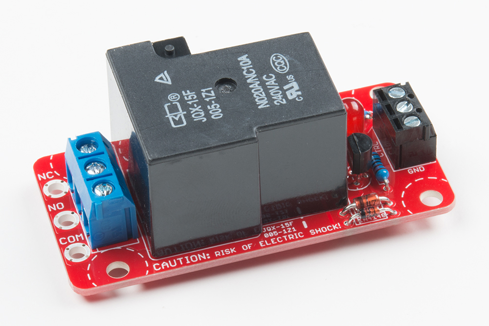
Congratulations! You now have a completed Beefcake Relay Control circuit. Here's what the final product will look like.
Example: Arduino Control
Now, it's time to make the relay sing the song of its people. Connect the 5V terminal to 5V power capable of supplying 150mA, the ground to ground, and a signal wire from a digital output to the control pin (CTRL).
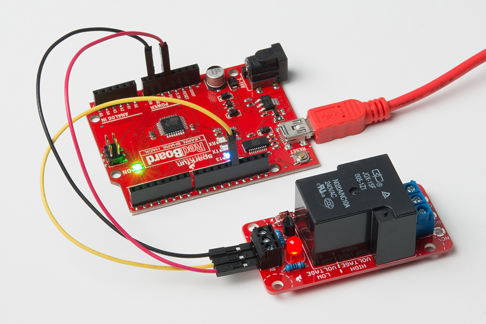
A basic example is the blink.ino sketch. Connect the signal pin to digital out 13, which is the same as the LED. Connect Ground to the GND terminal and 5 volts to the 5V terminal as shown below.

Now, as the LED on the microcontroller board blinks, the relay will energize, and the Beefcake's LED will illuminate. You should hear a pleasant clicking sound every second.
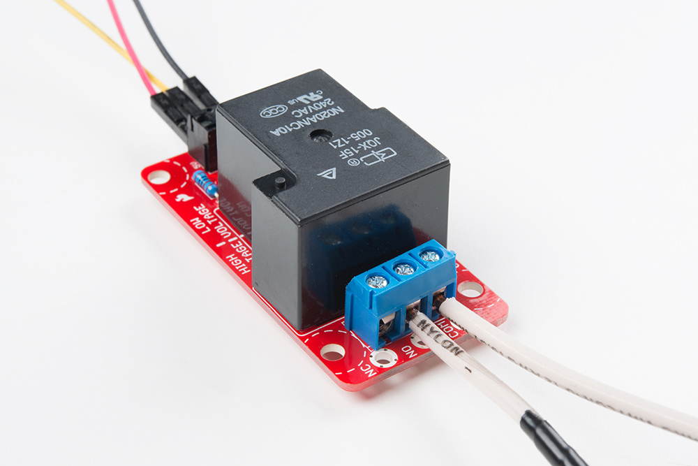
Ahh, so satisfying. But, really this should be used to switch a load. Here I've attached 12 gauge solid house wiring into the terminals, which was a pretty tight fit. The terminals are only specified to 14 gauge wire.
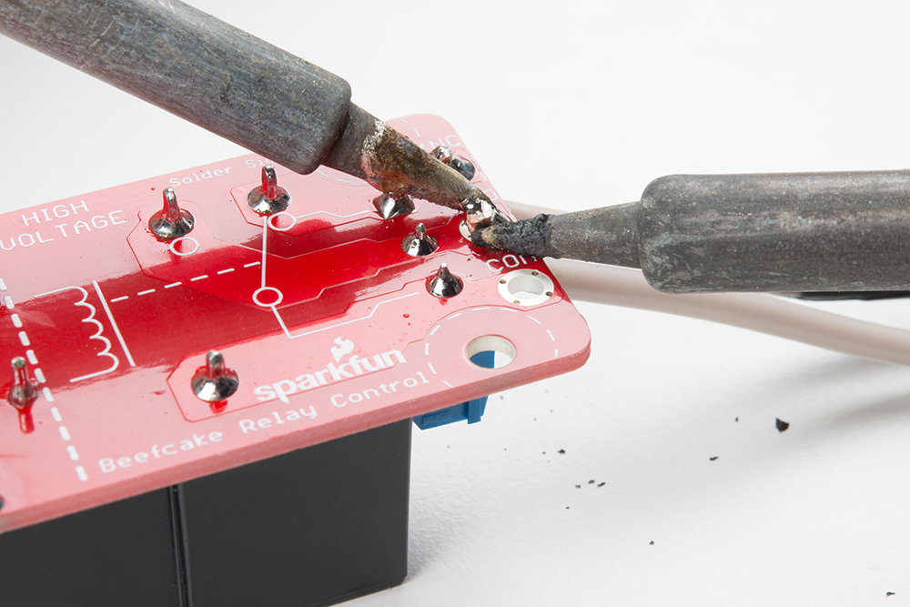
If you would like a more permanent installation, go ahead and solder to the large lugs on the edge of the board. This will take even more heat with the large solid copper wires, so be patient.
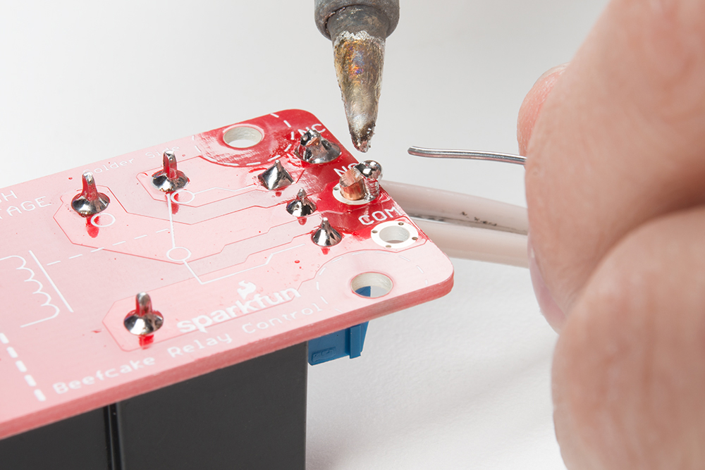
A technique for getting a bit of extra heat in there is to warm up a second iron, blob up a bunch of solder first, the heat with both irons.
Resources and Going Further
You should now have a relay capable of switching loads from a microcontroller. But what to switch? Motors? Floor lamps? Other relays? It's up to you! For more information about the Beefcake Relay Control board, check below!
- Schematic
- Eagle Files
- Datasheet (JQX-15F/005-1Z1)
- Relay Tutorial
- GitHub
Here's a few tutorials to inspire you. They use the Beefcake to switch some fun stuff, including fire.