Blynk Board Bridge Widget Demo
 .Brent.
Introduction
The Bridge Widget available in the Blynk app allows for Device-to-Device communication. No app is required to be running. This demo shows a few ways the Bridge widget can be used for app to app communications, app to board communications, and board to board communications.
For full functionality, two mobile devices and two SparkFun Blynk Boards are required. If you aren't interested in app to app communications, only one mobile device will be required. Mobile devices can be running Android or iOS.
Suggested Reading
This tutorial builds on concepts covered in previous Blynk tutorials. If you have not done so already, we recommend reading these before embarking upon this tutorial:
Hardware Hookup
There is no need to futz with extra hardware to prove concepts. Software developers might appreciate this. Once you have the built in button controlling the built in LED, it's just matter of changing one or two values and clipping on extra hardware.
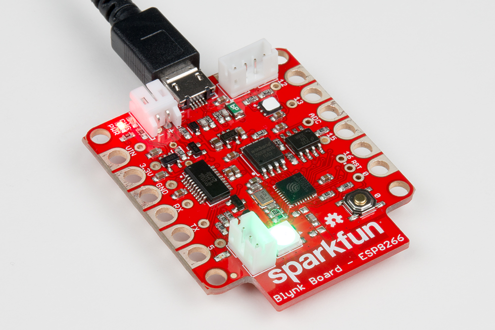
For this tutorial, all you need to do is provide power the the Blynk Boards. This is easiest two ways: USB, or a 3.7V LiPo battery (1S).
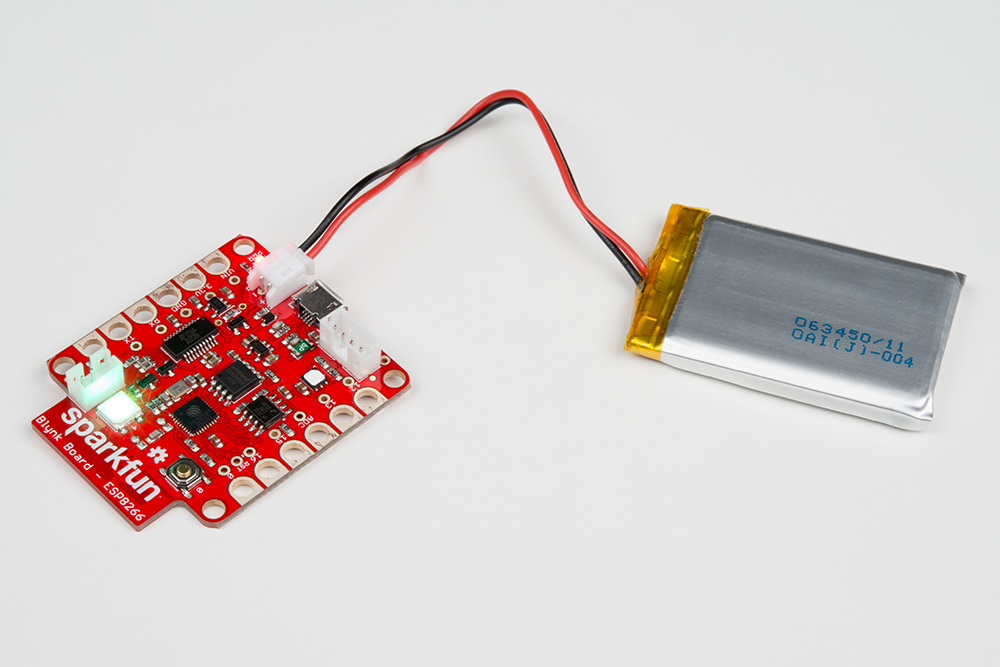
Powering the device with a USB cable connected to your development machine is the easiest way to prototype. Load new code, and it just runs.
Mobile Apps
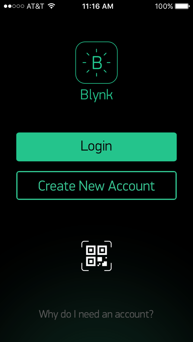
To create a mobile app, first make sure you have the Blynk app installed. If you don't, please install the version for your OS from one of these two sources:


Exact instructions are beyond the scope of this tutorial. Visit the Getting Started with Blynk Guide, if you have not done so already. Once you have the app installed, login, or create a new account.
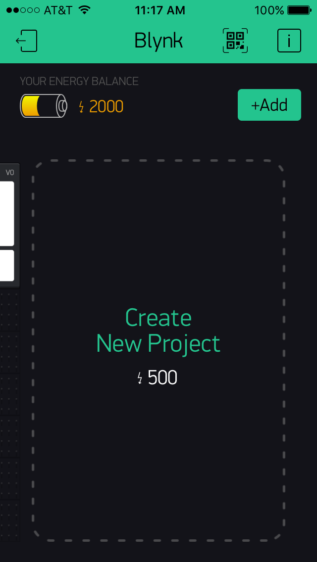
Once you have logged in, select the large Create New Project button.
This will bring you to where you name the project. Select the hardware that you will be connecting to, and get your authentication token. This token (7DF0F1DE119F48149EFF64BC7B2FBD11 in this example) will be very important later. I find that emailing it to myself is easier than typing it out. It will be sent to the email account that you registered with when you created your account.
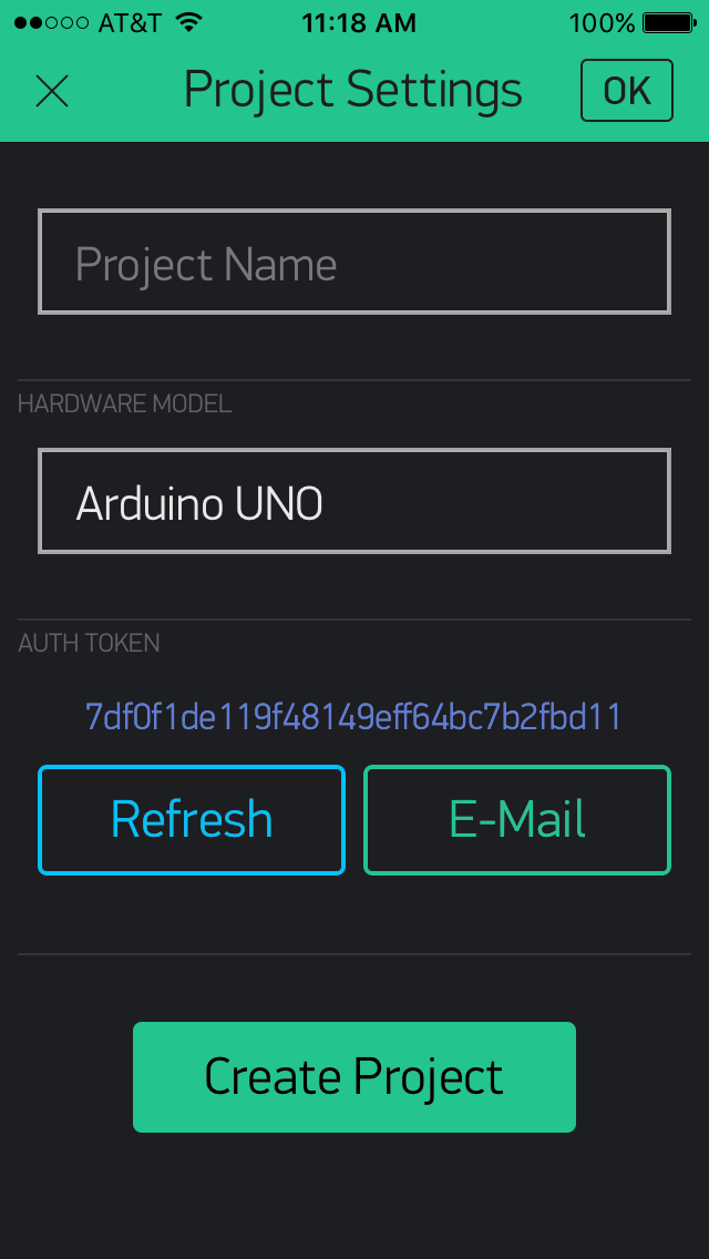
I gave my project a name that matches the sketch designed to work with it. This is unnecessary, but helps keep confusion to a minimum. Once you select some SparkFun hardware, note that the theme changes.
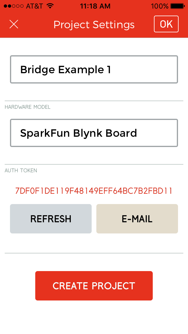
Select the CREATE PROJECT option to create and open the project.
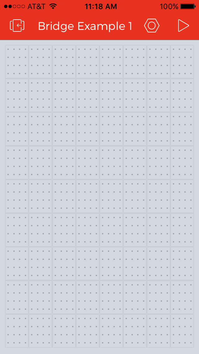
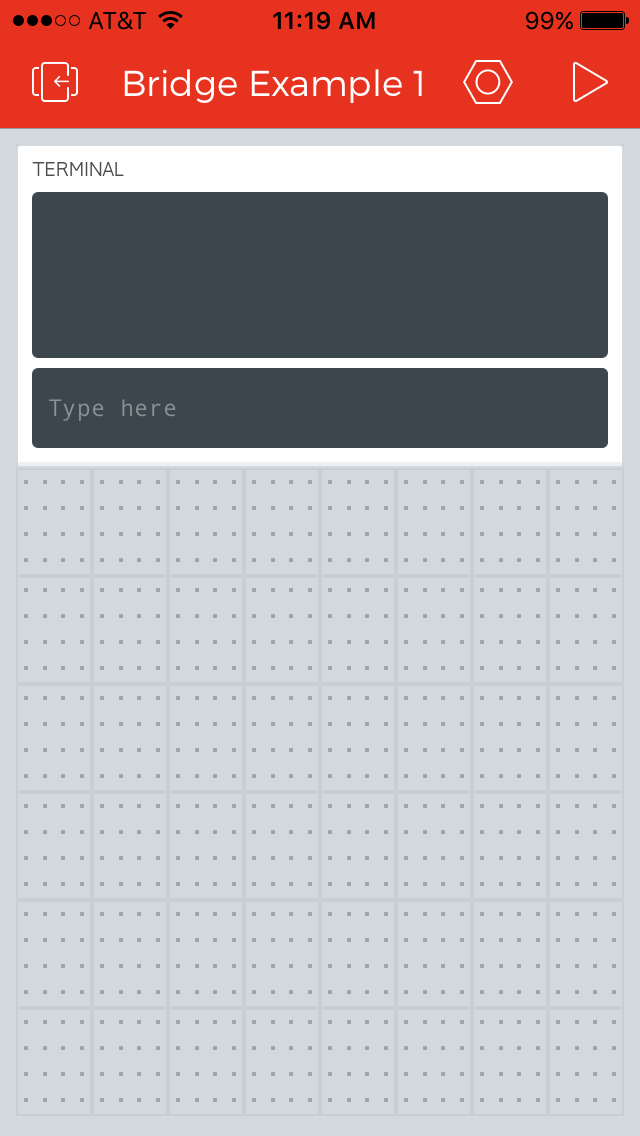
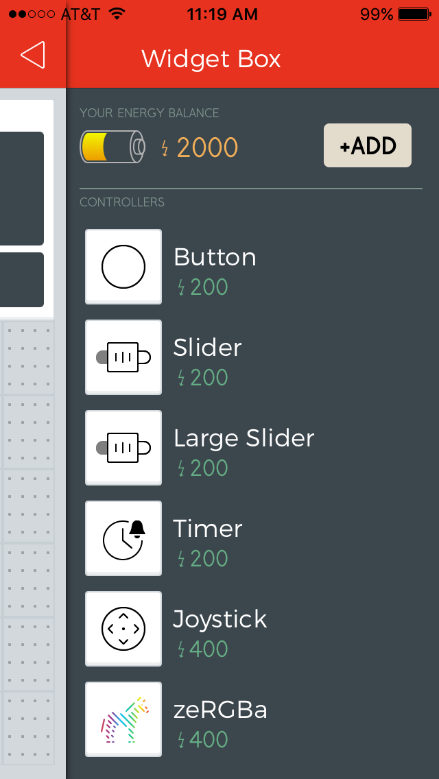
Now that you have an empty project canvas to work with, it's time to start adding UI elements. Let's start with the Terminal widget. You find this by double tapping the canvas and scrolling the sidebar until you see the widget of interest.
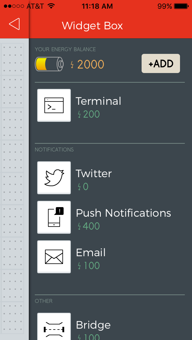
Select the widget, and the Widget Box will close. The selected widget will appear in the next available slot on the canvas.
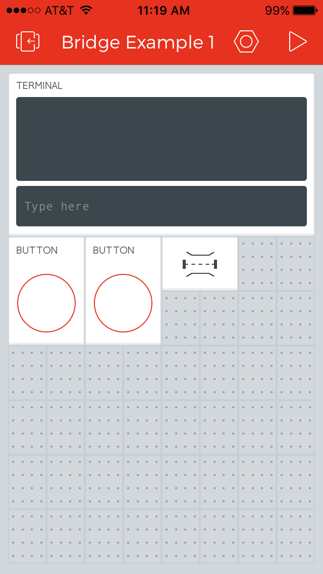
Now that you have a terminal widget in place, find the button widget in the Widget Box.
Follow the same procedure to place the Bridge widget. It can be found in the other section of the Widget Box at the bottom.
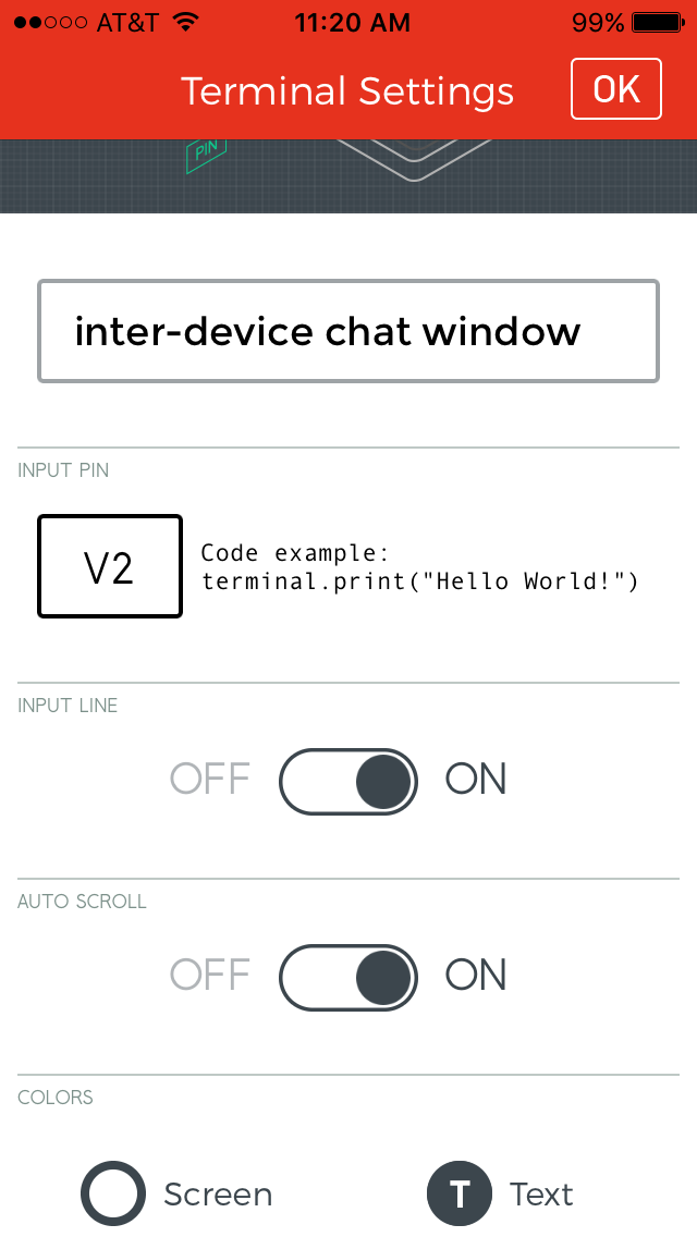
Once all of the widgets are placed, it's time to configure them. Start by configuring the Terminal widget. Give it a name/label. It doesn't matter what case you enter, it will be converted to upper CASE.
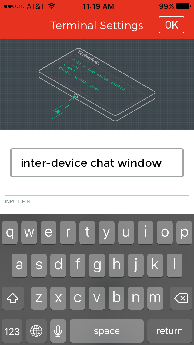
In order to interact with a widget, you need to assign a pin to it. Some widgets use real, physical pins, while others use virtual pins. All of the UI in this example uses virtual pins. In this case, I've chosen to connect the terminal to virtual pin 0. I left the other settings for the Terminal widget at their default values.
The procedure is the same for the Button widgets as it is for the Termial widget. Give them names/labels, and select a pin to communicate through. I think case I'm using virtual pin zero to control the local LED connected to GP5. The reason for using a virtual pin rather than a physical pin will be explained in the firmware section.
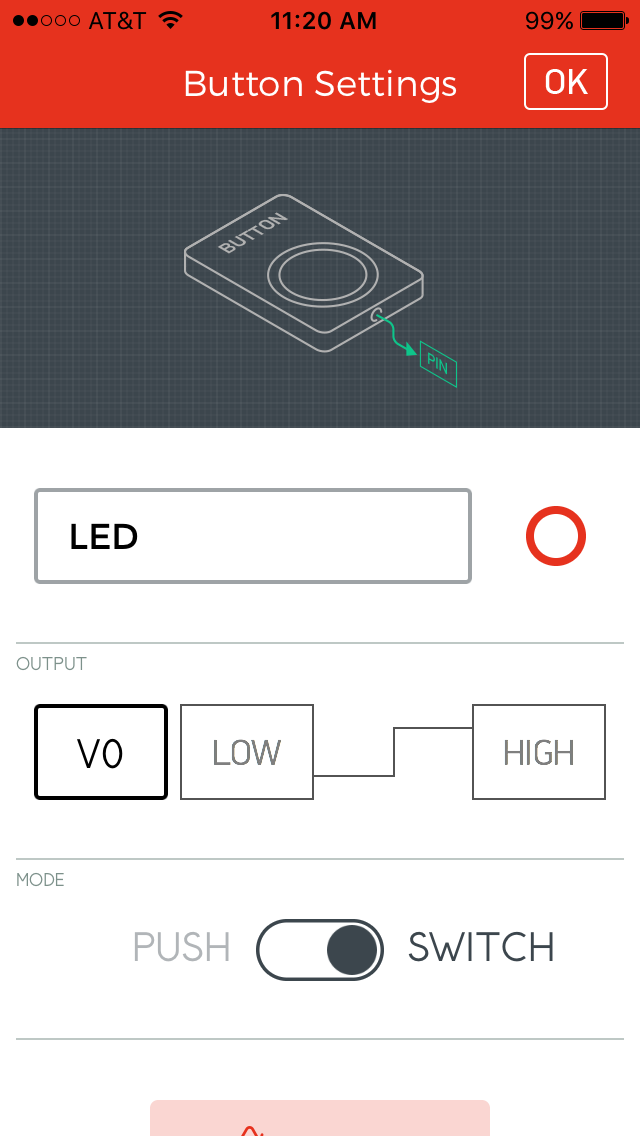
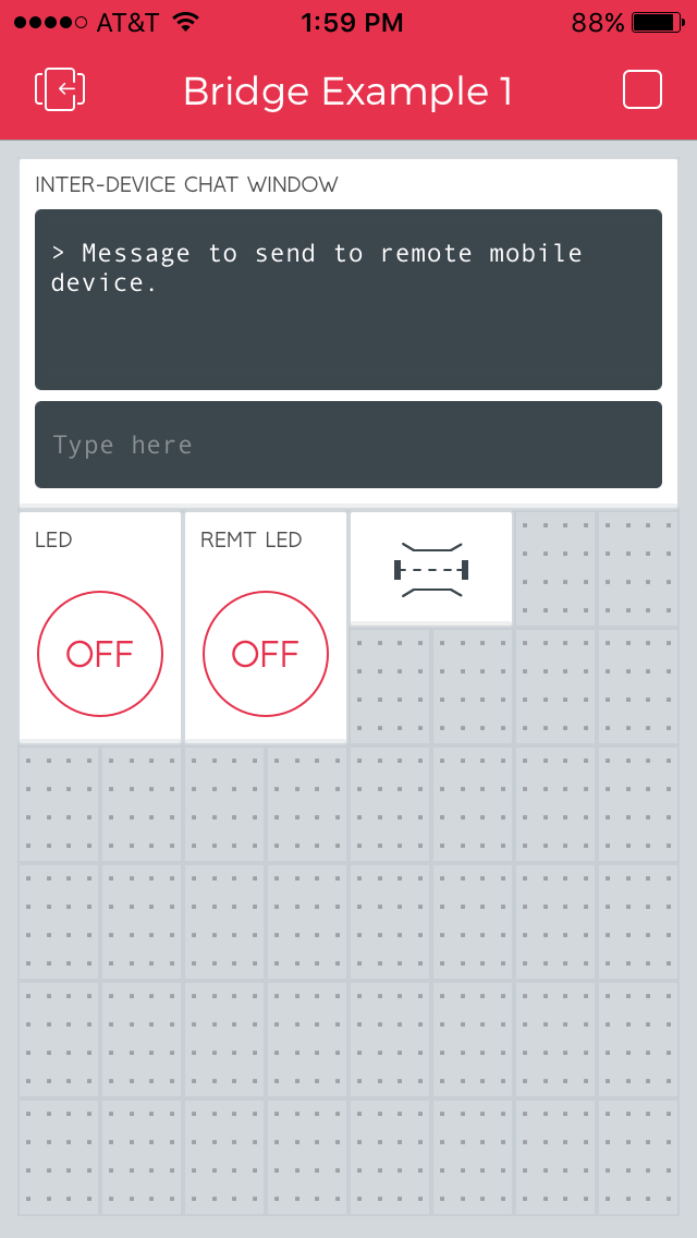
Note that in the image above, I've also changed the button from PUSH (momentary) to SWITCH (latching). The other configuration options for Button widgets control to color. That wasn't important to this demo, and I left the defaults. Here is what the finished app should look like:
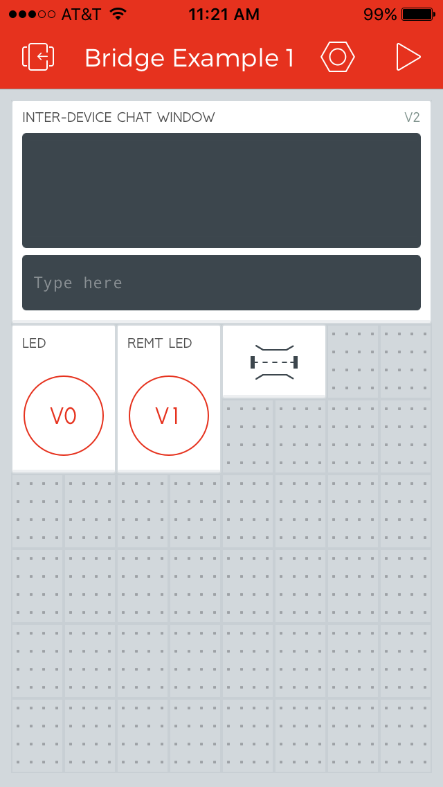
When the triangle in the upper-right corner is pressed, the app will run, and the details of the wiring are hidden from the user.
Firmware
The firmware for this demo is Arduino code. For detailed information on getting the Blynk libraries installed and your development environment configured, please visit the Blynk Board Arduino Development Guide.
Configuration
One major way that the firmware for this demo differs from "standard" Blynk firmware is that you need a second authentication code.
language:c
char auth[] = "7DF0F1DE119F48149EFF64BC7B2FBD11"; // Put your Auth Token here
char remoteAuth[] = "RemoteAuthToken"; // Auth token of bridged device
To get this second authentication code, you need a second project on your mobile device. For the chat to also work, you will want to start the second project on a second mobile device logged into the same account. Once you have the second project for a secondary Blynk Board, that token can be entered as the remoteAuth for the primary Blynk Board. These two lines are the only differences between Bridge_Example_1.ino and Bridge_Example_2.ino. Two were created as a convenient way keep the confusion low and to make tweaks to one but not both easier.
The next section to configure is the section of aliases used to tell the body of the code which virtual pin was chosen in the app. These don't need to be changed if you followed along in the previous section on the mobile app configuration. In both the code and in the mobile app, we have the local LED button mapped to virtual pin 1 (V1). We have configured the second button labeled REMT LED in the app to use virtual pin 2 (V2). Here in the code we defined an alias REMOTE_LED_BUTTON for V2. This section allows us to use the exact same code for many bridged devices.
language:c
// Virtual Pins:
#define TERMINAL                 0  // V0
#define LOCAL_LED_BUTTON         1  // V1
#define REMOTE_LED_BUTTON        2  // V2
#define TERMINAL_RECEIVE         3  // V3
#define BRIDGE                   4  // V4
#define LOCAL_LED_RECIEVE        5  // V5
#define REMOTE_LED_STATUS_UPDATE 6  // V6
The final configuration needed is to tell the Blynk Board how to connect to the Wi-Fi®. Replace SSID with the SSID (the name of your Wi-Fi® network) leaving the double quotes. Also replace PASSWORD with the actual password for your network, again leaving the double quotes.
language:c
Blynk.begin(auth, "SSID", "PASSWORD");  // Here your Arduino connects to the Blynk Cloud.
How It Works
Physical Button
Let's start with the physical button on the Blynk Board. This button will be used to toggle the LED on the other Blynk Board.
This button connects GPIO0 to ground when pressed. This is called active low; the signal goes low, when the button is pressed/active. An internal pull-up resistor is used to keep this signal high when inactive. An interrupt service routine is used to immediately capture the button press event, but the resulting action isn't taken until the main loop of the code gets around to doing it. This keeps more important things running fast. Here is the code snippet to configure what was just described.
language:c
// Setup the onboard button
pinMode(BUTTON_PIN, INPUT_PULLUP);
// Attach BUTTON_PIN interrupt to our handler
attachInterrupt(digitalPinToInterrupt(BUTTON_PIN), onButtonPress, FALLING);
The second parameter to the attachInterrupt function call is the name of the interrupt service handler, onButtonPress.
language:c
// Interrupt service routine to capture button press event
ICACHE_RAM_ATTR void onButtonPress()
{
  // Invert state, since button is "Active LOW"
  wasButtonPressed = !digitalRead(BUTTON_PIN);
}
This function is called when the physical button is pressed. Since the processor may be in the middle of doing something with more critical timing, this function does as little as possible, and the event is dealt with later. Here we have a variable wasButtonPressed that keeps track of whether or not the button was pressed. We store the opposite of the current state of the pin in this variable. The opposite is obtained with the ! operator. We read this pin a second time as a form of debouncing. A real button press should send the value of that pin low, and it should remain low at least the fraction of a second it takes to jump to this function and double check the state. This avoids changing state based on fast transient glitches.
Next, let's discuss the main loop:
language:c
void loop()
{
  Blynk.run(); // All the Blynk Magic happens here...

  if (wasButtonPressed) {
    // This can be seen in the Serial Monitor
    BLYNK_LOG("Physical button was pressed.");
    // Toggle state
    remoteLedState ^= HIGH;
    // Send new state to remote board LED
    bridge.virtualWrite(LOCAL_LED_RECIEVE, remoteLedState);
    // Update state of button on local mobile app
    Blynk.virtualWrite(REMOTE_LED_BUTTON, remoteLedState);
    // Clear state variable set in ISR
    wasButtonPressed = false;
  }
}
Two things happen here. First, we let the Blynk library do its thing. Next, we check to see if the physical button was pressed. If the button had been pressed since the last time this check was run, we have a few things to do.
First, if the Blynk Board is connected via a micro USB cable to a computer running a terminal emulator or the Arduino Serial Monitor, we write a debug message to that at 9600 baud. This is done with BLYNK_LOG("Physical button was pressed.");. This code can be compiled out if the first line of actual code in the sketch is removed or commented out (#define BLYNK_PRINT Serial).
A state variable keeping track of the state of the remote LED is toggled. This is done with remoteLedState ^= HIGH; but could also be done with something like remoteLedState = 1 - remoteLedState;, or remoteLedState = !remoteLedState;.
Next, we send the new state across the bridge doing a virtual write to the remote LOCAL_LED_RECIEVE virtual pin. On the other end is a function that handles the value sent.
After we have told the remote devices to update, we need to update the state on the mobile app attached to this Blynk Board. We do this with a virtual write to the REMOTE_LED_BUTTON with the new state value.
The final thing to do is clear the variable that indicates we have an unhandled button press, wasButtonPressed. This causes the code block we are in to be skipped until the button is pressed again.
To follow along to logical flow of a physical button press, let's cover the function that handles when another device signals that its button has been pressed:
language:c
// Remote device triggered an LED change. Update the LED and app status.
BLYNK_WRITE(LOCAL_LED_RECIEVE)
{
  // This can be seen in the Serial Monitor
  BLYNK_LOG("Remote device triggered LED change");

  ledState = param.asInt();
  // Turn on LED
  digitalWrite(LED_PIN, ledState);
  // Set state of virtual button to match remote LED
  Blynk.virtualWrite(LOCAL_LED_BUTTON, ledState);
}
The new or important items found in this function are the digitalWrite and the virtualWrite. After updating the state of the LED, this value is sent to the GPIO connected to the LED. We then update the UI on the mobile app associated with this board.
The previous code block handled updating the GUI associated with the board that had the button pressed. This block update the physical LED and the GUI associated with the board with the LED that changed. One virtual button press updated a physical pin and two GUI elements.
LED Button in the Mobile App GUI
When the button labeled LED is pressed, the following function is called. The first bit is nothing new. We update the state variable and log this info via a serial connection, if it exists.
language:c
// Virtual button on connected app was used to change remote LED.
// Tell remote devices about the change.
BLYNK_WRITE(REMOTE_LED_BUTTON)
{
  remoteLedState = param.asInt(); // Update state with info from remote
  BLYNK_LOG("New remote LED state: %s", param.asInt() ? "HIGH" : "LOW");
  // Send updated status to remote board.
  bridge.virtualWrite(LOCAL_LED_RECIEVE, remoteLedState);
}
The last statement in this function sends the remoteLedStat to the other Bkynk Board's LOCAL_LED_RECEIVE virtual pin over the bridge. The bridge was configured in this line:
language:c
WidgetBridge bridge(BRIDGE);
BRIDGE was defined earlier in the code to be virtual pin 4.
The other end of the bridge reacts to this signal with the following function. Nothing new to see here, we log via the serial port if it exists, update the state variable, update the physical pin, and finally update the state of the GUI.
language:c
// Remote device triggered an LED change. Update the LED and app status.
BLYNK_WRITE(LOCAL_LED_RECIEVE)
{
  // This can be seen in the Serial Monitor
  BLYNK_LOG("Remote device triggered LED change");

  ledState = param.asInt();
  // Turn on LED
  digitalWrite(LED_PIN, ledState);
  // Set state of virtual button to match remote LED
  Blynk.virtualWrite(LOCAL_LED_BUTTON, ledState);
}
Remote LED Button in the Mobile App GUI
The remote LED button in the mobile app GUI behaves roughly the same as the LED button. In this case the button is labeled REMT LED. It uses the following functions. This first is called when the button in the app is pressed.
language:c
// Virtual button on connected app was used to change remote LED.
// Tell remote devices about the change.
BLYNK_WRITE(REMOTE_LED_BUTTON)
{
  remoteLedState = param.asInt(); // Update state with info from remote
  BLYNK_LOG("New remote LED state: %s", param.asInt() ? "HIGH" : "LOW");
  // Send updated status to remote board.
  bridge.virtualWrite(LOCAL_LED_RECIEVE, remoteLedState);
}
That function sends a signal handled on the other end of the bridge handled with the following function.
language:c
// Remote device triggered an LED change. Update the LED and app status.
BLYNK_WRITE(LOCAL_LED_RECIEVE)
{
  // This can be seen in the Serial Monitor
  BLYNK_LOG("Remote device triggered LED change");

  ledState = param.asInt();
  // Turn on LED
  digitalWrite(LED_PIN, ledState);
  // Set state of virtual button to match remote LED
  Blynk.virtualWrite(LOCAL_LED_BUTTON, ledState);
}
Inter-Device Chat Window
Another part of this demo is sending text over the bridge. Alone this isn't the most amazing use of the technology, but in the case of an Internet outage a local Blynk Server and a Wi-Fi router could be setup for a phone to phone chat service.
The first requirement is to setup a Terminal widget to go with the one added in the mobile app.
language:c
// Attach virtual serial terminal to TERMINAL Virtual Pin
WidgetTerminal terminal(TERMINAL);
Next, a function takes the output of this widget and sends it to another Blynk Board.
language:c
// You can send commands from Terminal to your hardware. Just use
// the same Virtual Pin as your Terminal Widget
BLYNK_WRITE(TERMINAL)
{
  // Send from this terminal to remote terminal
  bridge.virtualWrite(TERMINAL_RECEIVE, param.asStr());
}
On the other side of the bridge is the following function that takes the received string and writes it to the local terminal.
language:c
// Receive a string on LOCAL_RECEIVE and write that value to the connected
// phone's terminal
BLYNK_WRITE(TERMINAL_RECEIVE)
{
  terminal.println(param.asStr());  // Write received string to local terminal
  terminal.flush();
}
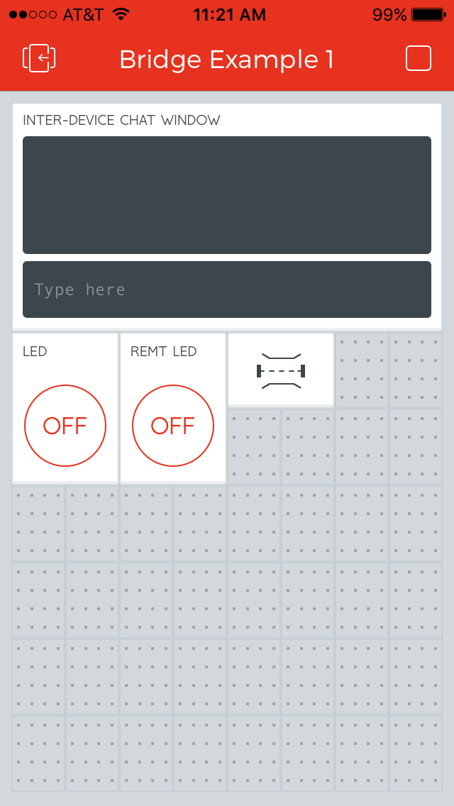
What You Should See
That was quite a lot so let's go over what you will see after uploading code to the respective Blynk boards and running the projects. Try typing into terminal window for either project. This will send a message to the other Blynk board that is connected and vice versa. If you press a "LED" button on the Blynk app associated with the project, you will notice the GUI react to the button press and the blue LED turn on with the Blynk board. If you press the "REMT LED" button on the Blynk app associated with the project or the physical button on the other Blynk board, you will notice the LED turn on with the Blynk board!
Resources and Going Further
In this demo, we used 7 virtual pins. Three of them were used to send various types of data. If your project became more complex and you ran out of virtual pins, you could send all of the data over one by encoding information on one end and decoding it on the other.
This demo was aimed a little more at the software inclined user since it required no extra hardware. It used the built in buttons and LEDs. This could easily be modified to use other pins with whatever you want to connect to them. The button on one end could be replaced with a SparkFun Sound Detector, and the LED on the other Blynk Board could be replaced with SparkFun Beefcake Relay Control Kit. This would allow you to make your own Wi-Fi version of The Clapper. Clap in one room to turn on/off a lamp on another house!
If you need general Blynk Board or Blynk App resources, these may help:
- SparkFun Blynk Board Resources
- Blynk Resources
If you need any technical assistance with your Blynk Board, don't hesitate to contact our technical support team via either e-mail, chat, or phone.