RedBoard Hookup Guide
 jimblom
 Introduction
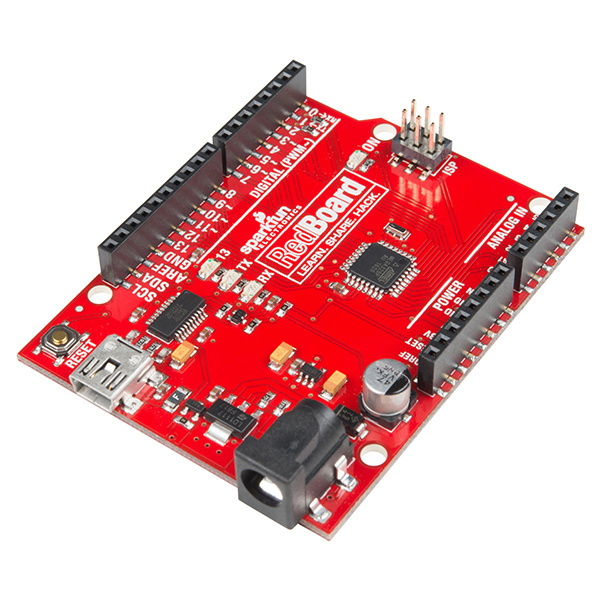
The SparkFun RedBoard is an Arduino-compatible development platform that enables quick-and-easy project prototyping. It can interact with real-world sensors, control motors, display information, and perform near-instantaneous calculations. It enables anyone to create unique, nifty projects like two-wheel buggys, custom music boxes, and dice gauntlets.
The RedBoard also serves as an excellent physical computing learning platform. We've designed the RedBoard to be as easy-to-use as possible. It can be used to help teach both programming and electronics concurrently -- two skills that are becoming significantly important in today's high-tech world.
This tutorial aims to familiarize you with the RedBoard and help you get started using it. To begin we'll go over the ins and outs of the board, then we'll explain how to install in, and finally we'll go over how to use it with the Arduino software.
Requirements
Of course, to follow along with this guide, you'll need a RedBoard. You'll also need a mini-B-to-A USB cable. The USB interface serves two purposes: it powers the RedBoard and allows you to upload programs to it.
You'll also need a computer -- Mac, PC, or Linux will do -- with the Arduino IDE installed on it. You can download Arduino from their website. They've got installation instructions there, but we'll also go over installation in this tutorial.
Suggested Reading
The RedBoard aims to be as beginner-friendly as a microcontroller platform can be. You can get by using it without an innate knowledge of Ohm's Law or How Electricity Works (but a little understanding wouldn't hurt!). Here are some subjects you should be familiar with, though:
Meet the RedBoard
Below is an annotated image, and a quick overview, of all of the important stuff on the RedBoard:
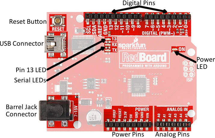
Supplying Power
The RedBoard can be powered via either the USB or barrel jack connectors. If you choose to power it via USB, the other end of the USB cable can be connected to either a computer or a (5V regulated) USB wall charger.
The power jack accepts a center-positive barrel connector with an outer diameter of 5.5mm and inner diameter of 2.1mm. Our 9V and 12V adapters are good choices if you're looking to power the RedBoard this way. Any wall adapter connected to this jack should supply a DC voltage between 7 and 15V.
USB is usually the easiest way to power the board, especially when you're programming it, because the USB interface is required for uploading code too. Why would you use the barrel jack? Usually it's because you need more power. A USB port is usually only allowed to supply 500mA, if you need more than that a wall adapter may be your only choice.
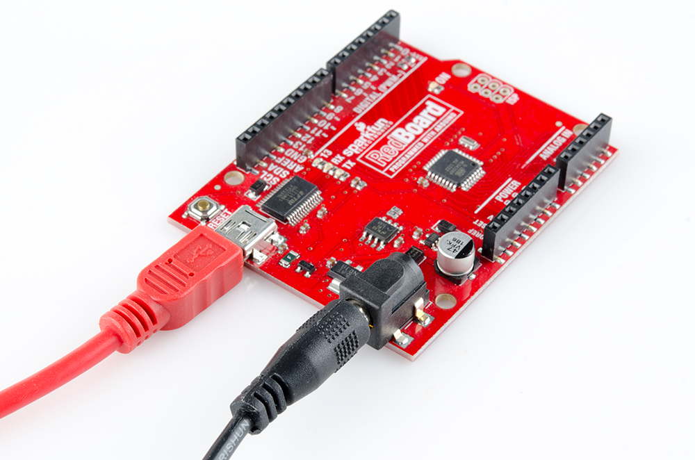
It is acceptable to connect both a barrel jack and a USB connector at the same time. The RedBoard has power-control circuitry to automatically select the best power source.
Using the RedBoard Headers
All of the RedBoard's pins are broken out to 0.1"-spaced female headers (i.e. connectors) on the outer edges of the board. Most pins are arranged into logical collections -- there are headers dedicated to power inputs/outputs, analog inputs, and digital inputs.
The digital pins are the digital inputs and outputs of the Arduino. These are what you connect to buttons, LEDs, sensors, etc. to interface the Arduino with other pieces of hardware. Pins marked with a tilde (~) can also serve as analog outputs, which you can use to dim LEDs or run servo motors.
There are six analog inputs on the analog header. These pins all have analog-to-digital converters, which can be used to read in an analog voltage between 0 and 5V. These are useful if you need to read the output of a potentiometer or other analog sensors. All six analog pins can also serve as digital inputs and outputs.
The power header is mostly full of voltage supply pins. These pins are traditionally used as power sources for other pieces of hardware (like LEDs, potentiometers, and other circuits). The '3.3V' and '5V' pins are regulated 3.3V and 5V voltage sources. The 'GND' pins are the common ground -- the 0V reference for those voltage supplies. 'VIN' is the input voltage, it'll be equal to the voltage of your input supply if you have a wall adapter connected. If nothing is connected to the barrel jack, and you're powering the board via USB, VIN should be around 5V.
Connecting to the Headers
There are a variety of wires, connectors, and other items that can be inserted into these headers to interface with the Arduino. Jumper wires are a good option, if you want to connect the RedBoard up to other pieces of circuitry that may live on a breadboard.

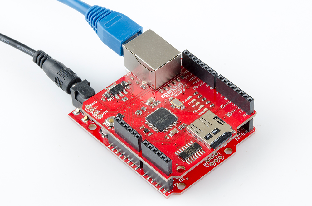
Arduino shields are another popular way to interface with the RedBoard connectors. These Arduino-shaped boards piggyback onto the RedBoard, and connect to all four headers at once. Shields exist in hundreds of forms, they can add GPS, WiFi, MP3 decoding, and all sorts of other functionality to your Arduino.
And there are plenty of other interfacing options too. If you have a 0.1"-spaced connector, like a Molex, you can plug that right in. Or just strip and cut some wire.
Download/Install Arduino
Before you plug the RedBoard into your computer, you'll need to install Arduino first.
Installing Arduino
To begin, head over to Arduino's download page and grab the most recent, stable release of Arduino. Make sure you grab the version that matches your operating system.
Download Arduino!
The installation procedure is fairly straightforward, but it varies by OS. Here are some tips to help you along. We've also written a separate Installing Arduino tutorial if you get really stuck.
Windows Install Tips
The Windows version of Arduino is offered in two options: an installer or a zip file. The installer is the easier of the two options, just download that, and run the executable file to begin installation. If you're prompted to install a driver during installation, select "Don't Install" (the RedBoard doesn't use the same drivers). Don't forget which directory it installs to (defaults to "Program Files/Arduino").
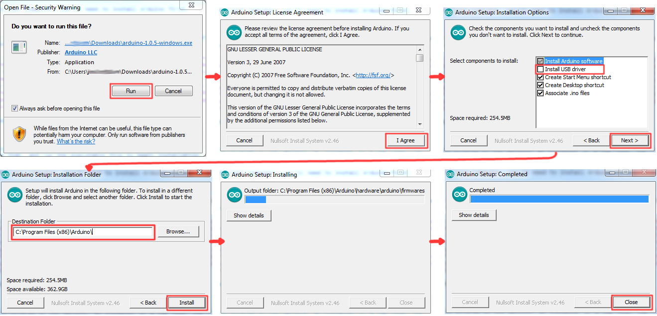
If, instead, you choose to download the zip file version of Arduino, you'll need to extract the files yourself. Don't forget which folder you extract the files into! We'll need to reference that directory when we install drivers.
Mac Install Tips
The Mac download of Arduino is only offered in a zip file version. After the download is finished, simply double-click the .zip file to unzip it.
Following that, you'll need to copy the Arduino application into your applications folder to complete installation.
Linux Install Tips
As you Linux users are no doubt aware, there are many flavors of Linux out there, each with unique installation routines. Check out the Linux section of the Installing Arduino tutorial for some helpful links for an assortment of Linux distributions.
For Ubuntu and Debian users, installing Arduino should be as easy as running a little "apt-get" magic, with a command like:
sudo apt-get update && sudo apt-get install arduino arduino-core
And other Linux distros aren't too dissimilar from that.
With Arduino downloaded and installed, the next step is to plug the RedBoard in and install some drivers! Pretty soon you'll be blinking LEDs, reading buttons, and doing some physical computing!
Install FTDI Drivers
Once you have downloaded and installed Arduino, it's time to connect the RedBoard to your computer! Before you can use the board, though, you'll need to install drivers.
Windows Driver Installation
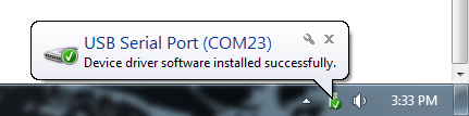
After initially plugging your RedBoard in, your computer will try to search for a compatible driver. It may actually succeed! The FTDI drivers are pretty common, so Windows Update may know a little something about them. If the drivers do automatically install, you should see a little bubble notification saying so:
If your computer failed to find drivers, we'll have to install them manually. Check out our Windows FTDI Driver Install guide for driver install instructions.
Mac Driver Installation
If you're lucky, the FTDI drivers should automatically install on Mac OS X, otherwise you'll have to manually install the drivers. Check out the Mac FTDI Driver Installation guide for help installing the drivers.
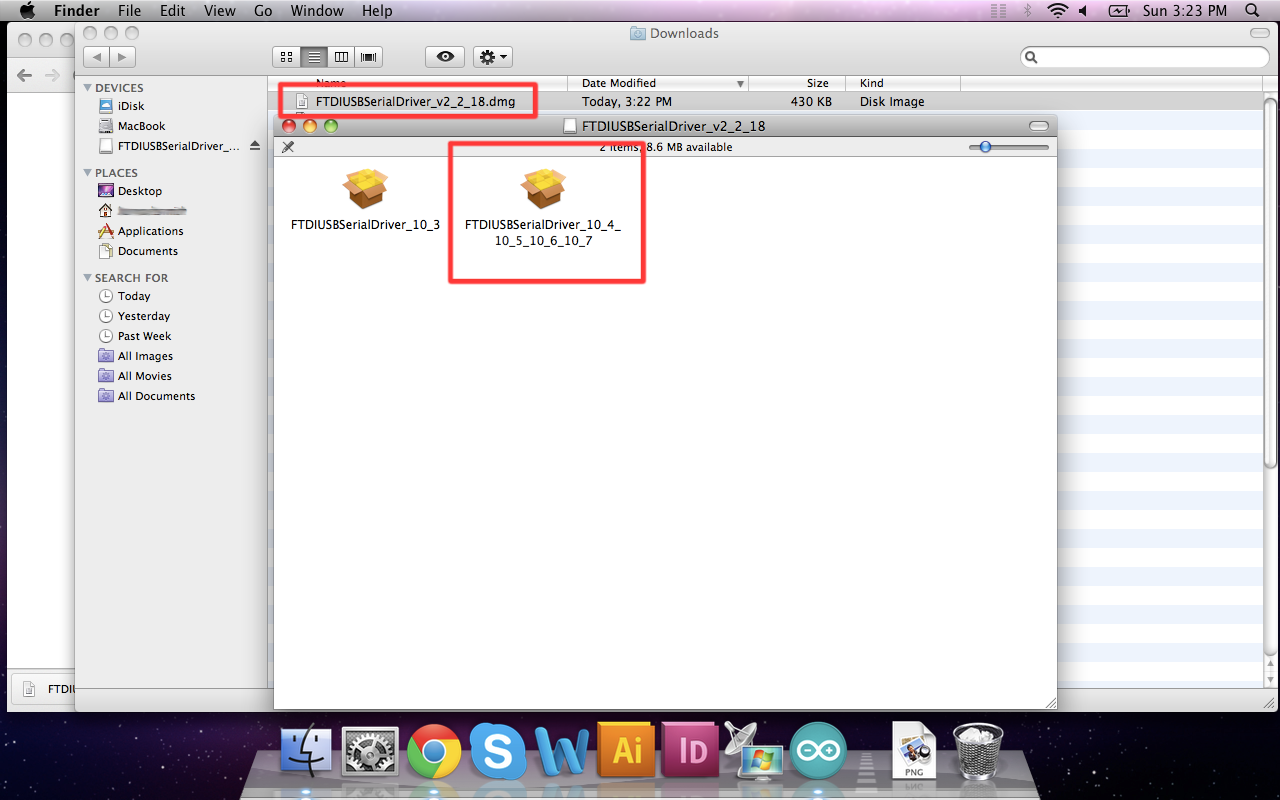
In short, the process involves heading over to the FTDI driver website, and downloading the most up-to-date VCP drivers. Then you'll simply run the "FTDIUSBSerialDriver_v2_2_18.dmg" file you downloaded, and follow the installation prompts.
Linux Driver Installation
Linux is actually pretty good about automatically installing the drivers. If you have any trouble, check out our Linux FTDI Driver guide.
Now it's time to breathe easy! You'll only have to run through this driver installation process once, the first time you connect the board to your computer. Now it's time to upload a sketch!
Uploading Blink
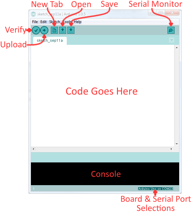
Now it's finally time to open up the Arduino software. You'll be presented with a window that looks a little something like this:
Lets upload a Blink sketch to make sure our new RedBoard setup is totally functional. Go up to the File menu in Arduino, then go to Examples > 01.Basics > Blink to open it up.
Before we can send the code over to the RedBoard, there are a couple adjustments we need to make.
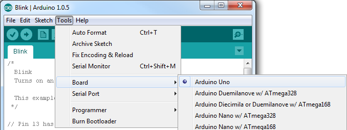
Select a Board
This step is required to tell the Arduino IDE which of the many Arduino boards we have. Go up to the Tools menu. Then hover over Board and make sure Arduino Uno is selected.
Select a Serial Port
Next up we need to tell the Arduino IDE which of our computer's serial ports the RedBoard is connected to. For this, again go up to Tools, then hover over Serial Port and select your RedBoard's COM port.
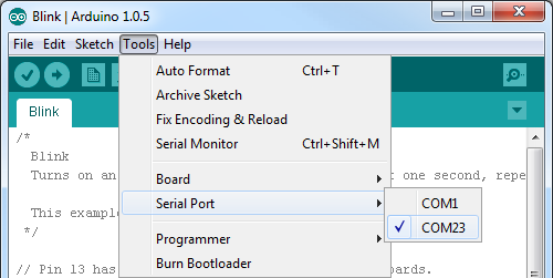
If you've got more than one port, and you're not sure which of the serial ports is your RedBoard, unplug it for a moment and check the menu to see which one disappears.
Upload!
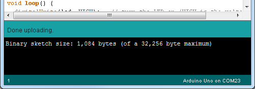
With all of those settings adjusted, you're finally ready to upload some code! Click the Upload button (the right-pointing arrow) and allow the IDE some time to compile and upload your code. It should take around 10-20 seconds for the process to complete. When the code has uploaded, you should see something like this in your console window:
And if you look over to the RedBoard, you should see the blue LED turn on for a second, off for a second, on for a second, off for a second...ad infinitum (at least until it loses power). If you want to adjust the blink speed, try messing with the "1000" value in the delay(1000); lines. You're well on your way to becoming an Arduino programmer!
Something Wrong?
Uh oh! If you didn't get a "Done Uploading" message, and instead got an error, there are a few things we can double-check.
If you got an avrdude: stk500_getsync(): not in sync: resp=0x00 error in your console window.
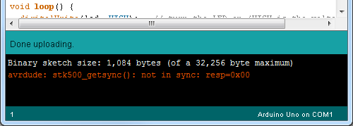
Either your serial port or board may be incorrectly set. Again, make sure Arduino Uno is the board selection (under the "Tools > Board" menu). The serial port is usually the more common culprit here. Is the Serial Port correctly set (under the "Tools > Serial Port" menu)? Did the drivers successfully install? To double check your RedBoard's serial port, look at the menu when the board is plugged in, then unplug it and look for the missing port. If none of the ports are missing, you may need to go back to driver installation.
Resources and Going Further
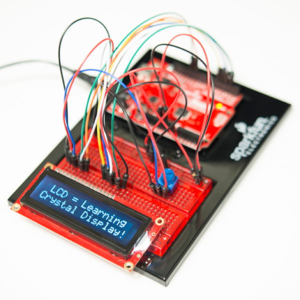
What's next? That's completely up to you! Blinking a little LED is the entry to an amazing world full of buzzers, sensors, and lots of blinky stuff. The RedBoard can interface with just about any electronic gizmo out there, like an LCD:
For more ideas, check out the SparkFun Inventor's Kit, which centers around the RedBoard, and teaches you how to connect it up to buttons, relays, flex sensors, and other components.
If you'd like to continue learning more about using Arduino, check out some of these tutorials on the subject:
- Arduino Comparison Guide
- Arduino Shields -- Arduino shields help to easily extend the capability of your Arduino. They can equip your Arduino with GPS, MP3 decoding, wireless communication, and much more!
- Data Types in Arduino -- This more advanced tutorial examines the various data types usable in Arduino.
- Connecting Arduino to Processing -- Learn how to send serial data from Arduino to your computer and visualize it graphically using Processing.