ESP8266 Powered Propane Poofer
 Nick Poole
 Introduction
Is there anything more fun to look at than a big (controlled) fire? For most of history, pyrotechnic effects have been adding an edge to everything from the Olympic games to the KISS Reunion Tour (surely, these are defining moments in the history of man) But while the ancient Greeks preferred to light their fires with an exhausted, torch-bearing athlete, I'm much more interested in lighting fires from the comfort of my sofa. Enter: The ESP8266 Thing Dev Board. Now we're cookin' with gas...

Required Materials
Along with all the components necessary to build the propane poofer (discussed later), you will also need the following electronics to replicate this project:
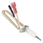
Silicon Nitride Igniter - 12V
COM-11694Suggested Reading
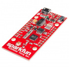
If you have not worked with the ESP8266 before this project, we highly recommend reading our ESP8266 Thing Dev Board Hookup Guide before tackling this project.
ESP8266 Thing Development Board Hookup Guide
Flame Throwing 101
Propane poofers are a comprehensively solved engineering problem. A quick Google search reveals more designs for propane-powered flame effects than you can shake a stick at. It also becomes apparent, in short order, that the Burning Man festival attracts quite the collection of semi-professional pyros. Browsing these designs, I've found that while there are a lot of variations, the basic structure of a propane poofer stays fairly constant:
This is the go-to design for propane flame-cannons, the so-called "accumulator cannon". In an accumulator cannon, a fuel source is regulated to a relatively low pressure and fed into accumulator tanks (often, they're modified propane cylinders). These accumulators allow several cannons to be fed from one large gas source. Each cannon has a pilot on a low pressure regulator which burns constantly to provide a source of ignition when it's time to make a fireball. When the time comes, the solenoid valve at the end of the accumulator is opened, allowing the accumulator to empty through the barrel and be ignited by the pilot. Because the accumulator was allowed to pressurize, you can fire multiple accumulator cannons on the same tank simultaneously without worrying about a big pressure drop in the system.
Because I was building a single portable cannon, I decided to modify this design a little bit. Here's what I came up with:
My fuel source would be a pair of disposable propane cylinders, like the kind used in camping stoves and torches. These are small, lightweight and inexpensive... plus, I could buy them by the armful at my local hardware supply. Two such tanks would feed my cannon. Once I had decided on the gist of my design, I started shopping for parts...
Building the Poofer
Between Amazon and the hardware store, I was able to put together the following parts list:
From the hardware store plumbing section
- 2"x12" Threaded Pipe Nipple
- 2" Coupler (x2)
- 2"x1" Bushing (x2)
- 1" Threaded Pipe Nipple (x2)
- 1"x1/2" Reducer
- 1/2" Threaded Pipe Nipple
- 1/2"x1/4" Reducer
- 1/4" Threaded Pipe Nipple
- 1 1/4" Reducer
- 1/4" Threaded Plug
From various Amazon sellers
- 1/4" FFF Brass Tee
- 1/4" MMM Brass Tee
- 1/4" Solenoid Valve (x2)
- 1/4" Brass Gas Bottle Adapter
With all of the parts collected, it's time to assemble the cannon! Here are a few exploded diagrams (no pun intended) to detail how everything fits:
As you can see, I built the expansion chamber by using a series of reducer fittings to connect a foot-long section of 2" pipe to the outlet of the gas bottles. I replaced the pilot with an electrical ignitor, eliminating the need for a low pressure regulator and a separate fuel line. I also decided to move the solenoid valves to the section before the tee junction allowing me to individually open each bottle to the expansion chamber. Let's have a closer look at this tee junction:
You may wonder why I included a female tee between the expander and the male tee only to plug the unused port. Originally, there was a large solenoid valve on the output end of the cannon, allowing the expander to be used as an accumulator. I had a 1/4" pressure transducer threaded into that port to monitor the interior pressure of the expansion chamber. It turned out that bringing the expander up to tank pressure and purging it through a 1" solenoid was not only deafeningly loud but generated a stream of uncarborated gas that was nearly impossible to light reliably. When I removed the big solenoid valve, I also removed the pressure transducer (as that section of the cannon became open to atmosphere).
The nozzle end of the cannon is designed to encourage the escaping gas to spread and mix with the surrounding air. I drilled a hole in the side of the reducer fitting in order to secure the Silicon Nitride Ignitor. The leads for the ignitor run down the side of the expansion chamber where they're wrapped in heat tape to protect them from the fire.
Because this cannon doesn't have a pilot, it's necessary to give a short burst from one tank into the expansion chamber in order to start an open flame at the end of the barrel. As gas slowly leaks from the expander through the nozzle and carborates near the ignitor, it will maintain a low flame. When it's time to fire a big poof, you simply open both bottles to the chamber for about half a second and whoosh!
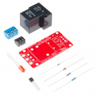
Wire it up
If the propane bottles are the heart of this operation then the ESP8266 Thing is definitely the brains. The Thing board will allow us to connect to the flame cannon and fire it from a safe distance. Because the Thing can't source anywhere near the voltage or current necessary to fire the solenoid valves or light the igniter, we'll switch them using our Beefcake Relay kits. Our 12VDC power source needs to be portable, rechargable and capable of supplying a decent amount of current so I used a sealed lead-acid battery for a home alarm system. You can pick these up at most home improvement stores.
Here's what the whole project looks like once it's wired up:
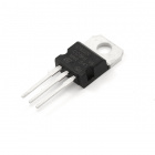
For this project, an SLA battery was used as the power supply for the entire rig. However, the ESP8266 Thing Dev Board has a VIN tolerance of 3.3V and 6V. I DO NOT recommend powering your Thing Dev Board with the unregulated 12V. A 5V source was needed to properly power the Thing Dev Board as well as fire the relays. I sloppily wired in a 5V regulator which provided plenty of power at 5V to effectively switch the Beefcake Relays. Each relay's signal line was connected to a GPIO pin on the Thing, I chose 4, 0 and 13 only because they're side-by-side. Finally, the high side of the 12V line is switched by each relay before reaching the igniter and the two solenoid valves.
In order to recharge the SLA battery, I just throw it on my bench supply at about 14V until it stops drawing current. There are fancier ways to do this, but I'm happy with my system. I didn't find an external antenna necessary for the Thing to work at significant range thanks to the on-board trace antenna. If you want extra range, however, you can cut the antenna trace, add a U.fl to RP-SMA pigtail and screw on one of our big rubber duck antennas.
To keep the electronics safe and dry, I put them in a plastic ammunition box that I picked up at the hardware store. A bundle of cables comes through a hole in the side of the box and connects to the cannon. The whole unit doesn't weigh too much, and you can lean the cannon against the box to stabilize it.
Programming the Thing
The firmware that we're using for the Thing board is based on the AP Web Server example code. This example code sets the Thing board up as a wireless access-point and serves a simple webpage to any connected client. Most of the magic is in the ESP8266WiFi library, so the sketch itself isn't very long at all. Let's take a look at it:
language:c

#include <ESP8266WiFi.h>

//////////////////////
// WiFi Definitions //
//////////////////////
const char WiFiAPPSK[] = "sparkfun";

/////////////////////
// Pin Definitions //
/////////////////////
const int VENT1_PIN = 4; //
const int VENT2_PIN = 0; //
const int IGNITION_PIN = 13; //

WiFiServer server(80);

void setup()
{
  initHardware();
  setupWiFi();
  server.begin();
}

void loop()
{
  // Check if a client has connected
  WiFiClient client = server.available();
  if (!client) {
    return;
  }

  // Read the first line of the request
  String req = client.readStringUntil('\r');
  Serial.println(req);
  client.flush();

  // Match the request
  int val = -1;
  if (req.indexOf("/vent1/1") != -1)
    val = 0;
  else if (req.indexOf("/vent2/1") != -1)
    val = 2;
  else if (req.indexOf("/vent_all/1") != -1)
    val = 3;
  else if (req.indexOf("/ignition/1") != -1)
    val = 4;
  else if (req.indexOf("/ignition/0") != -1)
    val = 5;

  // Set GPIO according to the request

  if (val == 0){
    digitalWrite(VENT1_PIN, 1);
    delay(500);
    digitalWrite(VENT1_PIN, 0);}

  else if (val == 2){
    digitalWrite(VENT2_PIN, 1);
    delay(500);
    digitalWrite(VENT2_PIN, 0);}

  else if (val == 3){
    digitalWrite(VENT1_PIN, 1);
    digitalWrite(VENT2_PIN, 1);
    delay(500);
    digitalWrite(VENT1_PIN, 0);
    digitalWrite(VENT2_PIN, 0);}

  else if (val == 4){
    digitalWrite(IGNITION_PIN, 1);}

  else if (val == 5){
    digitalWrite(IGNITION_PIN, 0);}

  client.flush();

  // Prepare the response. Start with the common header:
  String s = "HTTP/1.1 200 OK\r\n";
  s += "Content-Type: text/html\r\n\r\n";
  s += "<!DOCTYPE HTML>\r\n<html>\r\n";

  if ( digitalRead(IGNITION_PIN) == 0 ){
  s += "Ignitior is currently turned OFF.";}
  else{
  s += "Ignitior is currently turned ON.";}
  s += "<br><br>\r\n"; // Go to the next line.

  s += "<a href = \"/ignition/1\">Glow Ingition On</a><br>\r\n";
  s += "<a href = \"/ignition/0\">Glow Ingition Off</a><br>\r\n";
  s += "<a href = \"/vent1/1\">Vent Tank 1 (500ms)</a><br>\r\n";
  s += "<a href = \"/vent2/1\">Vent Tank 2 (500ms)</a><br>\r\n";
  s += "<a href = \"/vent_all/1\">Vent Both Tanks (500ms)</a><br>\r\n";

  s += "</html>\n";

  // Send the response to the client
  client.print(s);
  delay(1);
  Serial.println("Client disonnected");

  // The client will actually be disconnected
  // when the function returns and 'client' object is detroyed
}

void setupWiFi()
{
  WiFi.mode(WIFI_AP);

  // Do a little work to get a unique-ish name. Append the
  // last two bytes of the MAC (HEX'd) to "Thing-":
  uint8_t mac[WL_MAC_ADDR_LENGTH];
  WiFi.softAPmacAddress(mac);
  String macID = String(mac[WL_MAC_ADDR_LENGTH - 2], HEX) +
                 String(mac[WL_MAC_ADDR_LENGTH - 1], HEX);
  macID.toUpperCase();
  String AP_NameString = "ESP8266 Flame Cannon " + macID;

  char AP_NameChar[AP_NameString.length() + 1];
  memset(AP_NameChar, 0, AP_NameString.length() + 1);

  for (int i=0; i<AP_NameString.length(); i++)
    AP_NameChar[i] = AP_NameString.charAt(i);

  WiFi.softAP(AP_NameChar, WiFiAPPSK);
}

void initHardware()
{
  Serial.begin(115200);
  pinMode(VENT1_PIN, OUTPUT);
  digitalWrite(VENT1_PIN, LOW);
  pinMode(VENT2_PIN, OUTPUT);
  digitalWrite(VENT2_PIN, LOW);
  pinMode(IGNITION_PIN, OUTPUT);
  digitalWrite(IGNITION_PIN, LOW);

}
Because this code is essentially an expanded version of the example code, I won't dive into it too deeply here. That being said, let's look at what's changed:
Matching Requests
While the example code was only looking for 3 possible valid requests, we'll be looking for any of 5: Ignition On, Ignition Off, Vent Tank 1, Vent Tank 2 and Vent All. We handle these requests by assigning a value to each like this:
language:c
  if (req.indexOf("/vent1/1") != -1)
    val = 0;
  else if (req.indexOf("/vent2/1") != -1)
    val = 2;
  else if (req.indexOf("/vent_all/1") != -1)
    val = 3;
  else if (req.indexOf("/ignition/1") != -1)
    val = 4;
  else if (req.indexOf("/ignition/0") != -1)
    val = 5;
When we send our response, we'll include hyperlinks for each of these requests.
Setting the GPIO
language:c
 if (val == 0){ // Vent Tank 1
    digitalWrite(VENT1_PIN, 1);
    delay(500);
    digitalWrite(VENT1_PIN, 0);}

  else if (val == 2){ // Vent Tank 2
    digitalWrite(VENT2_PIN, 1);
    delay(500);
    digitalWrite(VENT2_PIN, 0);}

  else if (val == 3){ // Vent All
    digitalWrite(VENT1_PIN, 1);
    digitalWrite(VENT2_PIN, 1);
    delay(500);
    digitalWrite(VENT1_PIN, 0);
    digitalWrite(VENT2_PIN, 0);}

  else if (val == 4){ // Ignition On
    digitalWrite(IGNITION_PIN, 1);}

  else if (val == 5){ // Ignition Off
    digitalWrite(IGNITION_PIN, 0);}
Each valid request has an associated GPIO call to open or close a relay. The "Vent Tank" requests simply close the relay for half a second, and then release it. Requests made to the ignitor set it to either the on or off position until further notice.
Formulating a Reply
Our server's reply will always be a list of hyperlinks that make it easy to quickly fire valid requests. At the top of the list, we'll add an indicator to let us know whether we have the ignitor turned on. Each line of the html response is appended to a string object and sent to the server library to be relayed to the client. The html reponse, without the weird formatting, looks like this:
  HTTP/1.1 200 OK
  Content-Type: text/html
  <!DOCTYPE HTML>

  <html>

  Ignitior is currently turned ON.<br>
  <a href = "/ignition/1">Glow Ingition On</a><br>
  <a href = "/ignition/0">Glow Ingition Off</a><br>
  <a href = "/vent1/1">Vent Tank 1 (500ms)</a><br>
  <a href = "/vent2/1">Vent Tank 2 (500ms)</a><br>
  <a href = "/vent_all/1">Vent Both Tanks (500ms)</a><br>

  </html>
Make Fire!
This thing is ready to breathe fire! But first, a checklist:
- Make sure your propane bottles are securely connected.
- Listen for possible leaks.
- Connect the battery leads to power up the system.
- Get a safe distance away.
- Connect to the flamethrower's WiFi network on your phone or laptop.
- Navigate to 192.168.4.1/ignition/0
- Press "Glow Ignition On"
- Give the igniter a few seconds to heat up.
- Press "Vent Tank 1 (500ms)"
- Wait for a flame to start
The cannon is now lit and ready to fire. Clear the area and press "Vent All" for an awesome fireball! Be sure to give the cannon some time to rest between firings. Each time you fire the cannon, the solenoid valves are flooded with freezing cold liquid propane, and too much continuous operation can damage the valves, possibly locking them open.

Resources and Going Further
There are nearly unlimited resources online for people looking to build fire toys. Thanks to festivals like Burning Man and events like Maker Faire, there are plenty of places people can go to show off their incendiary creations, and that means a big community has grown up around them. Here are a few places worth checking out if you're interested in building pyro effects:
- Poofer Supply - Small online shop that sells bits and bobs for fire toys. Even if you'd rather shop on Amazon, it's a good place to start and find out what's available.
- Foxfur Amused Blogpost - A nice little build that I referenced while working on my poofer.
- Burning Man Fire Effects Community - Awesome Facebook group for people who like to build fire effects.
- Engineering Roundtable - With Chris Taylor's sound responsive torch!
Going Further
For more information on the Thing board and other connected projects, check out these tutorials!