LED Cloud-Connected Cloud
 Sarah Al-Mutlaq
Introduction
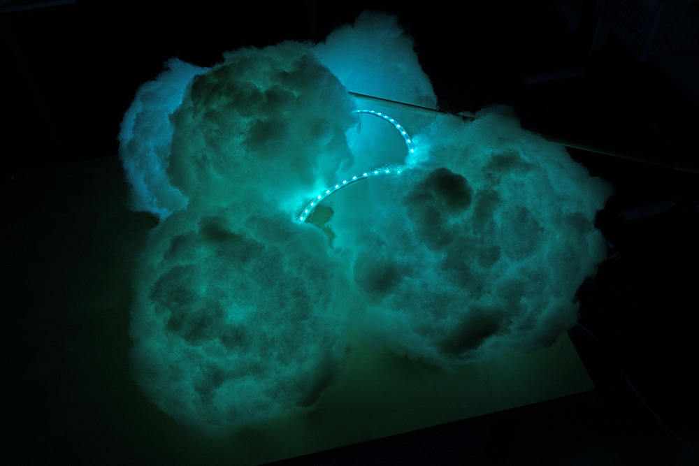
Make a rainbow LED colored cloud light that you can control from your phone. You can even have it change color based on the weather outside.

These are the clouds from episode 3 The Fellowship of the Things, which you can watch below if you haven't already.
Required Materials:
To follow along with this tutorial, you'll need the following materials.
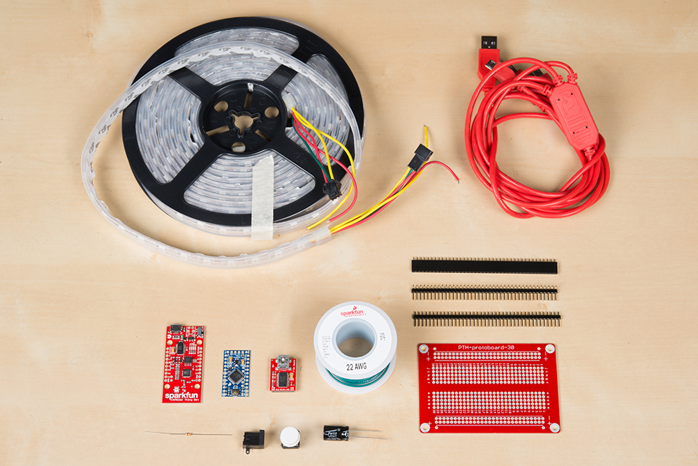
You Will Also Need
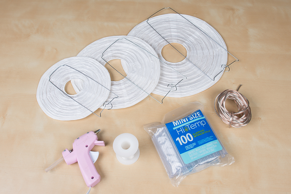
- long hook-up wire for cloud power (I used stereo wire)
- Paper lanterns (white)
- Pillow filling (I used polyfil)
- Lots of hot glue and a hot glue gun
- Fishing wire
- A wooden dowel for support
- A power source; you will need something that can put out at least 5V and 4A, but for the best results you can get a pricier 6V 8A power source.

Optional part included: Thing dev board (in the wishlist, but only needed if you want to hook up to your phone and/or weather info)
Suggested Reading:
If any of these subjects sound unfamiliar, considering reading the following tutorials before continuing on.
How to Solder: Through-Hole Soldering
Installing an Arduino Library
Installing Arduino IDE
Using the Arduino Pro Mini 3.3V
WS2812 Breakout Hookup Guide
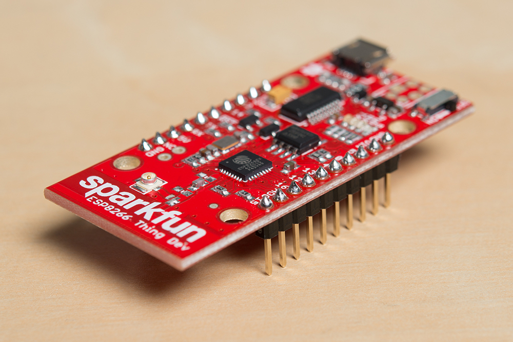
ESP8266 Thing Development Board Hookup Guide
Physical Cloud Making
We will begin by assembling the clouds.
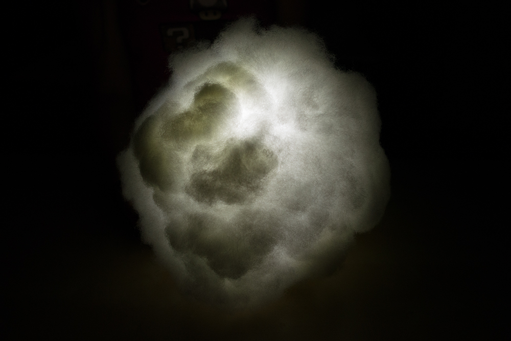
Start with an open white paper lantern, and glue on pieces of polyfil in small sections until you have covered the whole lantern.

Some tricks for making the cloud look cool when it is lit up is to swirl the polyfil before you glue it on or do other fun crazy shapes.

When you have covered it fully (don’t worry about the top and bottom holes right now), you may want to take a flashlight, and check to see what the lantern looks like when lit up. Cover any bare spots you see.
Repeat this process for as many lanterns as you would like. The more lanterns, the larger your clouds will be. Just keep in mind you'll need a power supply that can handle all the LEDs in each lantern. Paper lanterns of different sizes can create a cloud that looks more realistic.
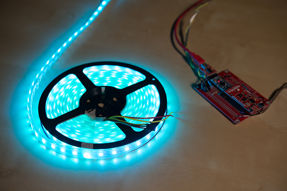
The 5m RGB LED strips fill about five lanterns, so if you want to make your cloud larger or have more than one cloud, you are going to want more RGB LED strips and power sources (you can use the same Pro Mini and ESP8266 Thing Dev Board to power multiple clouds and RGB LED strips).
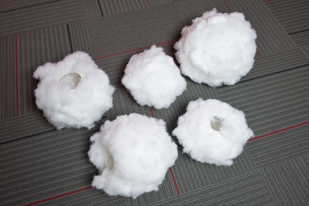
Once you have the all of your lanterns covered in polyfil, you can tie them together with the fishing wire. This was accomplished by picking a lantern that I wanted to be the highest point of the cloud and tying the tops of the other lanterns to the top of the one I chose. This will give you room for the cloud to look like it is “bobbing” and “shifting”, but if you want it to be more secure, you can tie the lanterns more tightly to each other and even tie the bottoms together as well.


Now that your lanterns are tied together, you can secure them to a wooden dowel so that the cloud is easier to transport and hang.

At this point, set your cloud up near your workstation so that you can easily install the lights and see what the cloud looks like lit up. Take this opportunity to add or take away polyfil as you see fit.
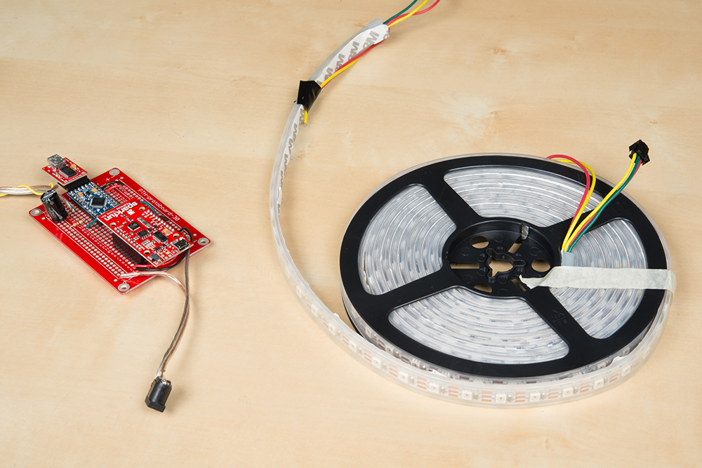
Electronics Assembly Part 1
This section will cover building the Pro Mini Circuit. We will add the Internet-connected portion in Part 2.
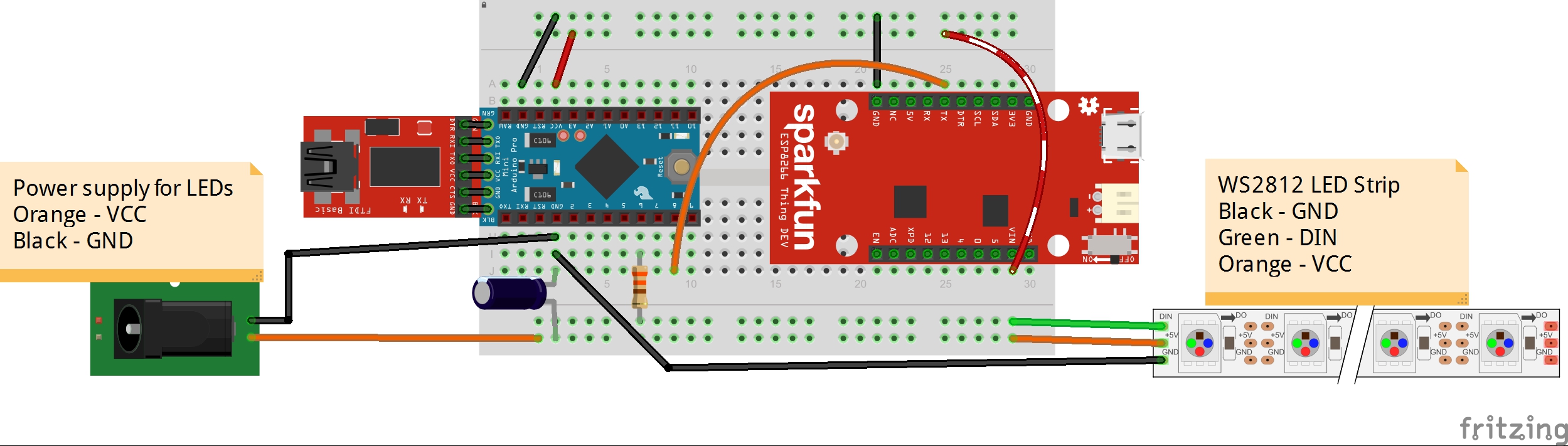
Connect the components as follows:
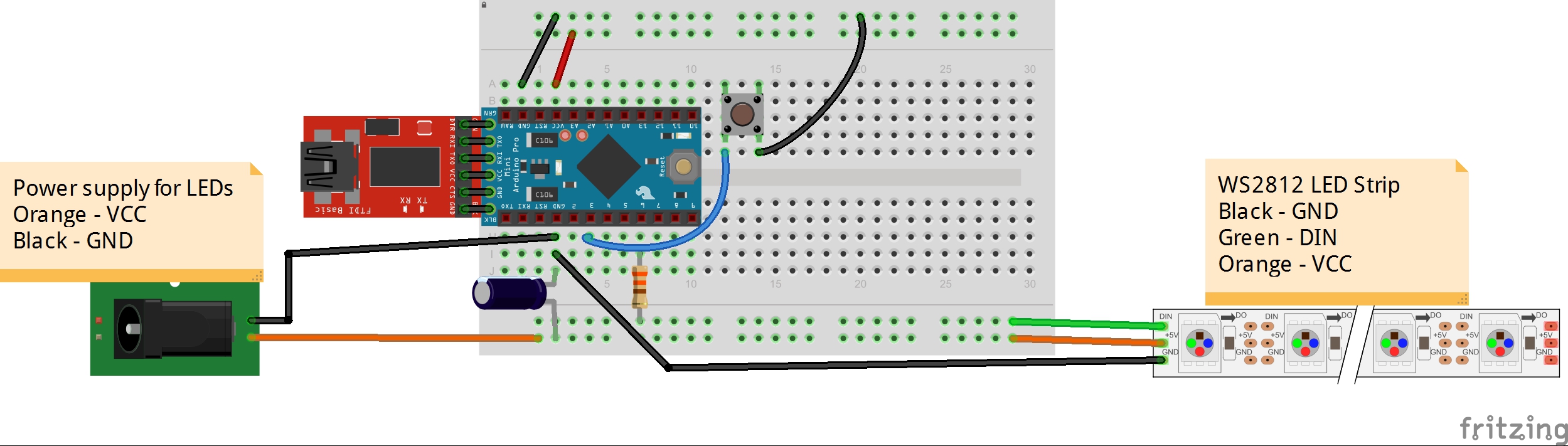
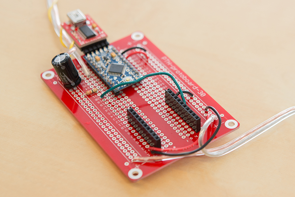
Please note that we are soldering all these components to a solderable breadboard. Feel free to build the circuit on a breadboard first to test everything out.
| Component | Breadboard | |||
|---|---|---|---|---|
| Button | j17 (To Pro Mini Pin 3) | g15 (GND) | ||
| Resistor | a22 (Pro Mini Pin 6) | Bottom - (LED Strip DIN) | ||
| Capacitor | a27 (Pro Mini GND Pin) | Bottom + (LED VCC) | ||
| Jumper Wire | Top - (GND) | i29 (Pro Mini GND Pin) | ||
| Jumper Wire | Top + | i27 (Pro Mini VCC Pin) | ||
| Jumper Wire | b25 (Pro Mini Pin 3) | f15 (button) | ||
| Jumper Wire | f13 (button) | Top - (GND) | ||
| Wire | b27 (Pro Mini GND Pin) | Ground of barrel jack | ||
| Wire | Bottom + (LED VCC) | VCC of barrel jack | ||
| Wire | c27 (Pro Mini/LED power GND Pin) | Yellow wire on LED strip (LED GND) | ||
| Wire | Bottom - (To Pro Mini Pin 6) | Green wire on LED strip (DIN) | ||
| Wire | Bottom + (LED power VCC) | Red wire on LED strip (LED VCC) | ||
* Pins not listed are not used.
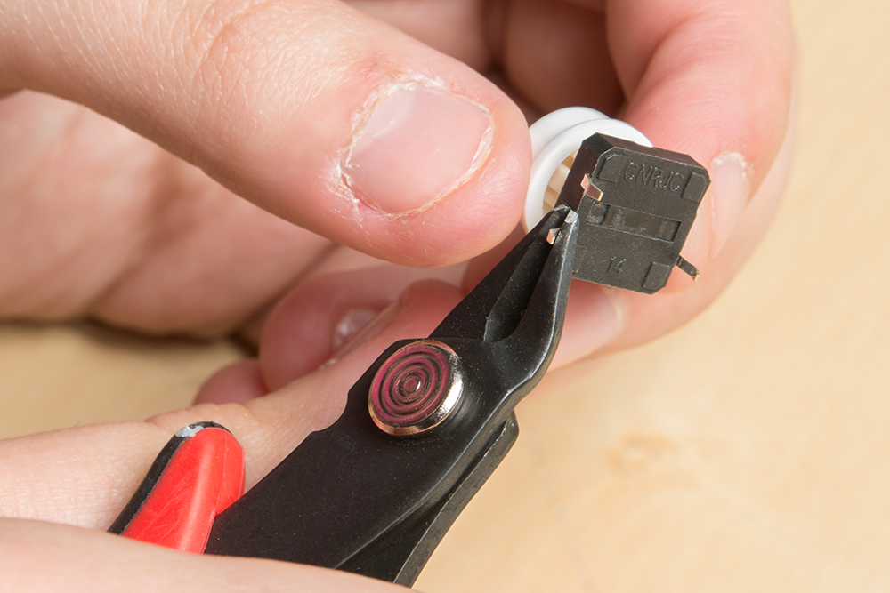
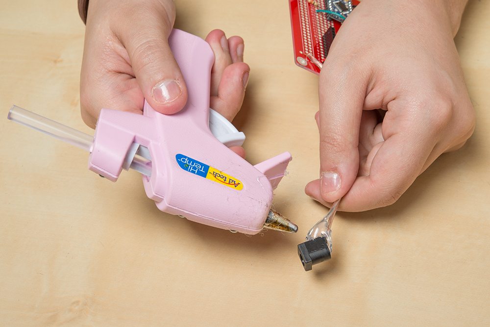
Take a button, and cut off two legs that are diagonal to each other so that it doesn't cause a short circuit.
Some things to note here is that I have put a 1000 microfarad capacitor between the LED power and ground. This is good practice, and helps distribute the current better, so that you don’t accidentally blow out your first LED. This should be done on any string of wires as a precautionary measure. I have also placed a 330Ω resistor between the DIN of the LEDs and the microcontroller. This is another good measure to protect the addressable LEDs.
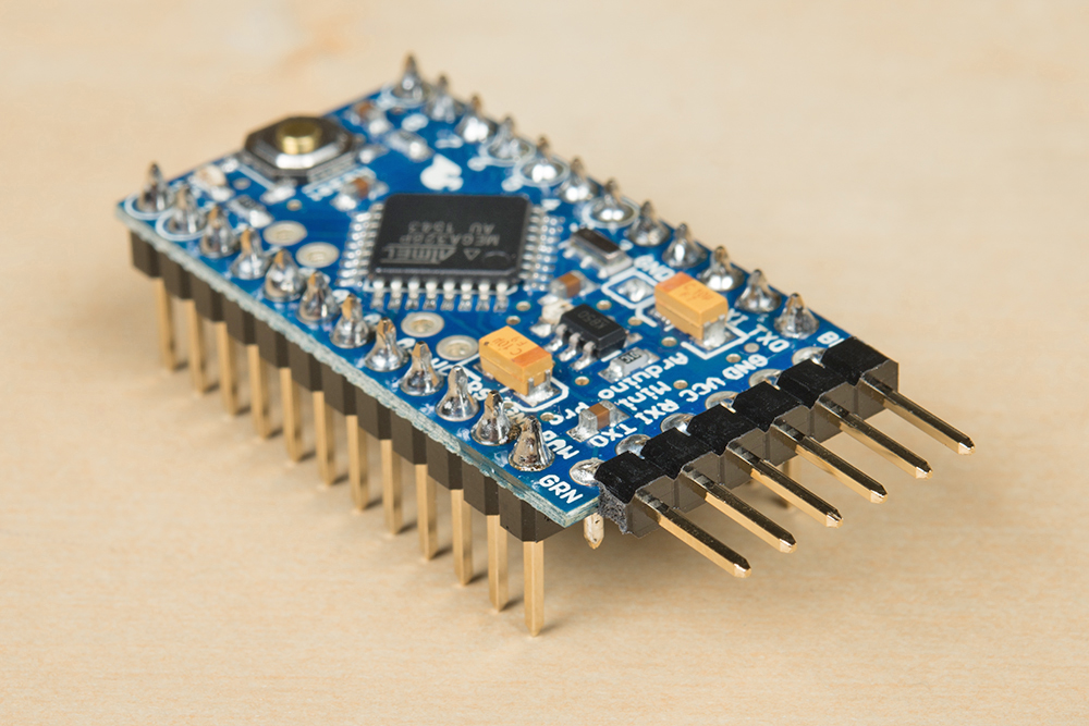
The Pro Mini will need to be powered separately from the LEDs, and this can be done through the Mini USB port of an FTDI Basic. (If you don’t want it to run off your computer you can get this USB wall charger). You can also solder wires directly to the Pro Mini's VIN pin.
Code Part 1
The following code allows you to run the lights off of the Pro Mini so that you can scroll through the different pre-programmed lighting sequences.
Note: This example assumes you are using the latest version of the Arduino IDE on your desktop. If this is your first time using Arduino, please review our tutorial on installing the Arduino IDE.
If you have not previously installed an Arduino library, please check out our installation guide.Download the most recent code from the GitHub repository:
Open the sketch titled LED_Button_Demo.ino.
Plug in the Pro Mini, choose Pro Mini as your device, select the corresponding COM port, and then click upload.
Once you have tested that your code works with your soldering job, you may want to take some hot glue and cover the wires leading to your barrel jack, just to make sure nothing shorts and to create a stronger connection.
Electronics Assembly Part 2
This section will cover adding a SparkFun thing to your project so that it can connect to the Internet.
You can keep all the soldering done in part 1, but just add a SparkFun Thing board to allow for use with your phone as well as to pull weather data.
Connect the components as follows:
| Component | Breadboard | |||
|---|---|---|---|---|
| Resistor | a22 (Pro Mini Pin 6) | Bottom - (LED Strip DIN) | ||
| Capacitor | a27 (Pro Mini GND Pin) | Bottom + (LED VCC) | ||
| Jumper Wire | Top - (GND) | i29 (Pro Mini GND Pin) | ||
| Jumper Wire | Top + (Board VCC) | i27 (Pro Mini VCC Pin) | ||
| Jumper Wire | b25 (Pro Mini Pin 3) | f15 (button) | ||
| Jumper Wire | f13 (button) | Top - (GND) | ||
| Jumper Wire | a20 (Pro Mini Pin 8) | j7 (SparkFun Thing Pin TX) | ||
| Jumper Wire | j10 (SparkFun Thing GND Pin) | Top - (GND) | ||
| Jumper Wire | a2 (SparkFun Thing VIN Pin) | Top + (Board VCC) | ||
| Wire | b27 (Pro Mini GND Pin) | Ground of barrel jack | ||
| Wire | Bottom + (LED VCC) | VCC of barrel jack | ||
| Wire | c27 (Pro Mini/LED power GND Pin) | Yellow wire on LED strip (LED GND) | ||
| Wire | Bottom - (To Pro Mini Pin 6) | Green wire on LED strip (DIN) | ||
| Wire | Bottom + (LED power VCC) | Red wire on LED strip (LED VCC) | ||
* Pins not listed are not used.
Again, same notes as part 1: adding a capacitor and resistor, and powering the Pro Mini and Thing from the wall (read part 1 for all the details).
One additional note, for ease of programming both the Pro Mini and the SparkFun Thing board, you may want to solder in female headers where the Thing board will sit and male headers to the Thing board, so that you can easily take it out to program both.
Code Part 2
Since you have two boards with microcontrollers, you will have to program each one separately.
Pro Mini Code:
If you did not do so in the previous section, download the most recent code from the GitHub repository:
Open the sketch titled LED_Control.ino.
Plug in the Pro Mini, choose Pro Mini as your device, select the corresponding COM port, and then click upload.
Blynk Setup
To hook up the Thing board to the Internet, we will be using the Blynk app. To get the code we need to program the Thing board with you will need to download the Blynk app onto your phone.
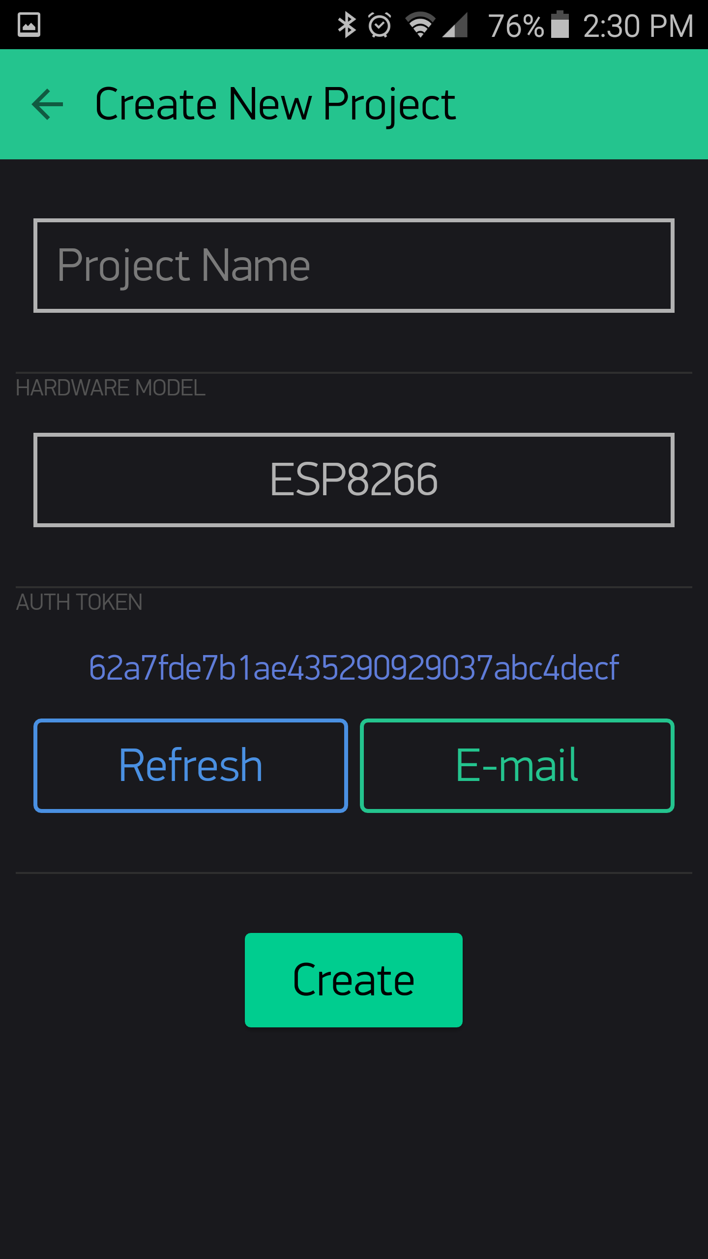
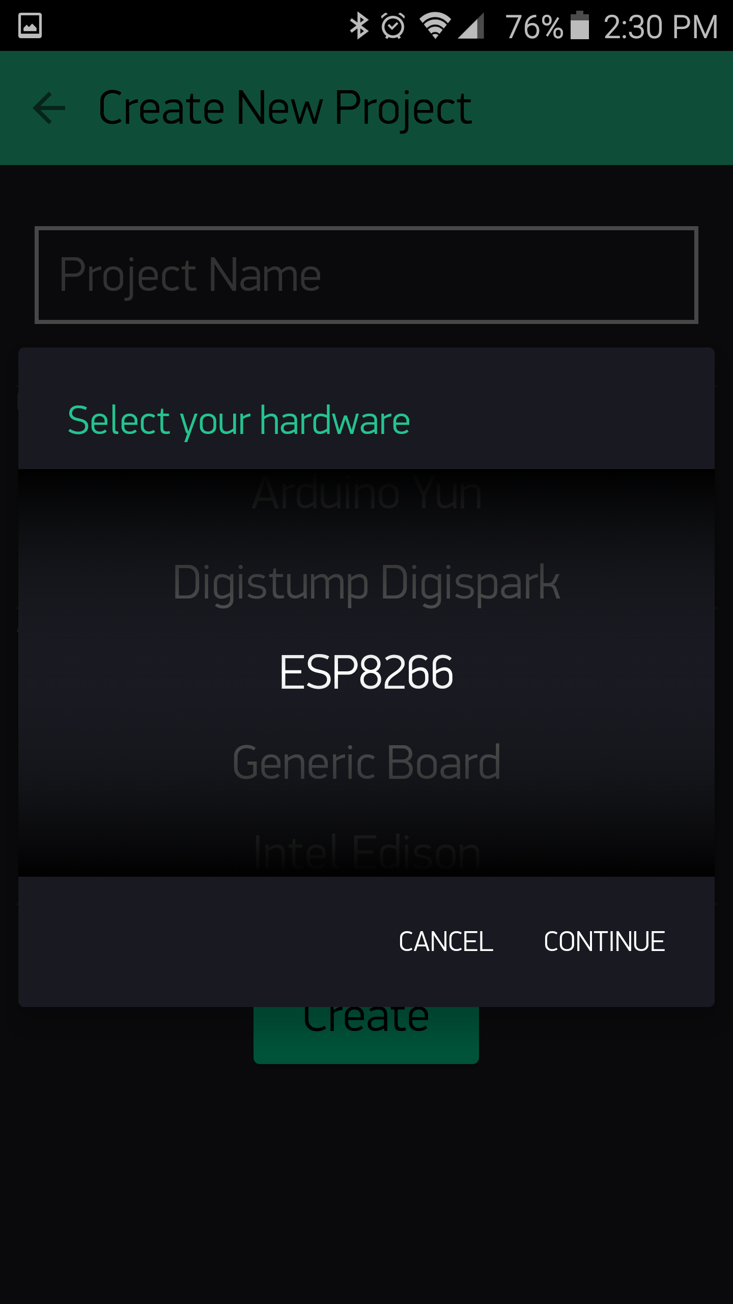
Once you have the app, create an account (if you don’t have one already), and go to “create new project”. There you can name your project, set your hardware to “ESP8266” and you can email or just copy that authentication token, which we will need to paste in the SparkFun Thing code.
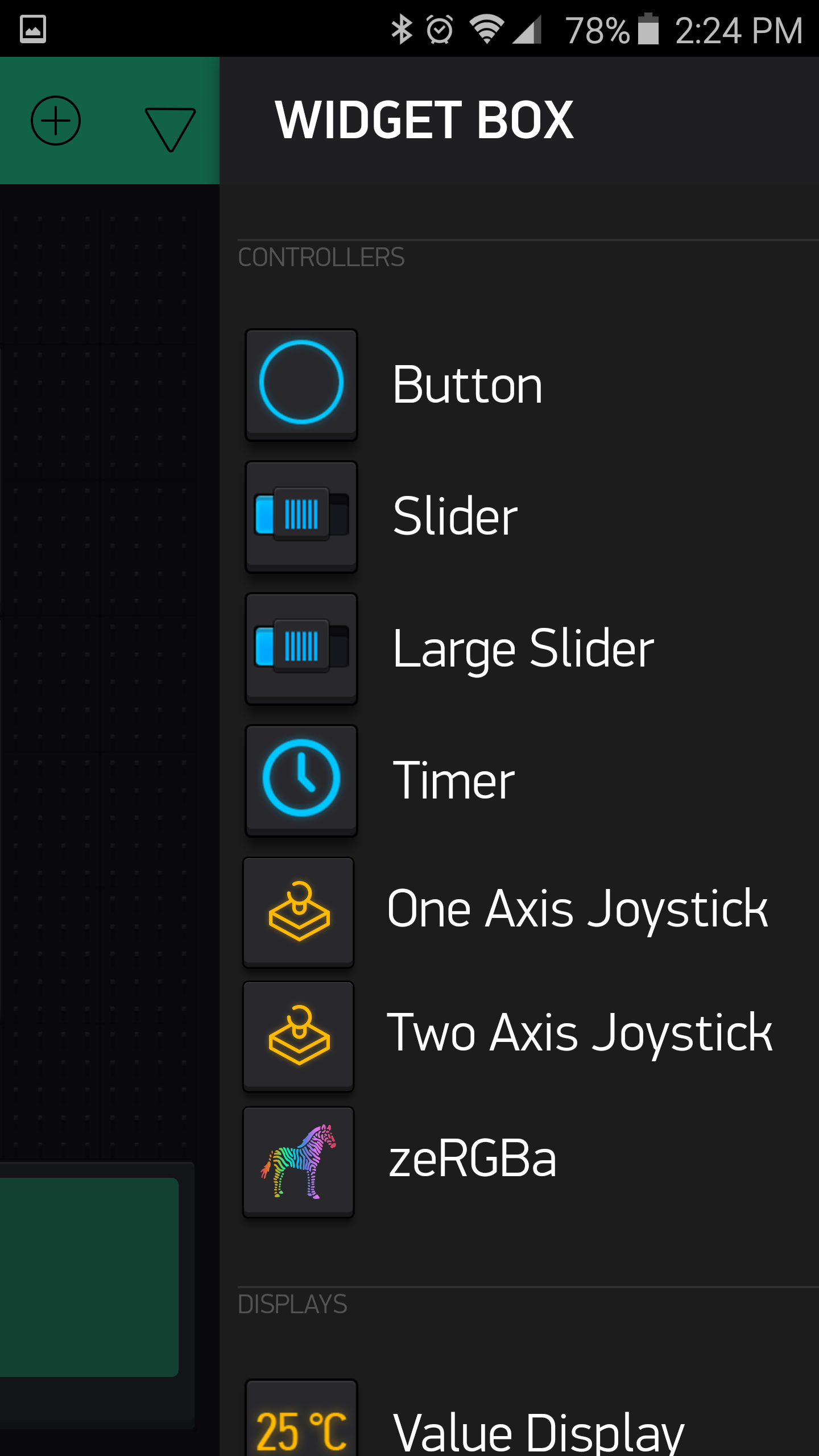
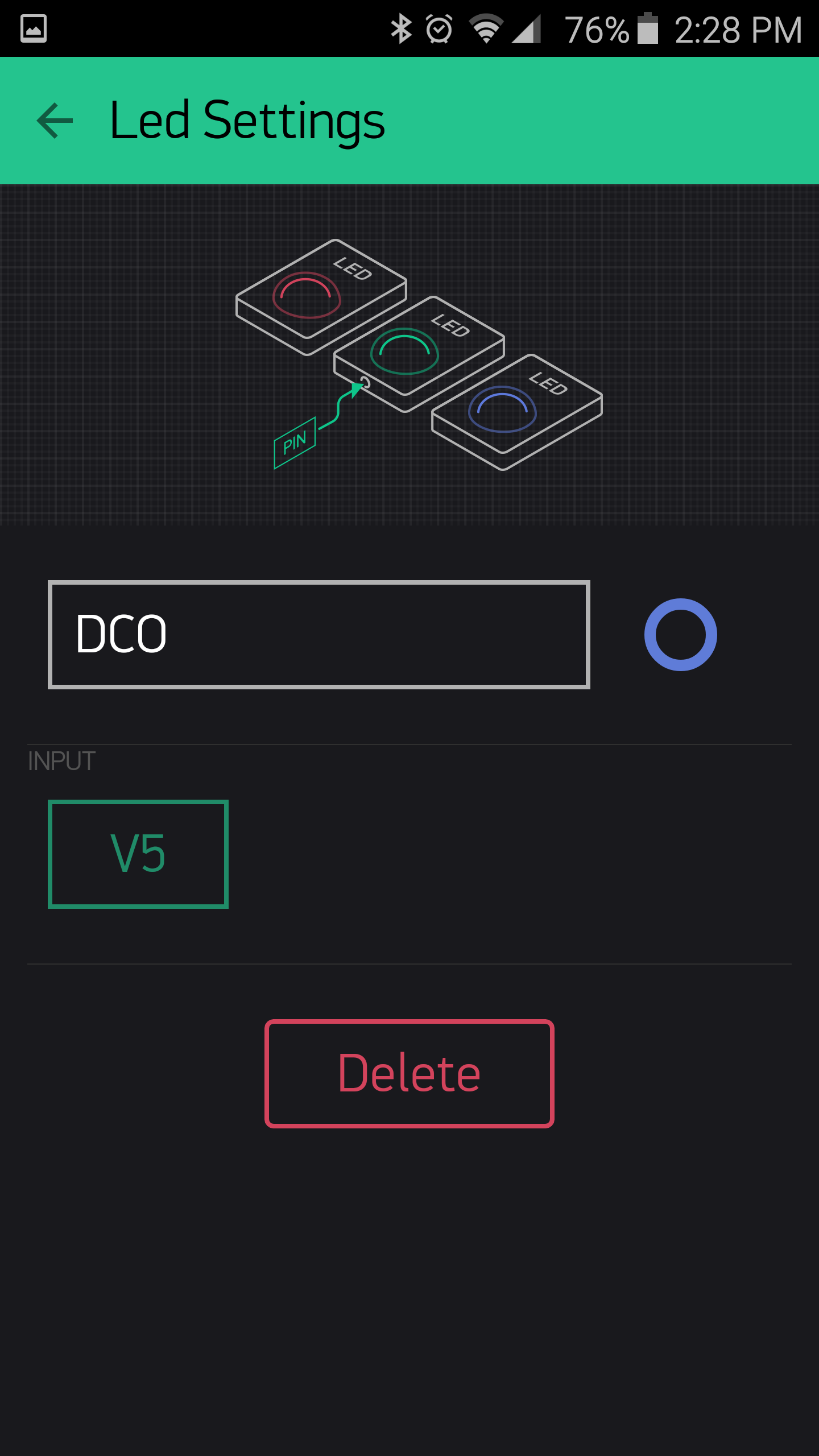
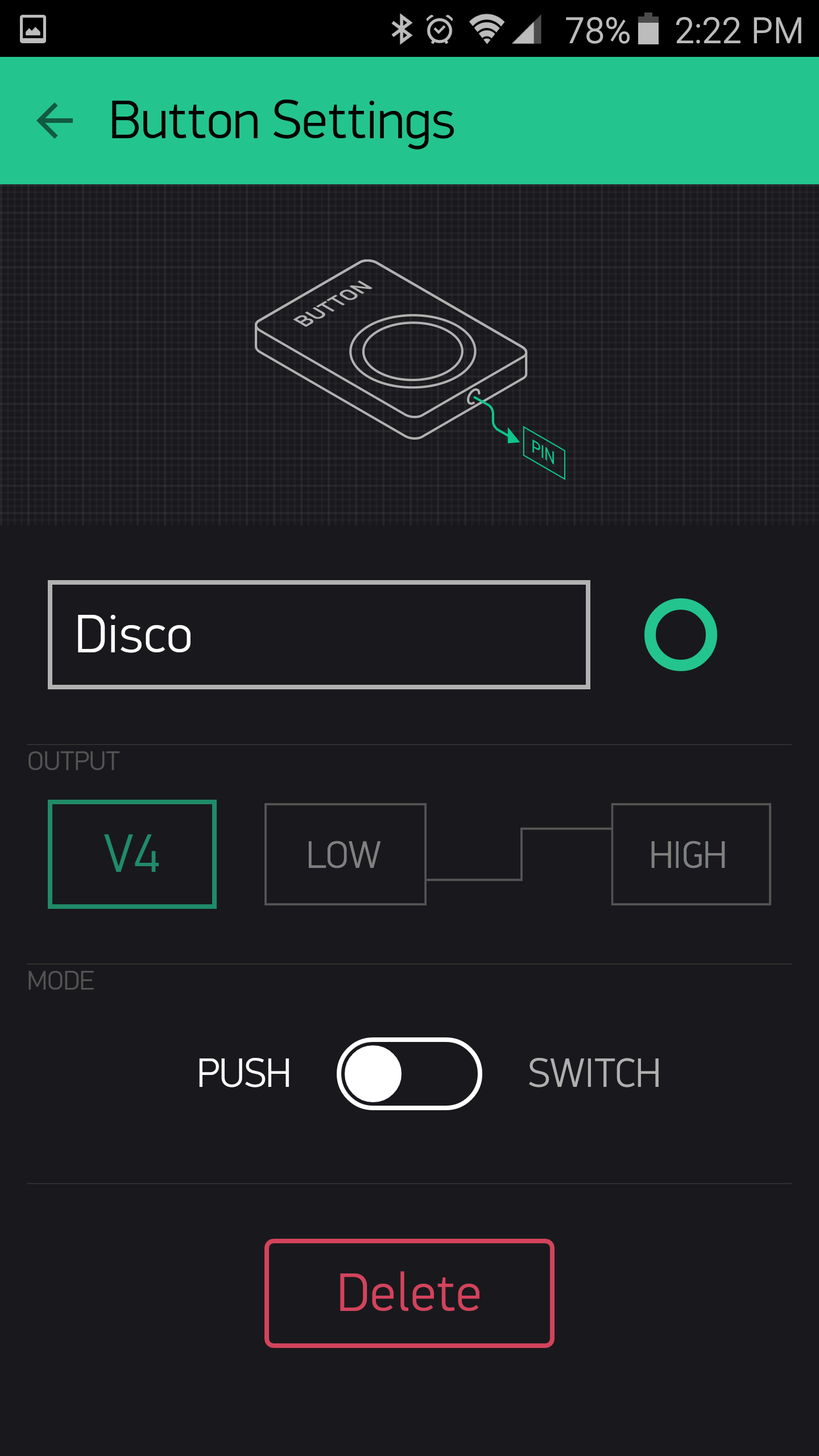
In your project that you just created, you are going to want to put three LED light widgets, three button widgets, a ZERGBA widget, and an LCD widget.
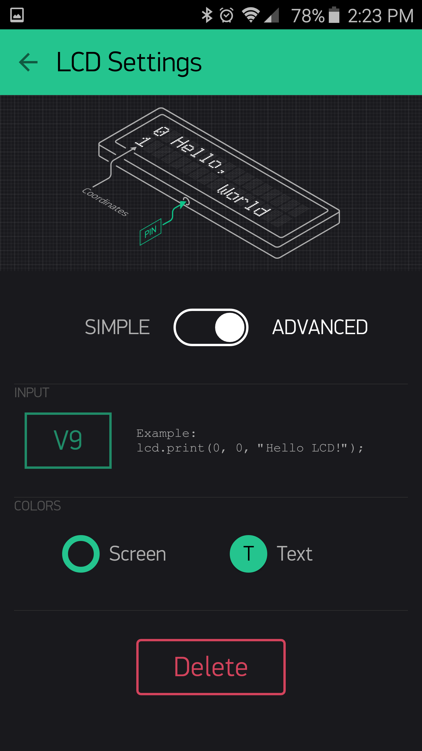
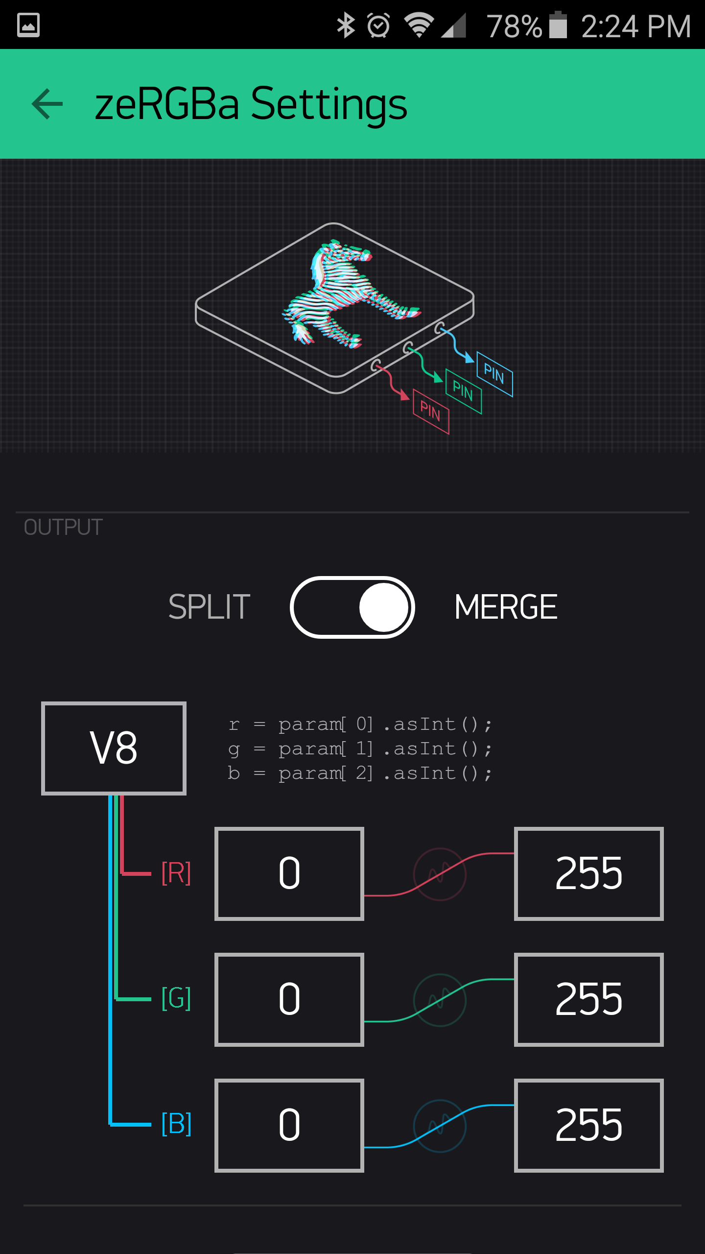
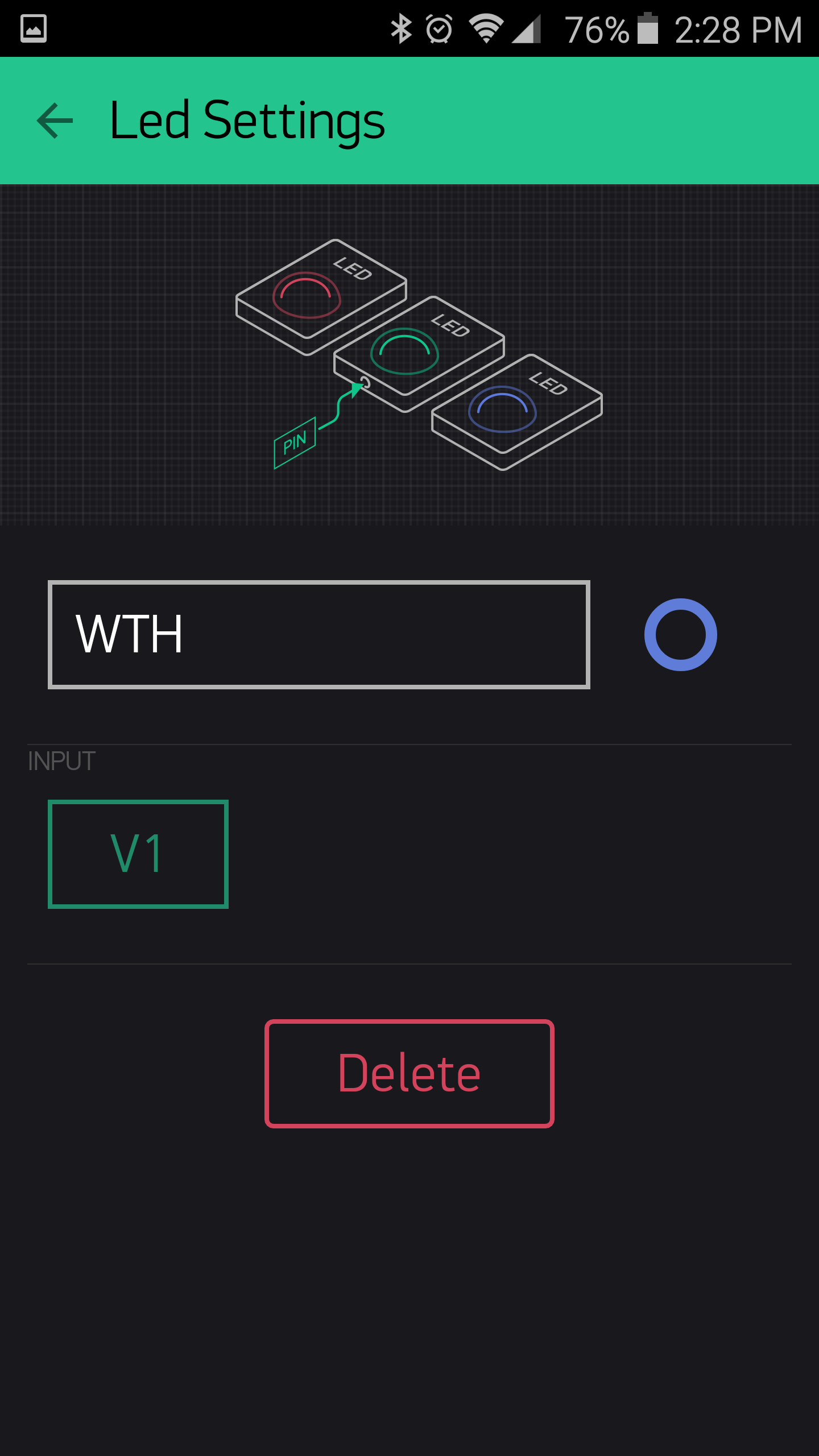
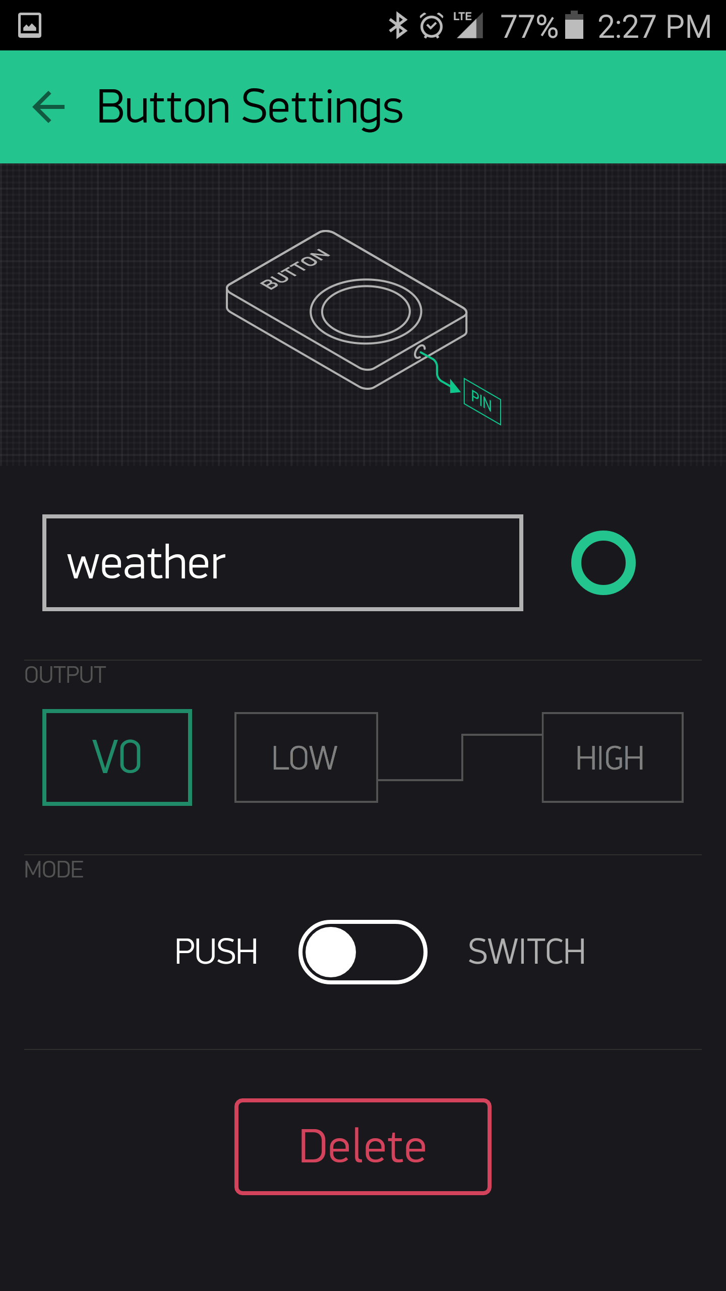
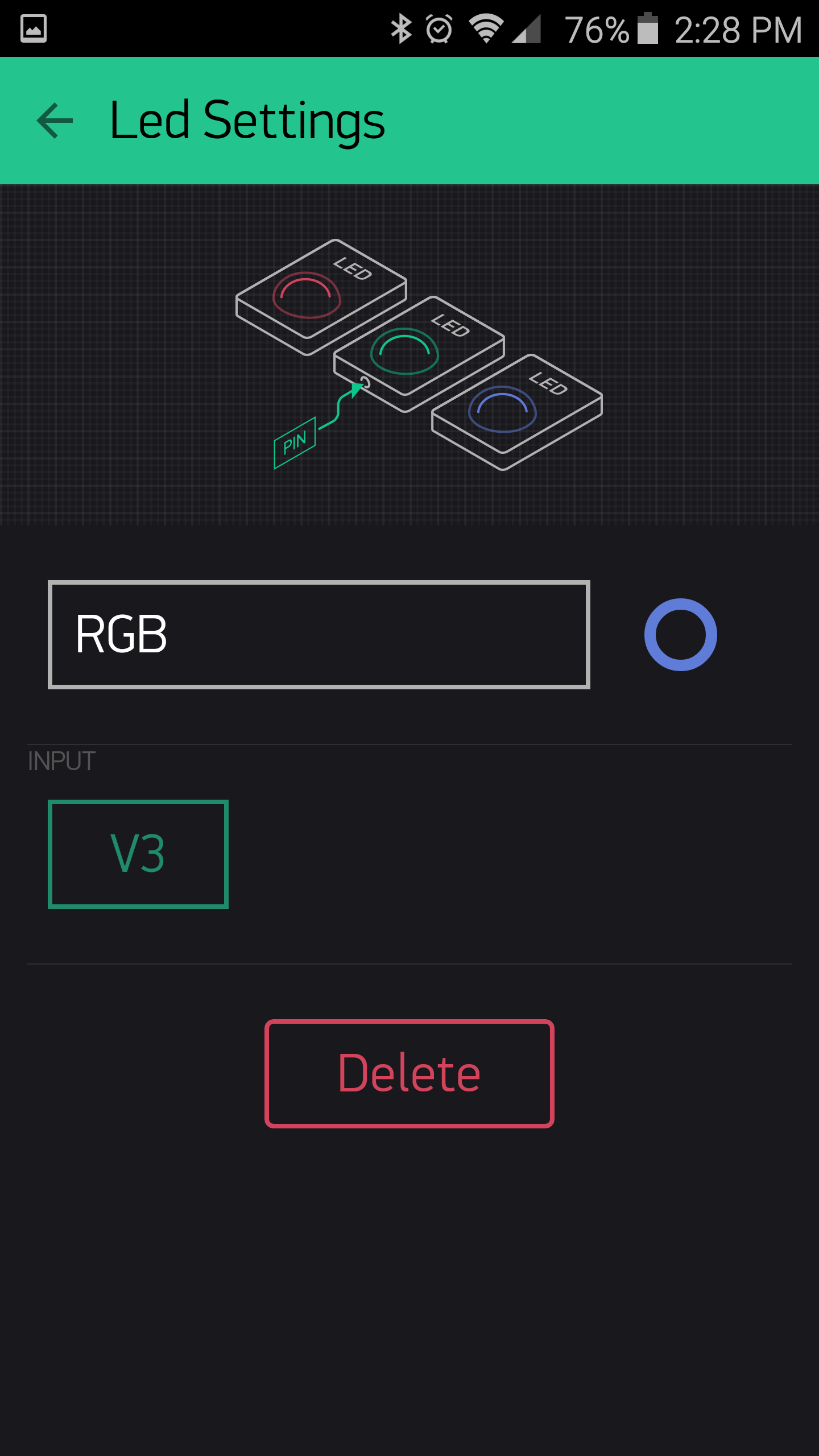
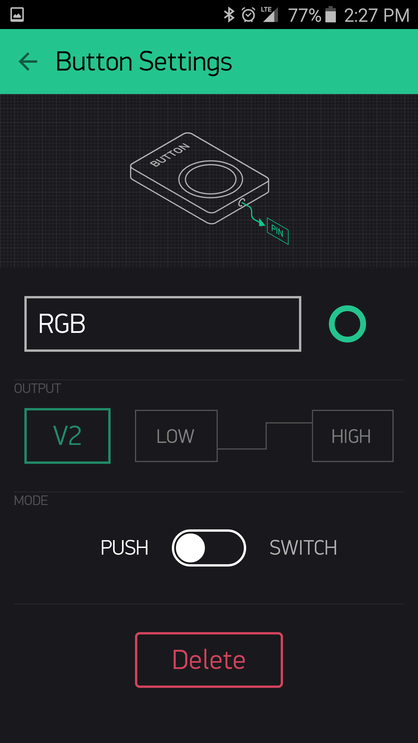
To get these things onto your project board, touch the screen and the left side should show things that you can place. Drag them over to wherever you'd like. Once they are placed on your board, you can click on them to assign them pins. All of ours are going to be assigned to virtual pins in the table below. There is also a step by step photo setup to help you:
| Module | Pin | |||
|---|---|---|---|---|
| Weather Button | V0 | |||
| Weather Indicator LED | V1 | |||
| RGB Button | V2 | |||
| RGB Indicator LED | V3 | |||
| Disco Button | V4 | |||
| Disco Indicator LED | V5 | |||
| ZERGBRA | V8 | |||
| LCD Screen | V9 | |||
Blynk app Photo Setup Walkthrough:

(remember to email yourself the Auth Tolken or you can come back to this page after you to get it.)
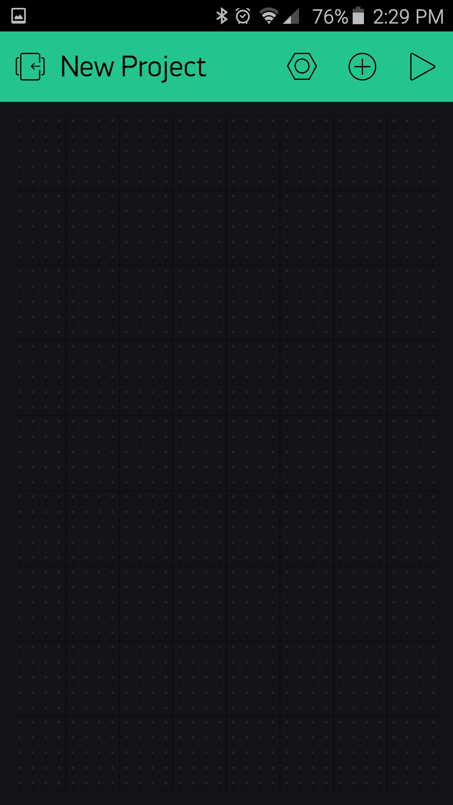
Swipe to the left to get the widget box menu, to pick new modules:
Once you have selected a module, it will appear on your project board. To attach it to a pin and change its setting, click on it:
Repeat those steps for all the modules attached to the pins you will need (as seen below):
After you have created all the LEDs, Buttons, the ZERGBA, and the LCD and assigned them to the correct virtual pins, you can arrange your modules to look like this:
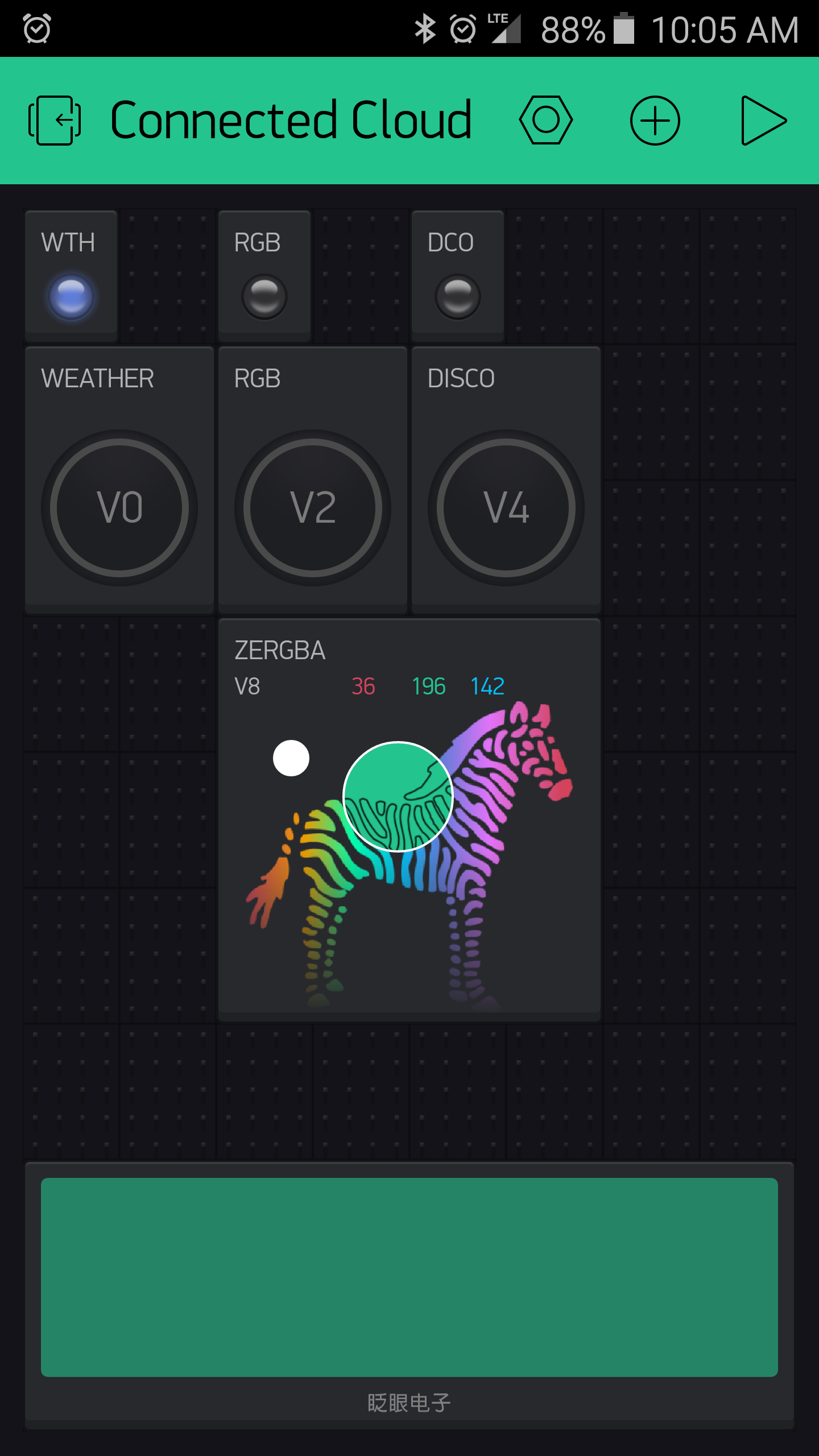
And now your blynk project is ready!
SparkFun Thing Code:
To program the SparkFun ESP8266 Thing, we have to get a little more complex.
To program this board, you will need a special add on for the Arduino IDE to be able to choose the ESP8266 board, and you can get the instructions for that in this tutorial.
You will also need to download the github libraries for Blynk, Adafruit’s Neo-Pixel Libraries, and lastly add the github libraries for this project.
Once you have done all of that, you can open the Thing code in the cloudcloud project, the sketch titled CloudCloud.ino, change the wifi and password to your network, add your Auth token from the Blynk app, and upload it to your SparkFun Thing to your computer. If you want weather for a city other than Niwot (which you probably do), you can change that in the code as well.
When uploading the code, remember to choose “SparkFun ESP8266 Thing” as your board under the Tools tab. Also check that you have the “Upload using: serial”, “CPU frequency: 80 MHz”, and “Upload speed: 115200” chosen under the Tools tab as well. Make sure you Thing board switch is ‘ON’. Then choose the COM port that your Thing board is hooked up to, and press the Upload button.
(*If you are having errors when you try to upload of undefined libraries, make sure that you have added the file states.h to your project. If after that you are still having issues, it might be the version of the Arduino IDE that you are running, we wrote this on version 1.6.5 and recommend running it on that version.)
Once that is finished uploading, unplug the Thing board from your computer, hook it back up to the circuit, power your Pro Mini (that is also powering the Thing board), and your LED strip. Make sure your Thing board switch is turned on, and wait 30-60 secs. Open up your Blynk app, and run the project you created by pressing play in the top right corner. You should be all hooked up and able to control your lights from the app.
Phew, that was a lot of stuff, but we got through it! Now you can power your lights and your Pro Mini (that is also powering the Thing board) and power up your Blynk app and control your clouds!
Installing the Lights in the Clouds
Now that we have the lights up and running, we can place them into the cloud and test out how it looks.
Evenly distribute the lights between all the paper lanterns and look at the light distribution, and adjust accordingly.


After I felt good about the distribution, I tied the LED strip to the top of each paper lantern. Note that the LED strip isn’t very secured in the lantern. The reason for this is that I didn’t see a difference if I secured them or not. Since they will always be hanging in the same way, they aren’t going to shift very much, so just securing a part to the lantern seemed sufficient to me.

After the LED strip was in the cloud, I looked around and filled any bald spots on the lantern with more polyfil that I could now see due to the lights. I also covered any exposed LED strip with polyfil that I rolled to be more dense.


You can glue the polyfil on while the Cloud is lit to get a better idea of what it looks like.
After you have filled in all the uneven spots of the cloud with polyfil, you can install your cloud where you like and enjoy it’s colorful awesomeness!
ReplaceMeOpen
ReplaceMeClose
Resources and Going Further
Thanks for reading! Here are the links to all the resources used in this tutorial.
GitHub Files
Interested in some more crafty electronics projects? Take a look at some of our other tutorials: