How to Build a Remote Kill Switch
 Nate
Nate 
When Things Get Out of Control
I highly recommend building something that scares you every once and awhile. In this case, I’m planning to enter an autonomous vehicle into the AVC in 2016, and it's pushing my limits of comfort. A 1,000W motor with a large battery pack behind it mean that if things go wrong, it could be dangerous. For that reason, one of the new safety requirements of the AVC is a remote kill switch that allows the user to remotely power down the vehicle. This tutorial is my solution to safely disconnecting the motor from the motor controller in case things get out of control...
ReplaceMeOpen
ReplaceMeClose
Here's a quick video showing the kill switch controlling the 1kW motor (that just happens to be attached to a blender).
System Requirements
Here are the design requirements for my system. These should fulfill the kill switch safety requirements of the A+PRS rules.
- If user presses the green button the system should energize the cut-off relay allowing power to flow to the motor.
- If user presses the red button the system should de-energize the cut-off relay shorting the + and - of the motor causing the motor to brake.
- If user presses the yellow button the system should assert a signal pin. This will be connected to the master controller to let it know that the race is in “yellow flag” mode.
- If the vehicle fails to hear from the remote after a certain length of time the vehicle should go into safety-shutdown (de-energize the cut-off relay causing engine to brake).
- If the remote fails to hear a response from the vehicle (out of range), then go into disconnect mode (blink all three LEDs).
- If the link is re-established, then start in safety-shutdown mode.
I broke the killswitch system into two parts: the Vehicle Control Unit that lives on the vehicle and the Remote Control Unit that the human holds in their hand.
VCU Parts List
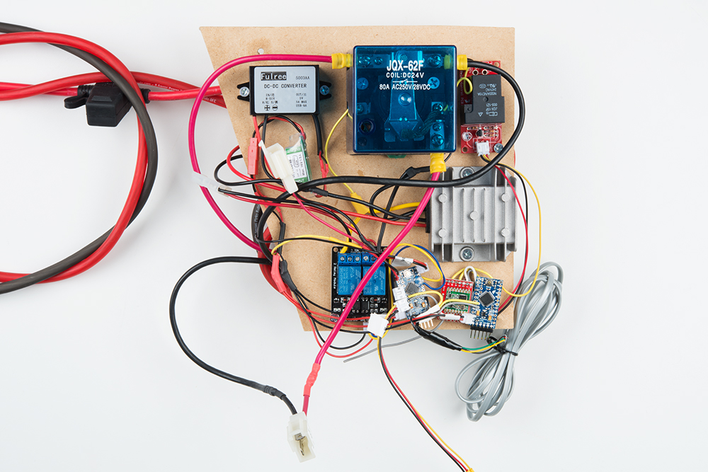
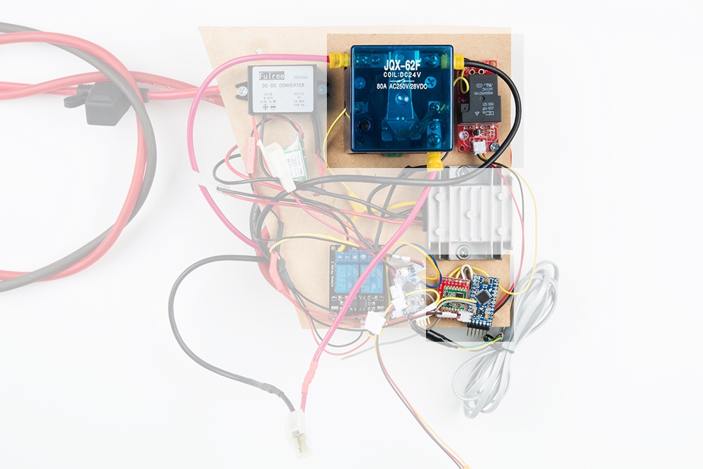
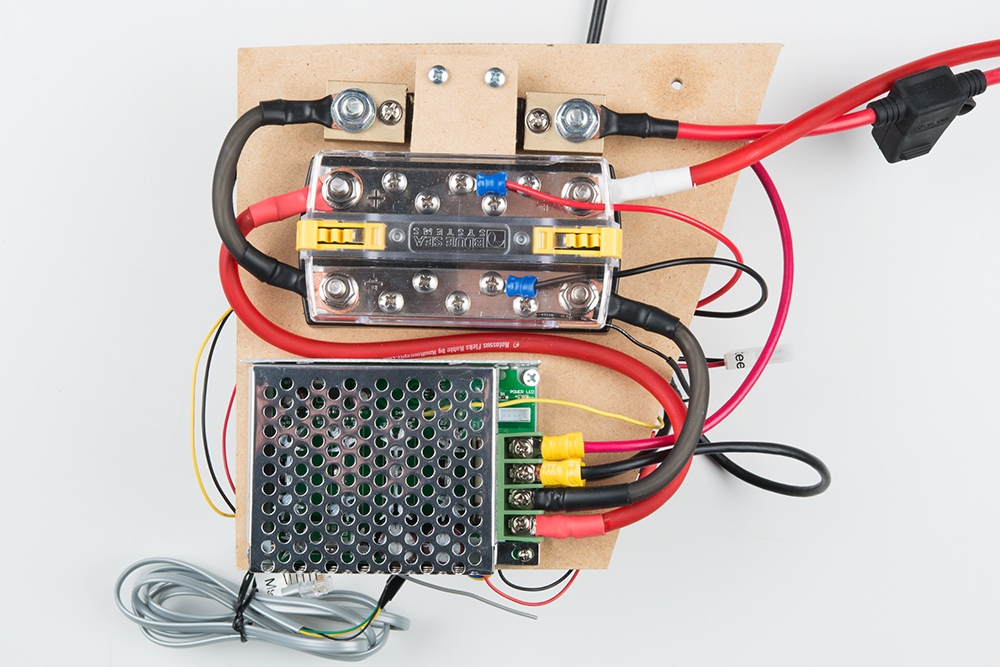
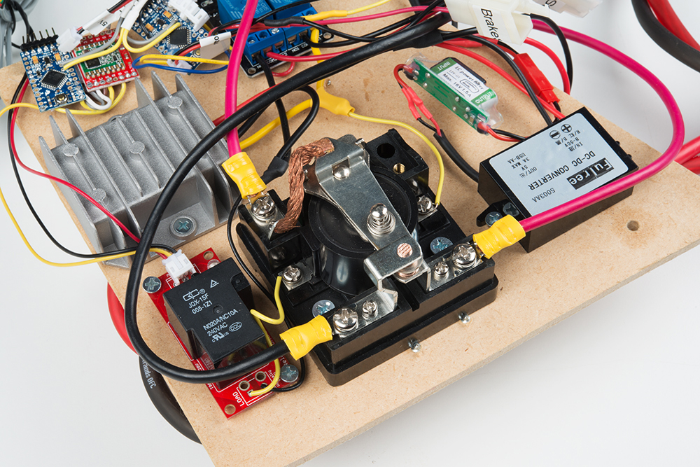
The Beefcake Relay can be seen next to the larger, blue, 24V/80A relay. The VCU itself (the Pro Mini connected to the RFM69 breakout board) can be seen in the lower right corner.
Parts used on the Vehicle Control Unit:
- Arduino Pro Mini 328 - 3.3V/8MHz
- RFM69 Breakout
- Beefcake Relay Control Kit
- 24VDC 80A Relay
- 48V to 24V DC to DC Buck Converter
- 48V to 5V DC to DC Buck Converter
- A handful of 3-Pin and 2-pin JST Jumper Wire Assemblies
I use our SparkFun RFM69 Breakout for a variety of reasons:
- Encryption: This allows me to rest easy that no one else (ok I’m sure someone could hack it) will power up/down my car.
- Software Defined Radio: The AVC has nearly 100 teams, all with their own radios and telemetry systems. It’s excellent to be able to sit in the 434MHz or 915MHz spectrum rather than the very crowded 2.4GHz arena.
- Data Rate Scaling: The data rates can be reduced and frequency changed so that range can be increased quite significantly. UKHASnet has even setup a network of RFM69 based repeaters across Europe with transmission ranges pushing 65km (40miles)! I plan to be within sight of my autonomous power wheels at all times, but it’s good to know the 100mW transmission power of the RFM69 can do the job.
- Library Support: The community has been writing various libraries to support the RFM type modules for years now. The latest I use for this project is RadioHead by AirSpayce. It does everything I need with some decent documentation to boot.
Vehicle Control Unit
The Vehicle Control Unit (VCU) sits between the motor controller and the motor. The VCU only connects the motor to power if the Remote Control Unit (RCU) is powered up and transmitting the ‘User pressed the green button, go for it’ signal.
I’ve decided to run my PRS vehicle at 48V, which is the higher end of allowed system voltages. Luckily, there are some really nice DC to DC buck converters to get 48V down to 24V (to control the cut-off relay) and 5V (to power the 3.3V Pro Mini). See the parts list for links to the particular ones I used.
Under load and at top speed, the motor controller will be putting out 10's of amps at 48V. The VCU needs a substantial relay big enough to handle that load. Some of the lowest cost, highest current relays I could find were 24V relays. Because my 3.3V/8MHz Pro Mini can only turn on/off 3.3V, I decided to use a two relay setup.
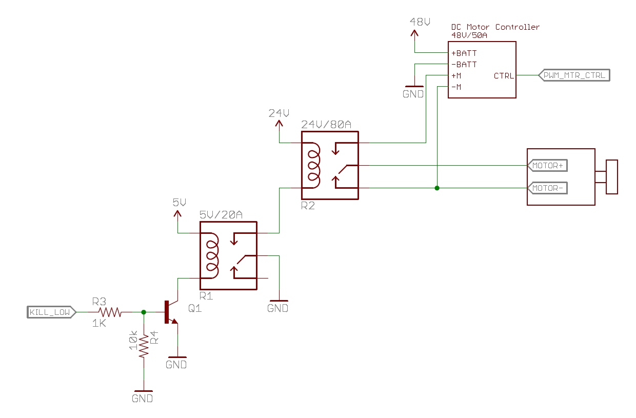
This is an example of a ‘bootstrapped’ relay system. Bootstrapping allows a small signal to control big loads. The 3.3V signal from the Pro Mini can’t control the large 24V relay directly, so I used the 3.3V signal to control a 5V relay to activate the 24V relay.
When we want to allow power to the motor, the Pro Mini activates the Beefcake Relay with a 3.3V signal (KILL_LOW goes from 0 to 3.3V). This signal grounds the Q1 transistor allowing current to flow across the coil in R1. Next, the reed on R1 moves from the normally closed position (where it is connected to nothing) to the normally open position. Current begins to flow freely from 24V through the R2 coil to ground. This flow causes the reed on R2 to move from the normally closed position to the upper position connecting the + lead of the motor to the +M on the motor controller. In real life, this whole process produces a most satisfying thunk. Note this does not power the motor; rather, it allows the motor controller to control the motor. If the motor controller is outputting 0% power, the motor will just sit happily still.
48V / 24V / 5V Subsystems
You may be wondering why I am running a 24V subsystem? For my A+PRS entry, I am controlling the steering with a 12V linear actuator that I am over-driving with 24V. The actuator is very strong but slow, and the extra voltage drives the actuator much faster. The 24V cut-off relay (R2) fit nicely into this design as well.
Motor Braking
When R2 is in the normally closed (unactivated) position, the + and - of the motor are shorted together. This is called motor braking. To see what this feels like, find a large DC motor, and try spinning the axle. It should be relatively easy. Now, short + and - of the motor together; the axle will be considerably harder to turn. By setting R2 up this way we have another layer of safety in that, if everything goes wrong and the Kill Switch goes haywire, the system should fail safe, turn off all the relays, short the motor and brake to a stop. It is not yet clear to me how aggressive this braking power is. If the braking is too abrupt (as in it ejects the human rider) it could be more dangerous than it is helpful, in which case I will disconnect the MOTOR- from the lower pin of R2 and let the motor freewheel in the event of a safety shutdown. That way the human passenger has the ability to control braking with the brake rather than something they cannot control.
RCU Parts List
Parts Used on the Remote:
- Three Button Switch Station Box
- Arduino Pro Mini 328 - 3.3V/8MHz
- RFM69 Breakout
- Red/Yellow/Green 5MM LEDs
- 850mAh LiPo Battery
- Lipo Charger Basic - Mini-USB
- Small Latching Power Switch or On/Off Slide Switch
- 4-Pin and 3-Pin JST Jumper Wire Assembly
- FTDI Basic Breakout - 3.3V for programming
- Right Angle Headers if you need them for your Pro Mini
Remote Control Unit
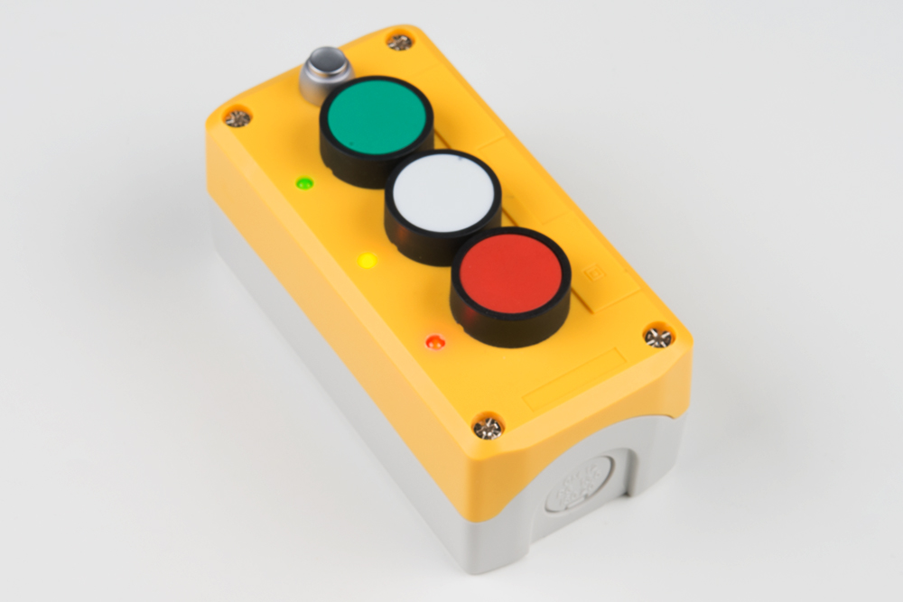
The RCU is the thing that the user holds in their hand and jams the red button in case the autonomous vehicle becomes sentient, or is just doing something it shouldn’t.
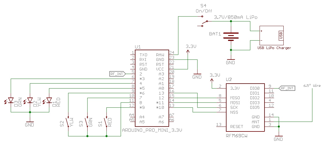
Let’s start with the simple bits: The LEDs are simply on/off and don’t need PWM pins. I chose to connect the LEDs to pins 3, 4, and 5 because it allowed me to solder in a 3-pin JST connector. The three buttons within the switch station are the Normally Open (NO) type. I wired them to pins 6, 7 and 9 with 8 serving as the ground pin. I did this because I ran out of GND pins on the Pro Mini. You can use a GPIO as ground, you just set it as an output and LOW. Also, by creating a bank of four pins it allowed me to solder a 4-pin JST directly to the Pro Mini.
The RFM69 is wired according to Mike’s excellent hookup guide. Note: The connection from pin 2 on the Pro Mini to DIO0 on the RFM69 is required and serves as the interrupt from RFM to Pro Mini. You cannot use a different pin on the Pro Mini because pin 2 is a hardware interrupt pin, and the library depends on interrupts.
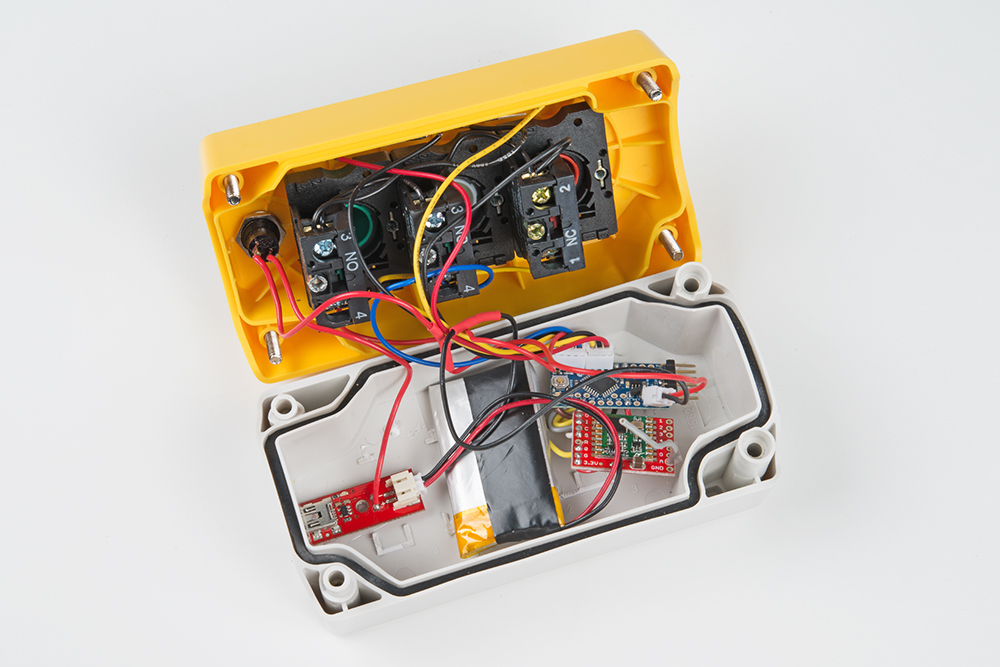
The remote needs to have a battery! I used the 3.7V 850mA LiPo. The average current draw is about 42mA, so this should last for around 20 hours on a charge. I didn’t do any power minimization efforts because 20 hours was plenty for my purposes. To avoid having to open and close the enclosure to charge the battery, I installed a LiPo charger with miniB connector. Plugging a miniB cable in will charge the battery any time, and pressing S4 (a latching switch) will turn on/off the remote. Note that if the remote is turned off, the vehicle will go into automatic safety shutdown (a good thing).
I really enjoy the quality and feel of the three buttons in the Switch Station, but they are very big and packing all the electronics into the enclosure is a challenge. If I were to build another remote, I would look for a better trade off of more room vs quality (there are many low quality switch stations on Amazon with more room inside the enclosure).
Code
Note: This example assumes you are using the latest version of the Arduino IDE on your desktop. If this is your first time using Arduino, please review our tutorial on installing the Arduino IDE.
If you have not previously installed an Arduino library, please check out our installation guide.You can find the latest code for the RCU and VCU in this github repo.
language:c
/*
 Remote Kill Switch - On the Car
 By: Nathan Seidle
 SparkFun Electronics
 Date: March 23rd, 2016
 License: This code is public domain but you buy me a beer if you use this and we meet someday (Beerware license).

 This is the part of the remote kill switch that lives on the car.

 If we receive 'R' (kill) system turns off the relay.
 If we receive 'Y' (pause) from the remote then set pin PAUSE high to signal master
 computer to pause.
 If we receive 'G' (go) system turns on relay, sets PAUSE pin to low.
 If we don't receive a system status from the remote every MAX_TIME_WITHOUT_OK ms, system goes into safety shutdown (relay off).

 Locomotion controller requires a 5V FTDI. The kill switch requires a 3.3V FTDI.
*/

#include <SPI.h>
#include <RH_RF69.h> //From http://www.airspayce.com/mikem/arduino/RadioHead/
#include <SimpleTimer.h> //https://github.com/jfturcot/SimpleTimer
#include <avr/wdt.h> //We need watch dog for this program

//If we don't get ok after this number of milliseconds then go into safety-shutdown
//This must be longer than MAX_DELIVERY_FAILURES * CHECKIN_PERIOD
//250ms is good
//L defines the value as a long. Needed for millisecond times larger than int (+32,767) but doesn't hurt to have.
#define MAX_TIME_WITHOUT_OK 250L

unsigned long lastCheckin = 0;

RH_RF69 rf69;

#define RELAY_CONTROL 9
#define PAUSE_PIN 6

#define LED_RED 5
#define LED_YLW 4
#define LED_GRN 3

//Define the various system states
#define RED 'R'
#define YELLOW 'Y'
#define GREEN 'G'
#define DISCONNECTED 'D'

char systemState;

void setup()
{
  wdt_reset(); //Pet the dog
  wdt_disable(); //We don't want the watchdog during init

  Serial.begin(9600);

  pinMode(RELAY_CONTROL, OUTPUT);
  turnOffRelay(); //During power up turn off power

  pinMode(LED_RED, OUTPUT);
  pinMode(LED_YLW, OUTPUT);
  pinMode(LED_GRN, OUTPUT);

  pinMode(PAUSE_PIN, OUTPUT);
  digitalWrite(PAUSE_PIN, LOW); //Resume

  if (!rf69.init())
    Serial.println("init failed");
  // Defaults after init are 434.0MHz, modulation GFSK_Rb250Fd250, +13dbM
  if (!rf69.setFrequency(915.0))
    Serial.println("setFrequency failed");

  // If you are using a high power RF69, you *must* set a Tx power in the range 14 to 20 like this:
  rf69.setTxPower(20);

  //This key is the same on the remote. Pick your own random sequence.
  uint8_t key[] = { 0xAB, 0x1C, 0x0E, 0x39, 0xF8, 0xFF, 0xA6, 0xFC,
                    0x7B, 0x44, 0xC3, 0xC0, 0x2D, 0x2D, 0x2D, 0xD2
                  };
  rf69.setEncryptionKey(key);

  systemState = RED; //On power up start in red state
  setLED(LED_RED);

  Serial.println("Power Wheels Kill Switch Online");

  wdt_reset(); //Pet the dog
//  wdt_enable(WDTO_1S); //Unleash the beast
}

void loop()
{
  if (millis() - lastCheckin > MAX_TIME_WITHOUT_OK)
  {
    if (systemState != DISCONNECTED)
    {
      setLED(LED_RED); //Turn on LED
      turnOffRelay();
      systemState = DISCONNECTED;

      Serial.println("Remote failed to check in! Turn off relay!");
    }
  }

  if (rf69.available())
  {
    uint8_t buf[RH_RF69_MAX_MESSAGE_LEN];
    uint8_t len = sizeof(buf);

    if (rf69.recv(buf, &len))
    {
      sendResponse(); //Respond back to the remote that we heard it loud and clear

      Serial.print("Received: ");
      Serial.println((char*)buf);

      if (buf[0] == RED || buf[0] == YELLOW || buf[0] == GREEN || buf[0] == DISCONNECTED) lastCheckin = millis(); //Reset timeout

      if (buf[0] == RED)
      {
        if (systemState != RED)
        {
          setLED(LED_RED); //Turn on LED
          turnOffRelay();
          systemState = RED;

          Serial.println("Kill!");
        }
      }
      else if (buf[0] == YELLOW)
      {
        if (systemState != YELLOW)
        {
          setLED(LED_YLW); //Turn on LED
          digitalWrite(PAUSE_PIN, HIGH);
          systemState = YELLOW;

          Serial.println("Pause!");
        }
      }
      else if (buf[0] == GREEN)
      {
        if (systemState != GREEN)
        {
          digitalWrite(PAUSE_PIN, LOW); //Turn off pause
          setLED(LED_GRN); //Turn on LED
          turnOnRelay();
          systemState = GREEN;

          Serial.println("Go!");
        }
      }
      else if (buf[0] == DISCONNECTED)
      {
        //If we've received a 'D' from the remote it means
        //it is trying to get back in touch
        setLED(LED_RED); //Turn on LED
        turnOffRelay();
        systemState = DISCONNECTED; //Remote will move the state from disconnected

        Serial.println("Reconnecting!");
      }

      Serial.print("RSSI: ");
      Serial.println(rf69.lastRssi(), DEC);
    }
  }
}

//If we receive a system state we send a response
void sendResponse()
{
  uint8_t response[] = "O"; //Send OK
  rf69.send(response, sizeof(response));
  rf69.waitPacketSent(50); //Block for 50ms before moving on

  Serial.println("Sent a reply");
}

//Turns on a given LED
void setLED(byte LEDnumber)
{
  digitalWrite(LED_RED, LOW);
  digitalWrite(LED_YLW, LOW);
  digitalWrite(LED_GRN, LOW);

  digitalWrite(LEDnumber, HIGH);
}

//Turn on the relay
void turnOnRelay()
{
  digitalWrite(RELAY_CONTROL, HIGH);
}

//Turn off the relay
void turnOffRelay()
{
  digitalWrite(RELAY_CONTROL, LOW);
}
language:c
/*
 Remote Kill Switch - Hand Held Controller
 By: Nathan Seidle
 SparkFun Electronics
 Date: March 23rd, 2016
 License: This code is public domain but you buy me a beer if you use this and we meet someday (Beerware license).

 This is the part of the remote kill switch that the user holds in their hand.

 If red button pressed we send 'R' (kill). Turn on red LED.
 If yellow button pressed we send 'Y' (pause). Turn on yellow LED.
 If green button pressed we send 'G' (go). Turn on green LED.
 Send the system state every CHECKIN_PERIOD ms. Car turns off if nothing is received after MAX_TIME_WITHOUT_OK ms.

 Indicator LEDs: Green/Yellow/Red

 Measured current: 42mA roughly

*/

#include <SPI.h>
#include <RH_RF69.h> //From: http://www.airspayce.com/mikem/arduino/RadioHead/s
#include <SimpleTimer.h> //https://github.com/jfturcot/SimpleTimer
#include <avr/wdt.h> //We need watch dog for this program

RH_RF69 rf69;

SimpleTimer timer;
long secondTimerID;

#define BUTTON_RED 9
#define BUTTON_GND 8
#define BUTTON_GRN 7
#define BUTTON_YLW 6

#define LED_RED 5
#define LED_YLW 4
#define LED_GRN 3

//Define the various system states
#define RED 'R'
#define YELLOW 'Y'
#define GREEN 'G'
#define DISCONNECTED 'D'

//Number of milliseconds between broadcasting our system state to the vehicle
//L defines the value as a long. Needed for millisecond times larger than int (+32,767) but doesn't hurt to have.
//25ms is good.
#define CHECKIN_PERIOD 25L

//Number of milliseconds to block for sending packets and waiting for the radio to receive repsonse packets
//This should be not be longer than the CHECKIN_PERIOD
//10ms is good.
#define BLOCKING_WAIT_TIME 10L

//How many failed responses should be allowed from car until we go into disconnect mode
#define MAX_DELIVERY_FAILURES 3
byte failCount = 0;

char systemState;

unsigned long lastBlink = 0;
#define BLINK_RATE 500 //Amount of milliseconds for LEDs to toggle when disconnected

void setup()
{
  wdt_reset(); //Pet the dog
  wdt_disable(); //We don't want the watchdog during init

  Serial.begin(9600);

  pinMode(BUTTON_RED, INPUT_PULLUP);
  pinMode(BUTTON_YLW, INPUT_PULLUP);
  pinMode(BUTTON_GRN, INPUT_PULLUP);
  pinMode(BUTTON_GND, OUTPUT);
  pinMode(LED_RED, OUTPUT);
  pinMode(LED_YLW, OUTPUT);
  pinMode(LED_GRN, OUTPUT);

  digitalWrite(BUTTON_GND, LOW);

  secondTimerID = timer.setInterval(CHECKIN_PERIOD, checkIn); //Call checkIn every 500ms

  if (!rf69.init())
    Serial.println("init failed");
  // Defaults after init are 434.0MHz, modulation GFSK_Rb250Fd250, +13dbM
  // No encryption

  if (!rf69.setFrequency(915.0))
    Serial.println("setFrequency failed");

  // If you are using a high power RF69, you *must* set a Tx power in the range 14 to 20 like this:
  rf69.setTxPower(20);

  //This key is the same on the car. Pick your own random sequence.
  uint8_t key[] = { 0xAB, 0x1C, 0x0E, 0x39, 0xF8, 0xFF, 0xA6, 0xFC,
                    0x7B, 0x44, 0xC3, 0xC0, 0x2D, 0x2D, 0x2D, 0xD2
                  };
  rf69.setEncryptionKey(key);

  systemState = RED; //On power up start in red state
  setLED(LED_RED);

  Serial.println("Remote Controller Online");

  wdt_reset(); //Pet the dog
//  wdt_enable(WDTO_1S); //Unleash the beast
}

void loop()
{
  timer.run(); //Update any timers we are running
  wdt_reset(); //Pet the dog

  if (digitalRead(BUTTON_RED) == HIGH) //Top priority (Red is NC to ground so high = pressed)
  {
    systemState = RED;
    setLED(LED_RED); //Turn on LED

    //Check the special case of hitting all three buttons
    if (digitalRead(BUTTON_YLW) == LOW && digitalRead(BUTTON_GRN) == LOW) shutDown(); //Go into low power sleep mode
  }
  else if (digitalRead(BUTTON_YLW) == LOW)
  {
    systemState = YELLOW;
    setLED(LED_YLW); //Turn on LED
  }
  else if (digitalRead(BUTTON_GRN) == LOW)
  {
    systemState = GREEN;
    setLED(LED_GRN); //Turn on LED
  }
}

//Powers down all LEDs, radio, etc and sleeps until button interrupt
void shutDown()
{
  //Turn off LEDs
  digitalWrite(LED_RED, LOW);
  digitalWrite(LED_YLW, LOW);
  digitalWrite(LED_GRN, LOW);

  //Turn off radio

  //Sleep microcontroller and wake up on button interrupt

  Serial.println("Powering down");
}

//Send the system status notification every CHECKIN_PERIOD number of ms
void checkIn()
{
  wdt_reset(); //Pet the dog

  if(systemState == RED)
  {
    sendPacket("R");
  }
  else if (systemState == YELLOW)
  {
    sendPacket("Y");
  }
  else if (systemState == GREEN)
  {
    sendPacket("G");
  }
  else if (systemState == DISCONNECTED)
  {
    if(millis() - lastBlink > BLINK_RATE)
    {
      lastBlink = millis();
      digitalWrite(LED_RED, !digitalRead(LED_RED));
      digitalWrite(LED_YLW, !digitalRead(LED_YLW));
      digitalWrite(LED_GRN, !digitalRead(LED_GRN));

      sendPacket("D"); //Attempt to re-establish connection
    }
  }
}

//Sends a packet
//If we fail to send packet or fail to get a response, time out and go to DISCONNECTED system state
void sendPacket(char* thingToSend)
{
  Serial.print("Sending: ");
  Serial.println(thingToSend);

  rf69.send((uint8_t*)thingToSend, sizeof(thingToSend));

  rf69.waitPacketSent(BLOCKING_WAIT_TIME); //Wait for a bit of time

  //Wait for a "O" response from the car
  boolean responseFromCar = rf69.waitAvailableTimeout(BLOCKING_WAIT_TIME); //Wait some ms time to get a response

  //Read in any response from car
  uint8_t buf[RH_RF69_MAX_MESSAGE_LEN];
  uint8_t len = sizeof(buf);
  if (rf69.recv(buf, &len))
  {
    Serial.print("Heard from car: ");
    Serial.println((char*)buf);
  }

  if(responseFromCar == true) //We got a response
  {
    failCount = 0; //Reset the count

    if(systemState != DISCONNECTED)
    {
      Serial.println("System status delivered");
    }
    else if(systemState == DISCONNECTED)
    {
      //We are back online!
      Serial.println("Back online!");
      setLED(LED_RED);
      systemState = RED; //Default to stop if we are regaining connection
    }
  }
  else if (responseFromCar == false)
  {
    Serial.println("No response from car");

    //Go into triple blink mode indicating disconnect
    if(systemState != DISCONNECTED)
    {
      if(failCount++ > MAX_DELIVERY_FAILURES)
      {
        failCount = MAX_DELIVERY_FAILURES; //Don't let it increase and roll over
        digitalWrite(LED_RED, HIGH);
        digitalWrite(LED_YLW, HIGH);
        digitalWrite(LED_GRN, HIGH);
        systemState = DISCONNECTED;
      }
    }

    rf69.setModeIdle(); //This clears the buffer so that rf69.send() does not lock up
  }
}

//Turns on a given LED
void setLED(byte LEDnumber)
{
  digitalWrite(LED_RED, LOW);
  digitalWrite(LED_YLW, LOW);
  digitalWrite(LED_GRN, LOW);

  digitalWrite(LEDnumber, HIGH);
}
The RCU waits for the user to press a button and monitors the link to the VCU. If the link is not detected, the RCU flashes all three LEDs letting the user know the VCU is offline (either unpowered or out of range). Once the user presses the green button, the RCU turns the LED to green and begins transmitting the ‘Ok, go for it’ signal. Once received, the VCU sets the KILL_LOW pin to high, thus activating both relays and connecting the motor to the motor controller.
Certain settings can be changed in the code for your specific application:
- MAX_DELIVERY_FAILURES: It turns out that the RF link will drop a packet every once and a awhile, so the MAX_DELIVERY_FAILURES is set to three. If we don’t get a valid send/response after 3 tries, the system goes into disconnected mode. Setting this lower than 3 means the car may shutdown prematurely because we had some RF traffic/collisions.
- CHECKIN_PERIOD: The remote will broadcast the system state every 25ms.
- MAX_TIME_WITHOUT_OK: The vehicle will shut down if it doesn’t hear from the remote after 250ms.
These settings worked well for me and created a responsive, dependable link that shut the vehicle down within 250ms if things went pear-shaped. You may need to adjust these settings for other, longer-range applications.
Future Improvements - Reverse!
The kill switch is working nicely over a long range and I have moved on to other challenges on the vehicle. Testing will tell if motor braking is a good thing or not. I’m also pretty sure Mr. Auto is going to drive me into the barrier quite often during testing and I’ll need the ability to stop and back up. As designed, the system doesn’t have the ability to reverse. For that I’ve looked into continuous duty solenoids. These are common on golf carts and other small DC vehicles. I’m waiting to find a cheap, used one somewhere to keep from going over the $500 PRS budget.
I hope you can learn a bit from my setup. If you have similar projects please link them in the comments. One of the great aspects of the AVC is all the great stuff I learn from other people so please let me know how you did your kill switch!