RFM69HCW Hookup Guide
 MikeGrusin
 Introducing the RFM69
The RFM69HCW is an inexpensive and versatile radio module. You can use it to send text or binary data between two or hundreds of modules. It's perfect for building inexpensive short-range wireless networks for home automation, citizen science, and more. The RFM69HCW comes in two frequency flavors; a 915 MHz version and a 434 MHz version. See the Hardware Overview below for tips on which one to choose.
Interface and Example Code
The RFM69HCW can't do anything by itself; it needs to be connected to a microcontroller such as an Arduino. The RFM69HCW uses a four-wire Synchronous Peripheral Interface (SPI) plus an interrupt line. Most microcontrollers, including the Arduino, offer an SPI interface.
Felix Rusu of LowPowerLab has written an excellent Arduino library for the RFM69 that handles the details of setting up the module and sending and receiving data. This guide will cover interfacing the RFM69HCW to an Arduino microcontroller using this library.
If you're using a different microcontroller, the information here plus the datasheet and the library source code should help get you up and running. (If you write example code for another system, we'll be glad to add it to the code repository).
Required Materials
In this tutorial we'll show you how to get two modules talking to each other, but keep in mind that you can use more than two modules in your projects.
Here's what you'll need:
Two RFM69HCW modules (with matching frequencies):
You'll need two Arduinos. You can use the RFM69HCW with any Arduino, but the 3.3V Arduino Pro is a good choice because the RFM69HCW is also a 3.3V part. We're using the "Beefy 3" FTDI board, because the standard FTDI board can't supply enough current to run the RFM69:
- 2 x Arduino Pro 328 3.3V
- 2 x Female Header Pack
- 2 x "Beefy 3" FTDI board
- 2 x USB Micro-B Cable
We'll connect these to the Arduinos using headers and jumper wires:
If you'd rather use 5V Arduinos you can, but you will need a Logic Level Converter for each 5V Arduino:
You'll need some wire to make antennas, and a couple of LEDs (optional) that we'll make blink when data is sent or received:
- About 1 foot of general-purpose wire (e.g. AWG22 Hook-Up Wire), or you can use a jumper wire in a pinch.
- 2 x general-purpose LEDs (e.g. Basic Red LED)
If you don't already have them, you will also need soldering tools and solder.
Suggested Reading
We recommend you be familiar with the following topics before working with the RFM69HCW. If you'd like to brush up on any of these things, follow the links and come back when you're done.
How to Solder: Through-Hole Soldering
Using GitHub
Installing an Arduino Library
Serial Peripheral Interface (SPI)
What is an Arduino?
Installing Arduino IDE
How to Solder: Castellated Mounting Holes
Hardware Overview
Frequency
The RFM69HCW transmits in the ISM (Industry Scientific and Medical) band, a set of frequencies set aside for low-power, short-range, license-free radios.
SparkFun sells two versions of the RFM69HCW, a 915 MHz version and a 434 MHz version. These frequencies are legal in different areas: very roughly, 915 MHz is for use in the Americas and Australia, and the 434 MHz version is for use in Europe, Asia and Africa. The actual regulations are a bit of a patchwork, so check your local regulations for other areas.
Range
How far will the signal reach? Outside with few obstructions, you should be able to get a solid link for hundreds of meters. Indoors we've seen it work for over 50 meters through multiple walls.
The RFM69HCW is capable of transmitting at up to 100 mW and up to 300 kb/s, but you can change both of those values to fit your application. For example, you can maximize range by increasing the transmit power and reducing the data rate. Or you can reduce both for short-range wireless sensor networks that sip battery power.
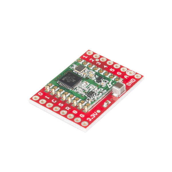
Board Pinout
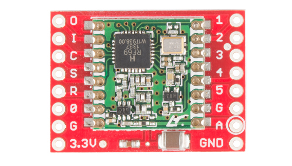
The RFM69HCW Breakout Board gives you access to all the pins on the RFM69HCW, but in the majority of cases you'll only need seven of them. Here's an overview of the pins we'll be using:
Power
| Board Label | Name | Function |
| 3.3V | Power | 3.3V power supply (at least 130 mA, see below) |
| G / GND | Ground | Power ground |
Data
| Board Label | Name | Function |
| O / MISO | Master In Slave Out | Data from RFM69HCW to microcontroller |
| I / MOSI | Master Out Slave In | Data from microcontroller to RFM69HCW |
| C / SCK | Serial ClocK | Clock signal from microcontroller to RFM69HCW |
| S / NSS | Slave Select | Select signal from microcontroller to RFM69HCW |
| 0 / DIO0 | Digital I/O 0 RX interrupt |
Received data ready interrupt signal from RFM69HCW to microcontroller |
Antenna
| Board Label | Name | Function |
| A / ANT | Antenna | Wire antenna, see the next page for details |
| G / GND | Ground | Antenna ground (same as power ground) (You can use either G pin adjacent to the antenna pin) |
The unused pins labeled 1 to 5 have functions that we won't be using. See the RFM69HCW datasheet for more information.
Power requirements
The RFM69HCW will run on voltages from 1.8V to 3.6V, and can draw up to 130mA of current when it's transmitting.
The easiest way to use this board is to connect it directly to a 3.3V Arduino such as the 3.3V Arduino Pro. However, you can connect it to a 5V Arduino if you use a logic-level translator. See the diagram in the Hardware Connections section.
In this tutorial we'll use two 3.3V Arduino Pros powered by the "Beefy 3" FTDI basics. We're using the Beefy 3 FTDI because it can provide up to 500mA, as opposed to the standard FTDI which can only provide 50mA.
Incidentally, the RFM69HCW uses 16mA when it's in receive mode, and it has several sleep options that use less than that.
Hardware Connections
Connecting the RFM69HCW to an Arduino
There are lots of ways to connect boards together. In this tutorial, we're going to solder Male Breakaway Headers to the RFM69HCW board, solder Female Headers to the Arduino Pro, and use M/F Jumper Wires to connect everything together. Of course, you can use whatever wiring methods you wish.
Step 1: Solder male header onto the RFM69HCW:
Break off one 8-pin length of Male Breakaway Header, and solder it to the "O I C S R 0 G 3.3V" side of the RFM69HCW board. You can solder it to the top or bottom, your choice.
Repeat for the second RFM69HCW.
Step 2: Solder female headers onto the Arduino Pro:
Solder the four Female Headers to the Arduino Pro. They should stick out of the top of the board.
Repeat for the second Arduino Pro.
Step 3: Use M/F jumper wires to connect the RFM69HCW to the Arduino Pro:
Different Arduino models use different pins for the SPI port. See the following table for the proper connections:
| RFM69HCW pin | 328 (Pro/Mini/Redboard/Uno) | Mega | 32U4 (Leonardo/Due/Pro Micro) |
| O / MISO | 12 or ICSP-1 | 50 or ICSP-1 | 14 or ICSP-1 |
| I / MOSI | 11 or ICSP-4 | 51 or ICSP-4 | 16 or ICSP-4 |
| C / SCK | 13 or ICSP-3 | 52 or ICSP-3 | 15 or ICSP-3 |
| S / NSS | 10 | 53 | 10 |
| 0 / DIO0 | 2 | 2 | 3 |
| 3.3V | 3.3V (labeled "VCC" on Pro/Mini) | ||
| G / GND | GND | ||
| A / ANT | See the next section for antenna information | ||
If you use the ICSP header for your SPI connection, note the pin numbering:
| 1 | 2 |
| 3 | 4 |
| 5 | 6 |
Wiring Diagrams
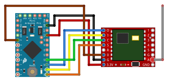
3.3V Arduinos
As we've mentioned, it's easiest to connect the RFM69HCW directly to a 3.3V Arduino such as the Arduino Pro:
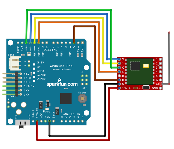
Be sure that you're powering your Arduino with a "Beefy 3" FTDI board, a wall-wart, or a Lipo battery. A normal FTDI Basic won't be able to supply enough current to run the RFM69HCW.
A 3.3V Arduino Pro Mini is also a great choice, since both boards are very small:
5V Arduinos
You can connect the RFM69HCW to a 5V Arduino, such as our RedBoard, if you use a logic level translator between them. The translator translates the Arduino's 5V signals to 3.3V signals, which won't damage the RFM69HCW:
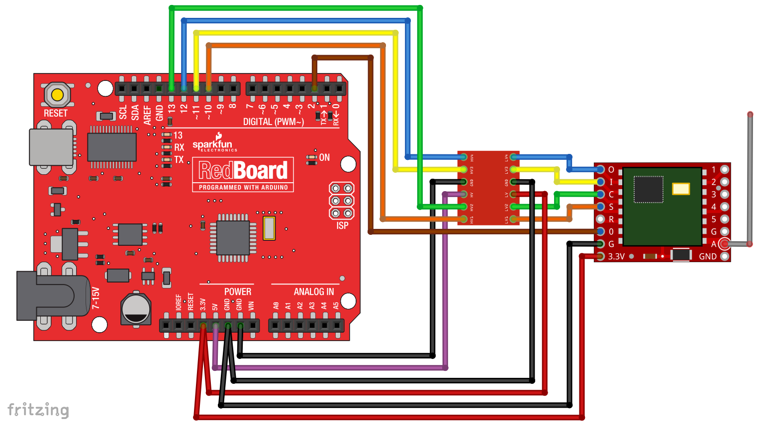
5V Arduinos have both a 5V and a 3.3V supply. Here we're using the 5V supply (purple wire) to power the high-voltage side of the logic level translator, and the 3.3V supply (red wire) to power both the RFM69HCW and the low-voltage side of the logic level translator. Remember to never connect 5V to the RFM69HCW.
External Status LED
One more thing: the example code we'll get to in a few pages blinks a LED to indicate when data is sent or received.
Unfortunately we can't use the Arduino's built-in LED for this, because that port (D13) is also used by the SPI port's SCK line. We use the SPI port to communicate with the RFM69HCW, so this LED will be on a lot of the time.
To make up for this, the example code is written so you can stick any old LED into your Arduino, with the long (positive) lead in D9, and the short (negative) lead in D8.
This step is optional, and not required for the normal operation of the RFM69HCW.
(Normally we would want to include a current-limiting resistor in series with the LED to prevent it from being burned out. But for simplicity, we'll rely on the current-limiting built into the Arduino's I/O ports, along with the fact that we'll only be turning it on for very brief periods to indicate packets sent or received.)
The Antenna
Creating an antenna is not as hard as it may sound. The simplest antenna is a wire cut to the proper length and soldered to the "A / ANT" pin. The length depends on the frequency of your board and is marked on the bottom of the board for your convenience:
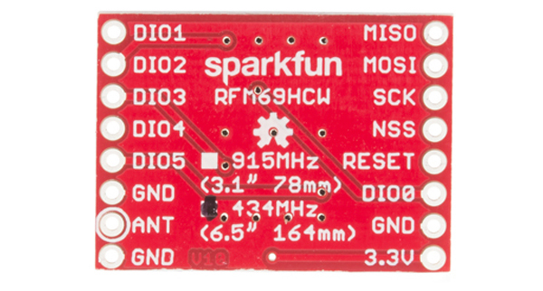
| Frequency | Length (inches) | Length (mm) |
| 915 MHz | 3.07" (3 + 1/16") | 78mm |
| 434 MHz | 6.47" (6 + 1/2") | 164mm |
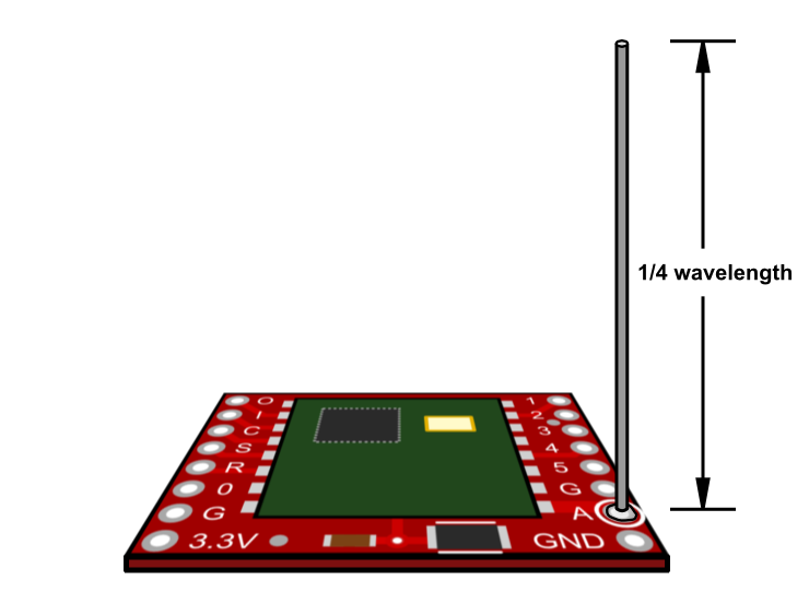
FYI: This is called a quarter-wave antenna because the length is one-quarter of a full wavelength at the transmission frequency.
Antenna Placement
For antenna placement you have a few options:
Single Antenna
The simplest option is to solder a properly-sized antenna wire to the "A" / "ANT" header hole (the one with the circle around it), and stick it straight up. That's it!
If you need the antenna to be shorter to fit within a plastic box, you can bend or coil the antenna (this will adversely affect the range and directionality), but don't change the length unless you know what you're doing.
If you're using a metal box, you should pass the antenna through a hole and extend it outside the box (see below). Also try to keep your radio module and antenna away from large metal objects, as the metal will disrupt the transmission.
You will get good results from this basic antenna, but if you want to maximize your range, consider the following options as well:
Add a Dipole
Antennas love to have a ground underneath them. The RFM69HCW board contains a ground, but, the larger the ground, the better. A dipole is an antenna that has an equal length of grounded wire extending below the board. This creates a virtual ground that will increase the gain of the antenna.
To make a dipole, cut a second wire the same length as your antenna, solder it to one of the "G" / "GND" header holes adjacent to the antenna, and point it in the opposite direction of the antenna (straight down instead of up).
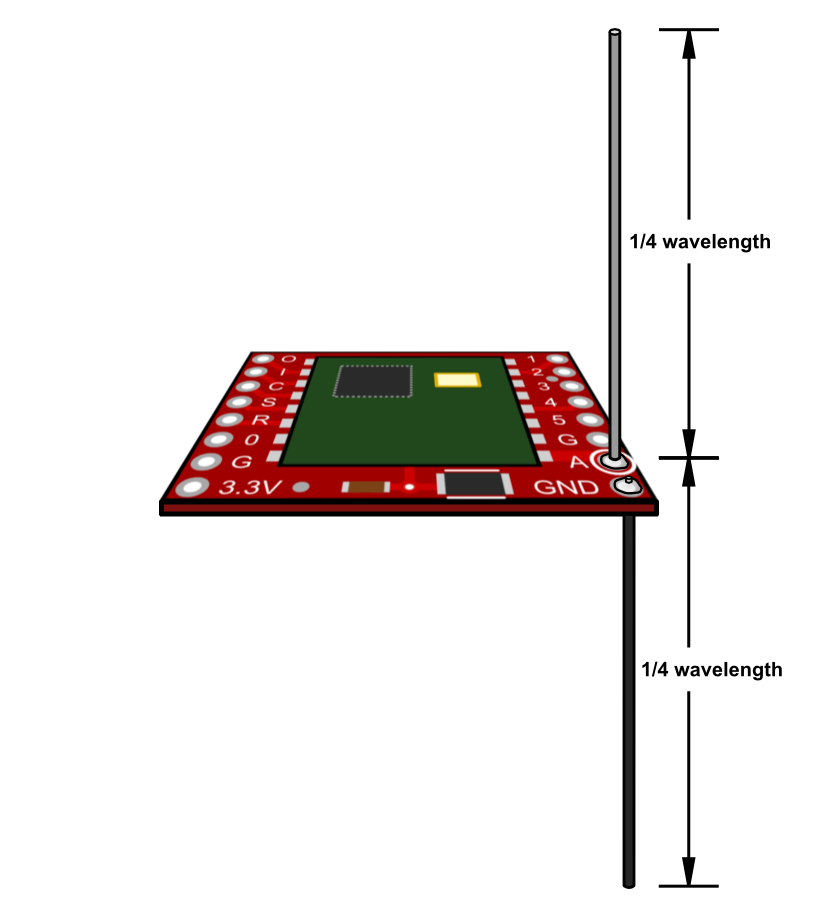
Keep both wires straight, in free air, and away from large metal objects if possible.
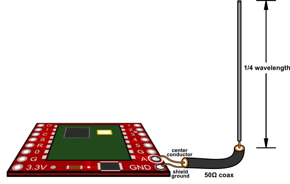
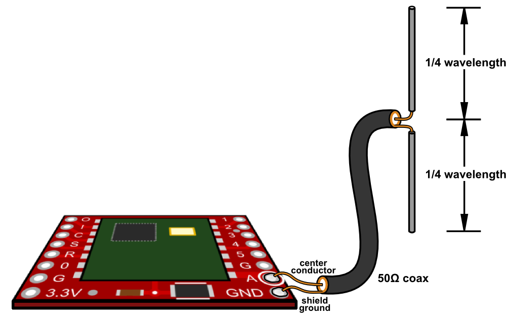
Remote Mounting
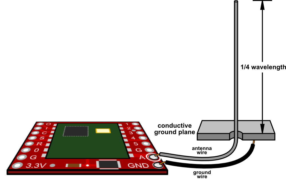
You can mount the antenna a short distance away from the board by (ideally) using 50-ohm coaxial cable, or (less ideally) by running a ground wire next to it. At the point where your antenna begins, simply end the coaxial shield / ground wire, or connect it to your ground plane (see below) or dipole. (The unshielded portion of your antenna should be 1/4-wave long as discussed above).
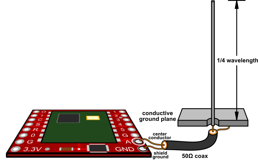
Using a Ground Plane
Because antennas love to have a ground underneath them, the best antennas stick up above a well-grounded surface. If you're using a metal box,or mounting the antenna on a vehicle roof, you can extend the antenna through and above the metal surface, as long as the surface is grounded. (Ensure that the antenna conductor doesn't short out against the ground plane where it passes through it.) If you don't have a handy metal surface you can create workable ground planes with a grid of copper tape or foil, radial grounded wires, etc.
Connecting a Commercial Antenna
If you'd like to connect a commercially-available antenna, you can solder an SMA Connector to the RFM69HCW board. Position the connector over the three headers marked G / A / G, and solder on both sides to ensure a good connection.
Other Antenna Types
The quarter-wave antenna is simple and effective, but, if you need additional range, there are other antenna designs like the Yagi that are far more directional, which is useful if you can point your antennas towards each other.
We're not antenna experts, so this is where we'll leave you. But if you're interested in this topic, consider getting involved in amateur radio. It's a great way to learn about antenna design and many other things: www.arrl.org.
How it Works
"How does... how does it work?"
"I know not, my Liege"
"Consult the Book of Armaments!"
-Monty Python and the Holy Grail
The information below will help you better understand how your RFM69HCW module works, which will help you use it more effectively in your projects. However, if you're itching to start using it right away, you can jump straight to Running the Example Code.
Packets
To save power and let multiple modules share the same frequency, the RFM69HCW doesn't transmit continuously. Instead, it sends short bursts of data called packets. You can think of these as short messages sent from one RFM69 to another.
Packets can be sent very quickly and repeatedly, giving the illusion of a continuous connection. And, because the transmitter is on only for the fraction of a second it takes to transmit each packet, many modules can share the same frequency.
Each packet can contain up to 61 bytes of data. This is the actual message that you're sending from one node to another. This data can be text characters or binary numbers; as far as the RFM69 is concerned, it's just a block of data. If you need to send more than 61 bytes, just send more packets.
The format of the message (what it contains) is entirely up to you. Normally you'll come up with a format for your specific application (e.g. "three decimal numbers separated by spaces"), and write your code so that both the sender and receiver expect the same format.
Addressing
In order for a message to get from one RFM69 to another, each module (often called a node) must be given its own address. Addresses consist of two numbers: the network number, which is like the town in which all the nodes live, and the node number which is like an individual street address. Each of these numbers can range from 0 to 255.
You get to (and must!) choose these numbers. Even if you just have two nodes, you'll need to give them address numbers in your code. The address is set by your code each time the RFM69HCW is powered up; it doesn't remember the address when it is powered off.
Network Number
The network number should be the same for all the RFM69HCWs that you want talking to each other. Each network will be isolated from all the others - modules in network 0 won't be affected by anything going on in network 1, etc. You can have up to 256 networks operating in the same area, numbered 0 to 255.
Node Number
The node number should be different for all your RFM69HCWs (on the same network). These are the individual addresses that are used to e.g. send a message from node 2 to node 3. You can have up to 255 nodes in a network, numbered 0 to 254.
Broadcast Address
Sharp-eyed readers may have noticed that node addresses only go to 254, not 255. That's because 255 is a special "broadcast" address; if you send a message to address 255, all of the nodes on that network will receive it.
"Promiscuous Mode"
Apart from the broadcast address, messages sent between nodes are usually "private." Nodes will normally ignore messages that aren't addressed to them.
However, you can turn on something called “promiscuous mode,” which tells the node to receive every message that it hears on the network. This can be useful for debugging, routing messages to and from the radio network, etc, but note that even promiscuous mode won’t let you hear messages sent on a different network.
Acknowledgement
When you send a message, you have the choice of sending it "in the blind," hoping that the receiver will pick it up, or you can request an acknowledgement (usually shortened to "ACK") that the message was received. In fact, the RFM69 library can automatically resend a message until it either receives an acknowledgement from the receiver (success!) or it has resent it a specific number of times without a response (fail).
Whether you use acknowledgements or not depends on your application. You may want to use acknowlegements if the data you're sending is very important or if you want to be sure that both ends of a link are functional. But, some applications work better in the blind, such as high-bandwidth data where a lost message isn't a big deal, beacons that multiple modules may receive, one-way links using highly-directional antennas, etc. It's up to you.
There's one catch: even though it's easy to request an acknowledgement when you send a message, the receiver will not automatically send an acknowlegement. Your code must check received messages for acknowledgement requests and send acknowledge messages manually. See the example code for details.
Encryption
As noted above, "promiscuous mode" will let you silently listen in on all the conversations going on in a given network. If you're sending sensitive information, this may not be good news to you since someone else may be listening to your conversations. Fortunately, the RFM69 can protect your communications using AES (Advanced Encryption Standard) encryption, which is extremely secure.
Encryption can be turned on or off by a library command (see the examples for details). You'll also need to make sure that both ends of your link are using the same 16-byte key. Only those RFM69s using exactly the same key will be able to decode the messages.
Running the Example Code
Felix Rusu of LowPowerLab has written an excellent Arduino library for the RFM69 that handles the details of setting up the module and sending and receiving data. This guide will cover interfacing the RFM69HCW to an Arduino microcontroller using this library.
If you're using a different microcontroller, the information here plus the datasheet and the RFM69 library source code should help get you up and running. (If you write example code for another system, we'll be glad to add it to our code repository).
Note that the author of the library keeps the most up-to-date version at github.com/LowPowerLab/RFM69. SparkFun has created their own repository for the RFM69HCW Breakout Board that includes a copy of this library plus hardware schematics, example code, etc. at github.com/sparkfun/RFM69HCW_Breakout.
Installing the RFM69 Library
Hopefully you've done a bit of Arduino programming and know how to install a library. If not, take a look at our tutorials on the process:
- Installing the Arduino IDE
- Using Github (to retrieve the example code and library)
- Installing an Arduino Library
NOTE: This library is not found in the Arduino Library Manger currently, so you'll have to download the library and add it using the Add .ZIP Library... option found under the Sketch > Include Library menu.
The basic process is:
Download a copy of the repository:
RFM69HCW GitHub Repository Open the above archive, go into the "Libraries/Arduino" folder, copy the "RFM69" folder, and add the folder via the Library Manager or paste it into your "Arduino/libraries" folder.
Restart your Arduino IDE.
Easy!
Plug in the Hardware
In this tutorial we're going to set up two Arduino / RFM69 nodes and get them to communicate with each other.
If you haven't yet, do the wiring steps on the Hardware Connections page of this tutorial.
At this point, you should have two matching Arduino plus RFM69HCW nodes. We'll need to figure out the serial ports associated with these nodes. Plug one USB cable into your computer. A new COM port number should be added to the Arduino IDE's "Tools/Port" list. Write it down. Now plug in the other USB cable from the second node. Another COM port number should appear. Write that one down as well.
Customize the Code for Each Node
Before you upload the code to your Arduino, you'll need to customize it for each node. Use the code below, and make the followinf changes for each separate node.
Node 1
Let's set it up for your FIRST node:
Near the top of the code, look for
#define NETWORKID, and change the value to 0. This will be the network all your nodes are part of, so it should be the same for all your nodes. (You can of course make this any number from 0 to 255, as long as it's the same for all your nodes.)Now look for the
#define MYNODEIDline, and change the value to 1. That will be this node's address.Look for the
#define TONODEIDline, and change the value to 2. That will be the other node's address; the one you'll be talking to.Below these lines will be a section for defining the radio frequency of your RFM69HCW board. Uncomment the line corresponding to your board's frequency, and make sure the others are commented (have // in front of them. If you forget it, the frequency is marked on the bottom of your RFM69HCW board).
If you want to use encryption, change the
#define ENCRYPTvalue totrue, and put a 16-character string of your choice into theENCRYPTKEYvalue. This key must be the same for all nodes on your network. Keep it a secret!Finally, if you wish to use acknowledgements, set
USEACKtotrue. If not, set it tofalse. Use the same setting for all your nodes.
// radio.setCS(10); //uncomment this if using Pro Micro
Now upload the sketch to your FIRST node. Remember that you should set the "Tools/Port" menu to the COM port you wrote down earlier for the FIRST node, and if you're using a 3.3V Arduino Pro as we recommend, you should set the "Tools/Board" menu to "Arduino Pro or Pro Mini" and "Tools/Processor" to "ATmega328 (3.3V, 8MHz)"
Node 2
Time to modify the sketch for the SECOND node.
Go back up to the
#define MYNODEIDline, and change the number to 2. That will be this node's address.Now look for the
#define TONODEIDline, and change the number to 1. That will be the other node's address; the one you'll be talking to.
See how we swapped the MYNODEID and TONODEID numbers? This way each node will send messages to the other one.
Upload the sketch to your SECOND node. Change the "Tools/Port" menu to the second COM Port you wrote down from above, and upload. That's it, we're done!
Load and Modify the Code
Copy the code from the below window into the Arduino IDE (be sure the editing window is completely blank first). After you've installed the RFM69 library, you can also find this code in the Arduino IDE under "File / Examples / RFM69 / SFE_RFM69HCW_example.ino". Don't forget to make the changes mentioned above.
language:c
// RFM69HCW Example Sketch
// Send serial input characters from one RFM69 node to another
// Based on RFM69 library sample code by Felix Rusu
// http://LowPowerLab.com/contact
// Modified for RFM69HCW by Mike Grusin, 4/16

// This sketch will show you the basics of using an
// RFM69HCW radio module. SparkFun's part numbers are:
// 915MHz: https://www.sparkfun.com/products/12775
// 434MHz: https://www.sparkfun.com/products/12823

// See the hook-up guide for wiring instructions:
// https://learn.sparkfun.com/tutorials/rfm69hcw-hookup-guide

// Uses the RFM69 library by Felix Rusu, LowPowerLab.com
// Original library: https://www.github.com/lowpowerlab/rfm69
// SparkFun repository: https://github.com/sparkfun/RFM69HCW_Breakout

// Include the RFM69 and SPI libraries:

#include <RFM69.h>
#include <SPI.h>

// Addresses for this node. CHANGE THESE FOR EACH NODE!

#define NETWORKID     0   // Must be the same for all nodes
#define MYNODEID      1   // My node ID
#define TONODEID      2   // Destination node ID

// RFM69 frequency, uncomment the frequency of your module:

//#define FREQUENCY   RF69_433MHZ
#define FREQUENCY     RF69_915MHZ

// AES encryption (or not):

#define ENCRYPT       true // Set to "true" to use encryption
#define ENCRYPTKEY    "TOPSECRETPASSWRD" // Use the same 16-byte key on all nodes

// Use ACKnowledge when sending messages (or not):

#define USEACK        true // Request ACKs or not

// Packet sent/received indicator LED (optional):

#define LED           9 // LED positive pin
#define GND           8 // LED ground pin

// Create a library object for our RFM69HCW module:

RFM69 radio;

void setup()
{
  // Open a serial port so we can send keystrokes to the module:

  Serial.begin(9600);
  Serial.print("Node ");
  Serial.print(MYNODEID,DEC);
  Serial.println(" ready");

  // Set up the indicator LED (optional):

  pinMode(LED,OUTPUT);
  digitalWrite(LED,LOW);
  pinMode(GND,OUTPUT);
  digitalWrite(GND,LOW);

  // Initialize the RFM69HCW:
  // radio.setCS(10);  //uncomment this if using Pro Micro
  radio.initialize(FREQUENCY, MYNODEID, NETWORKID);
  radio.setHighPower(); // Always use this for RFM69HCW

  // Turn on encryption if desired:

  if (ENCRYPT)
    radio.encrypt(ENCRYPTKEY);
}

void loop()
{
  // Set up a "buffer" for characters that we'll send:

  static char sendbuffer[62];
  static int sendlength = 0;

  // SENDING

  // In this section, we'll gather serial characters and
  // send them to the other node if we (1) get a carriage return,
  // or (2) the buffer is full (61 characters).

  // If there is any serial input, add it to the buffer:

  if (Serial.available() > 0)
  {
    char input = Serial.read();

    if (input != '\r') // not a carriage return
    {
      sendbuffer[sendlength] = input;
      sendlength++;
    }

    // If the input is a carriage return, or the buffer is full:

    if ((input == '\r') || (sendlength == 61)) // CR or buffer full
    {
      // Send the packet!


      Serial.print("sending to node ");
      Serial.print(TONODEID, DEC);
      Serial.print(", message [");
      for (byte i = 0; i < sendlength; i++)
        Serial.print(sendbuffer[i]);
      Serial.println("]");

      // There are two ways to send packets. If you want
      // acknowledgements, use sendWithRetry():

      if (USEACK)
      {
        if (radio.sendWithRetry(TONODEID, sendbuffer, sendlength))
          Serial.println("ACK received!");
        else
          Serial.println("no ACK received");
      }

      // If you don't need acknowledgements, just use send():

      else // don't use ACK
      {
        radio.send(TONODEID, sendbuffer, sendlength);
      }

      sendlength = 0; // reset the packet
      Blink(LED,10);
    }
  }

  // RECEIVING

  // In this section, we'll check with the RFM69HCW to see
  // if it has received any packets:

  if (radio.receiveDone()) // Got one!
  {
    // Print out the information:

    Serial.print("received from node ");
    Serial.print(radio.SENDERID, DEC);
    Serial.print(", message [");

    // The actual message is contained in the DATA array,
    // and is DATALEN bytes in size:

    for (byte i = 0; i < radio.DATALEN; i++)
      Serial.print((char)radio.DATA[i]);

    // RSSI is the "Receive Signal Strength Indicator",
    // smaller numbers mean higher power.

    Serial.print("], RSSI ");
    Serial.println(radio.RSSI);

    // Send an ACK if requested.
    // (You don't need this code if you're not using ACKs.)

    if (radio.ACKRequested())
    {
      radio.sendACK();
      Serial.println("ACK sent");
    }
    Blink(LED,10);
  }
}

void Blink(byte PIN, int DELAY_MS)
// Blink an LED for a given number of ms
{
  digitalWrite(PIN,HIGH);
  delay(DELAY_MS);
  digitalWrite(PIN,LOW);
}
Running the Sketches
You now have two nodes that will send messages to each other, but, to use them, we'll need to open two serial terminals.
One way to do this is to run two separate Arduino IDEs. You'll have to actually start Arduino twice - you can't just open a "new" code window from the first IDE.
Set one IDE to the COM port of the first node and the other to the COM port of the second. Then, open serial monitor windows from both IDEs.
In each serial monitor window, you'll need to set the baud rate to 9600 and make sure the "line ending" dropdown is set to "carriage return." (The example code uses carriage returns as a signal to send a packet.)
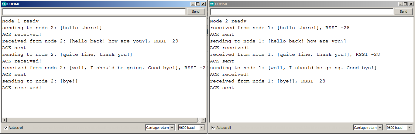
Once both windows are up, you should be able to type messages in the text entry box at the top of one window and press return to send the message to the other window. Try it!
You can also try turning ACKs and encryption on or off, using the "broadcast address" (255), etc.
You can also try this one of the many serial terminals mentioned in this tutorial.
Signal Strength
You might have noticed the "RSSI" number that the example code prints out. "RSSI" stands for "Receive Signal Strength Indicator;" it's a measurement of how strong the transmission was when a message was received.
This number is in decibels (dB), which means that when nodes are close to each other this will be a low number like -25, and, when they're further away, they'll be higher numbers like -50. Usually you'll ignore this number, but you could use it to estimate how far away nodes are from each other, provide a warning when the link is becoming weak, or, in sophisticated applications, vary the transmit strength so that you don't waste power unnecessarily.
Note: In this section and the example code, the notation of "number(s)" is in reference to the value's magnitude, as the signal strength is usually reported in values less than 0. To be technically accurate, the lower the value, the lower the power of the signal strength. (i.e. The value (-50)dB is less than (-25)dB; therefore, (-50)dB has a weaker signal strength and is probably further away.)
Resources and Going Further
For this tutorial, we connected both of the nodes to the same computer to make it easy to send messages from one node to another. But, remember that when you do your own projects, your nodes might be attached to weather stations, garage doors, Halloween decorations, drones, robots, your cat... the sky's the limit!
The example code has comments that explain how messages are sent and received. Feel free to use it as a basis for the code in your projects.
For advanced usage, you can also check out the other examples and source code in the library. The RFM69.h and RFM69.cpp files list all of the library functions and tell you a little bit about what they do.
For more information, check out the links below.
- RFM69HCW GitHub Repository
- RFM69HCW Schematic
- RFM69HCW Eagle Files
- RFM69HCW Datasheet
- SparkFun Product Showcase: Transceivers!
This transceiver is great for projects like building a remote kill switch to terminate power to your project when your robot goes... sentient.
How to Build a Remote Kill Switch
For more wireless fun, check out these other great SparkFun tutorials:
Wireless Controlled Wearable EL Wire Dance Suit
Wireless Remote Control with micro:bit
ESP32 Thing Plus Hookup Guide
Connecting Thing Plus Matter to Google Nest Hub
Are you looking to build a robot controlled by the RF69HCW? Try looking at these blog posts.