Single Supply Logic Level Converter Hookup Guide
 bboyho,
  LightningHawk
 Introduction
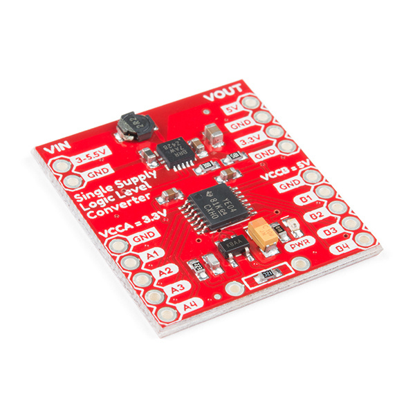
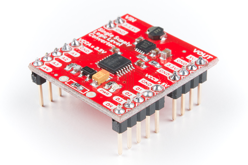
The Single Supply Logic Level Converter combines a boost converter (TPS61200), adjustable voltage regulator (MIC5205), and logic level translator (TXB0104) into one board. It provides 5V to the high side of the TXB0104 and the low side is programmable to 3.3V, 2.5V and 1.8V. The default low side voltage is 3.3V. With this device you can use your 5V microcontroller with 3.3V sensors and vice versa without the need for a second power supply!
What makes this logic level converter truly special is the fact that you can supply it with 3.3V and it will boost it to 5V - meaning you can use your 3.3V system, and convert directly to another 5V sensor - and even power your sensor or other board! We will use a 3.3V microcontroller and a 5V sensor for the example. However, you can use still this board with a 5V microcontroller and a 3.3V sensor.
Required Materials
To follow along with this project tutorial, you will need the following materials to level shift between a 3.3V microcontroller with a 5V sensor. You may not need everything, depending on what you have. Add it to your cart, read through the guide, and adjust the cart as necessary.
Tools
You will need a soldering iron, solder, and general soldering accessories.


Weller WLC100 Soldering Station
TOL-14228Suggested Reading
If you aren't familiar with the following concepts, we recommend checking out these tutorials before continuing.
How to Solder: Through-Hole Soldering
How to Use a Breadboard
Installing Arduino IDE
Logic Levels
How to Install FTDI Drivers
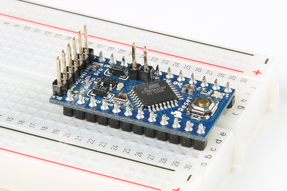
Using the Arduino Pro Mini 3.3V
Hardware Overview
Before we discuss hooking up the breakout, let’s go over some of the features of this board.
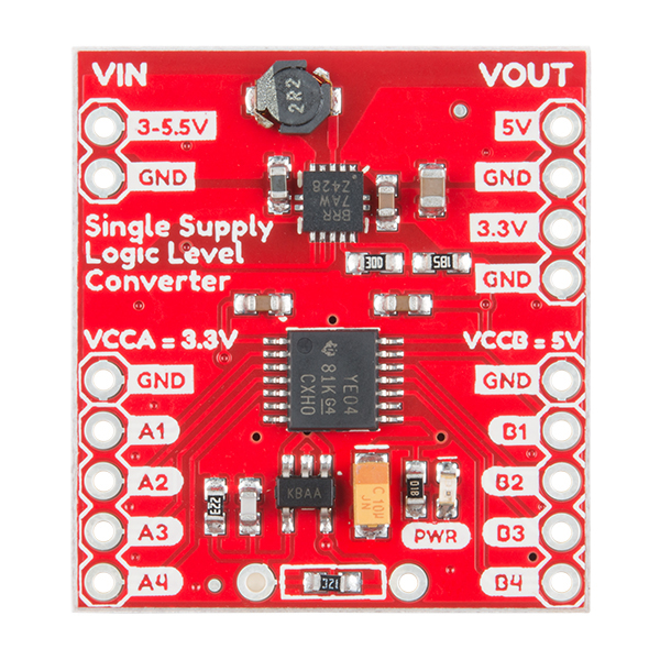
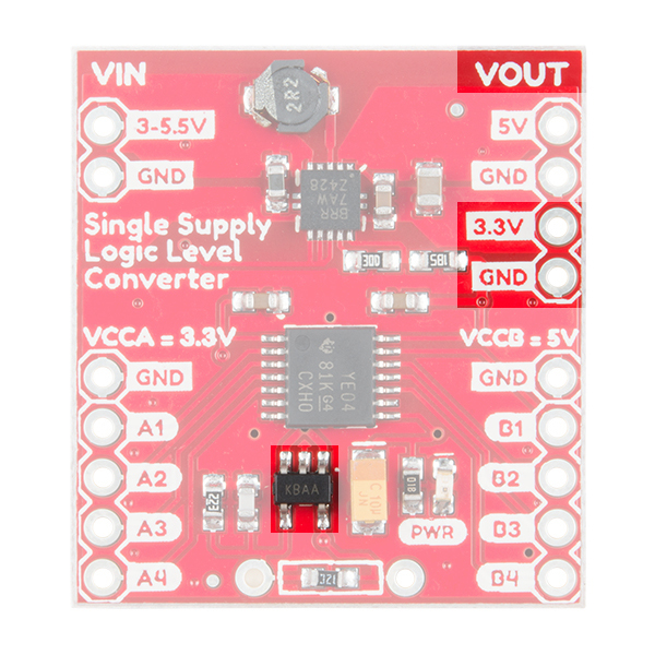
Pinout
The following table describes the pins that are broken out.
| Pin | Description |
|---|---|
| VIN | Input Supply Voltage (3V - 5.5V) |
| GND | Ground |
| VOUT, 5V | Boost Converter's Voltage Output Set to 5V |
| VOUT, 3.3V | Regulated Voltage Output Set to 3.3V (can be adjusted depending on resistor) |
| A1-A4 | Programmable VCCA Port for Lower TTL Logic Levels - Default = 3.3V |
| B1-B4 | VCCB Port for Higher TTL Logic Levels - Set to 5V |
Logic Level Shifter
The Single Supply Logic Level Converter breaks out Texas Instrument's TXB0104 module. The TXB0104 is a 4-bit, noninverting, bi-directional voltage-level translator with automatic direction sensing.
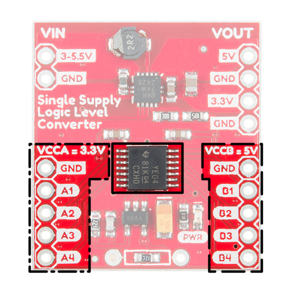
Each pin on this module is broken out for you to easily access ports A and B. Port A (A1-A4) is for low side TTL levels. This device's VCCA is set to 3.3V by default but can easily be programmable with a resistor to 2.5V and 1.8V. Port B (B1-B4) is for high side TTL levels. VCCB is hard wired to 5V. VCCA should not exceed VCCB. Depending on which voltage is chosen for VCCA the data rate may vary.
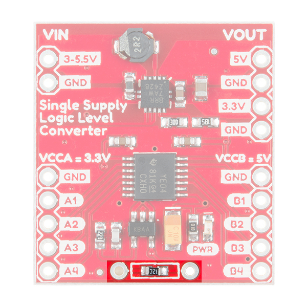
Adjusting the Lower Voltage Side (i.e. VCCA)
To adjust the reference voltage for the low side, you will need an associated resistor value to adjust the MIC5205's output voltage. Below is a table of calculated resistor values that can be used. For more information, check out equation 4-7 on page 11 of the datasheet.
| VCCA | Resistor Value |
|---|---|
| 3.3V | Default = 13kΩ |
| 2.5V | 22kΩ |
| 1.8V | 49kΩ |
Simply remove the default surface mount resistor with a blob of solder so that heat can be transferred to both terminals. Once heated, the surface mount resistor can be removed with tweezers or a gentle sweep of a soldering iron. Once removed, a resistor of your choice can be used to adjust the VCCA's reference voltage.


Power Supply and Voltage Regulator
The TPS61200 buck/boost converter on the Single Supply Logic Level Converter takes an input between 3V - 5.5V (most likely from your microcontroller's VCC pin) and regulates it to 5V. This output is also connected to the high side on VCCB for reference.

The output current of the TPS61200 depends on the input to output voltage ratio. The TPS61200 provides output currents up to 600 mA at 5V. The maximum average input current is limited to 1.5A. For more information, check out the datasheet.

The regulated 5V is then further regulated to 3.3V, which is connected to the low side on VCCA for reference. There is an option to reprogram VCCA's voltage using an external PTH resistor as explained earlier.
VCCA Reference Ground
⚡ Warning: The reference GND that you choose can affect the serial data being sent depending on how far your device is from the rest of the ground plane. You may notice some data not being sent correctly between your devices (like some gibberish or garbage data on a serial UART). It is recommended to use the GND pin by the lower VCCA side above the A1-A4 pins when you are referencing ground on the low side.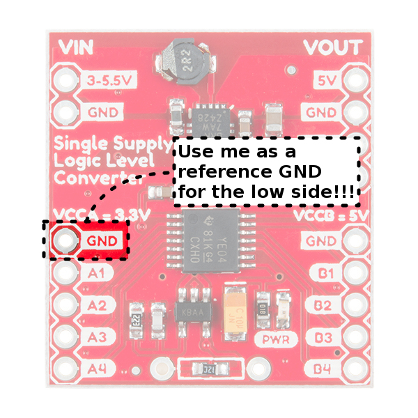
Timing Requirements
Not all logic level converters are the same! Compared to the lower cost bi-directional logic level converter with BSS138, the single supply logic level converter with TXB0104 is able to achieve higher data rates. The speed is dependent on the reference voltage that is used for the low side voltage on VCCA. This is indicated by the table below and was taken from the datasheet. For more information, check out page 8 of the datasheet.
| VCCA | Data Rate | Pulse Duration |
|---|---|---|
| 1.5V | 40 Mbps | 25 ns |
| 1.8V | 60 Mbps | 17 ns |
| 2.5V | 100 Mbps | 10 ns |
| 3.3V | 100 Mbps | 10 ns |
Hardware Hookup
Grab some straight header pins, break the pins apart, and solder them to the single supply logic level converter.
This would also be a good time to solder headers to the 3.3V/8MHz Arduino Pro Mini if you have not already done so!
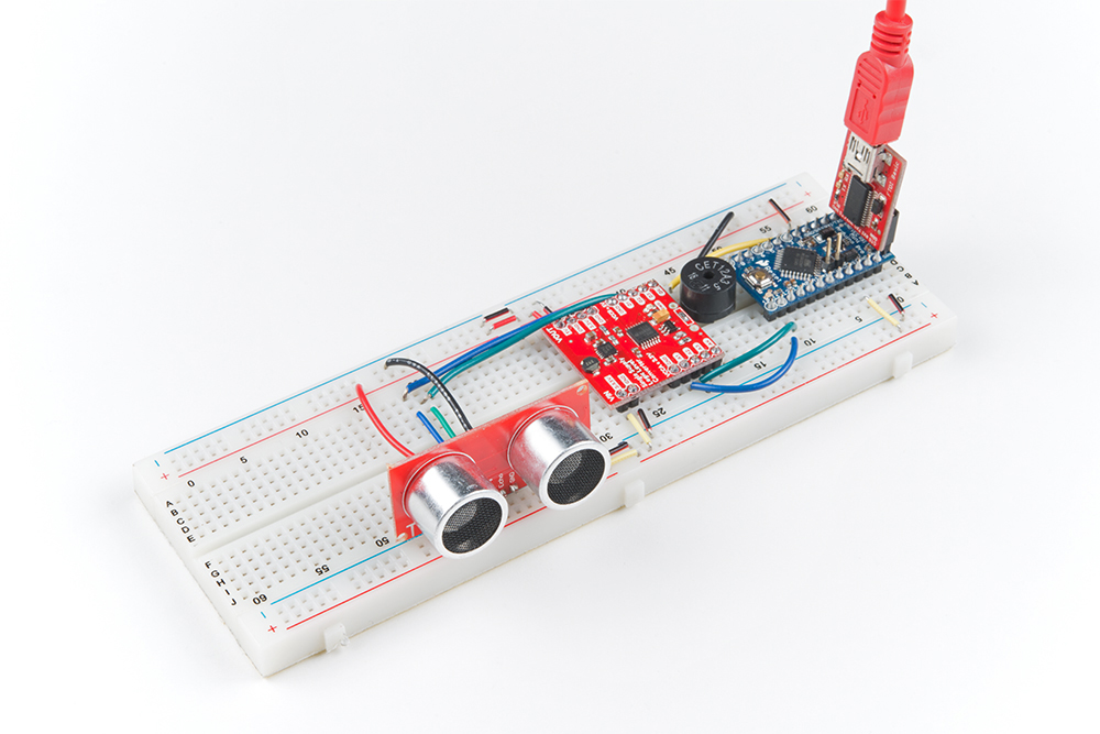
Circuit Diagram
Ready to start hooking everything up? Check out the circuit diagram below to connect the components together.

Example Code
The single supply logic level converter can be used to shift data in either direction. In this example, we are going to shift levels from a 3.3V Arduino microcontroller and a 5V sensor.
Level Shifting Between a 3.3V Microcontroller w/ 5V Sensor
Copy the code below and paste it into the Arduino IDE. Since we are using an Arduino Pro Mini 3.3V/8MHz, make sure that you are selecting the correct board. Additionally, make sure to have the correct COM port selected when uploading. When ready, upload the example code!
language:c
/*
Single Supply Logic Level Converter Hookup Guide

This project will beep continuosly with a frequency proportional
to distance. As objects get closer, the beep gets faster.

Hardware:
 HC-SR04 Ultrasonic Sensor
 Arduino Pro Mini 3.3V/8MHz
 SparkFun Single Supply Logic Level Converter
 Piezo Buzzer

*/


#define TRIG_PIN 10
#define ECHO_PIN 11
#define Beep 3

void setup() {
  Serial.begin (9600);
  pinMode(TRIG_PIN, OUTPUT);
  digitalWrite(TRIG_PIN, LOW);
  pinMode(Beep, OUTPUT);
}

void loop() {
  unsigned long t1;
  unsigned long t2;
  unsigned long pulse_width;
  float cm1;


  // Hold the trigger pin high for at least 10 us
  digitalWrite(TRIG_PIN, HIGH);
  delayMicroseconds(10);
  digitalWrite(TRIG_PIN, LOW);

  // Wait for pulse on echo pin
  while (digitalRead(ECHO_PIN) == 0 );

  // Measure how long the echo pin was held high (pulse width)
  // Note: the micros() counter will overflow after ~70 min
  t1 = micros();
  while (digitalRead(ECHO_PIN) == 1);
  t2 = micros();
  pulse_width = t2 - t1;

  // Calculate distance in centimeters.
  cm1 = pulse_width*0.034/2;
  if (cm1 >= 200 || cm1 <= 0){
    Serial.println("Out of range");
  }
  else {
    Serial.print(cm1);
    Serial.println(" cm");

    tone(Beep,528);
    delay(100);
    noTone(Beep);
    delay(cm1);


  }
}
After uploading, place your hand in front of the ultrasonic sensor. When your hand is within a certain range, the buzzer will begin beeping! As you move your hand toward the sensor, the buzzer will beep faster. Moving your hand away from the sensor will slow down the beeping until you are out of range.
Resources and Going Further
Now that you know how to get the Single Supply Logic Level Converter up and running, it's time to incorporate it into your own project!
For more on the Single Supply Logic Level Converter, check out the links below:
- Schematic (PDF)
- Eagle Files (ZIP)
- Datasheet
- GitHub Repo
- SFE Product Showcase: SparkFun Single Supply Logic Level Converter
Need some inspiration for your next project? Check out some of these related tutorials: