PCA9306 Level Translator Hookup Guide
 Toni_K
PCA9306 Overview
The PCA9306 is a dual bidirectional voltage translator for the I2C-bus and SMBus. It works at a range of voltages between 1.0 and 5.0V and doesn't require a direction pin to function.
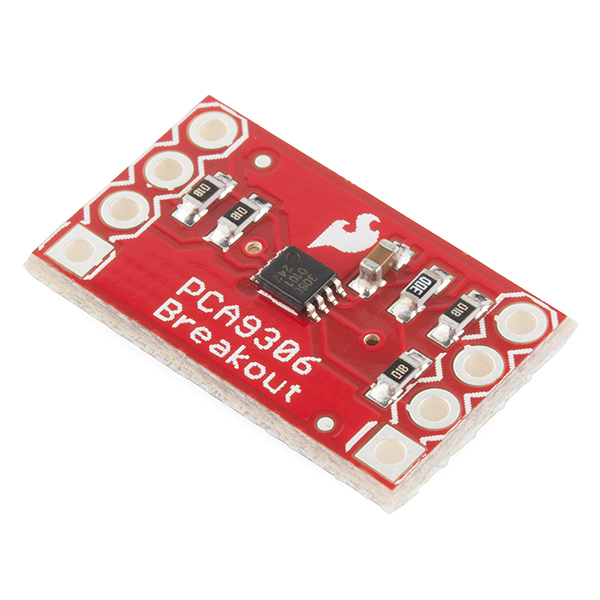
This is a great board for shifting voltages between sensors and your microcontroller.
Suggested Reading
These level converters are pretty easy to start using, but you may want to check out some of the additional reading material below if you are unfamiliar with logic level shifting or haven't worked with Arduino boards prior to this.
How to Solder: Through-Hole Soldering
What is an Arduino?
Logic Levels
I2C
Hardware Hookup
The breakout board has seven pins that need to be connected to function properly. VREF1, SCL1, and SDA1 all connect to your lower voltage part. VREF2, SCL2, and SDA2 connect to your higher voltage part. The GND pin needs to be connected to ground in your system. The final through-hole on the board labeled NC does not need to be connected to anything.
To connect the board, solder headers into the through-holes, and use jumper wires between devices. Or, you could just solder some hookup wire to all your boards.
For this example, we are going to use an Arduino Pro Mini 5V to connect to an HMC5883L magnetometer breakout board, which runs at 3.3V and communicates over I2C.
Connections:
HMC5883L → PCA9306
- 3.3V → VREF1
- SCL → SCL1
- SDA → SDA1
- GND → GND
PCA9306 → Pro Mini (5V)
- VREF2 → 5V
- SCL2 → A5
- SDA2 → A4
Here is a Fritizing diagram showing the actual connections between the HMC5883L, the PCA9306 breakout and the Pro Mini.
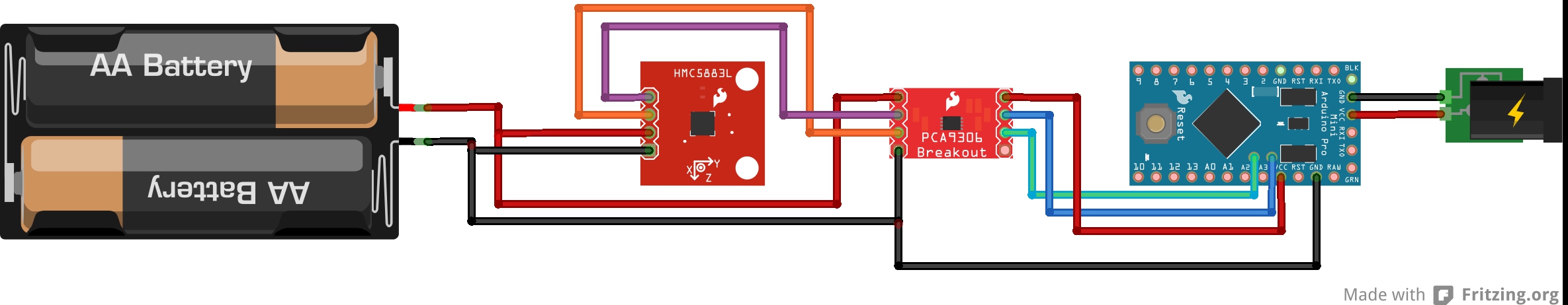
The diagram shows the HMC5883L running off of a 3V power supply, and the Pro Mini running off of a 5V barrel jack connector. Keep in mind your power supplies could be different than the ones pictured above (for example, using a LiPo battery instead of AA batteries), but you will still need to have a power supply for the lower voltage side of the system and a separate supply for the higher voltage side.
Once you have the boards physically connected, you are good to go! You don't need to use any special code with the PCA9306 board, and you can simply use any example sketch available for your sensors. In this case, we are using the example HMC5883.ino sketch.
Resources and Going Further
Now that you know how to use the logic level shifter, it's time to go and use this in your own project! Check out the additional resources below if you have any questions, or leave us feedback on the tutorial itself. Best of luck interfacing with all of your sensors!
Need more level shifting?! Check out these other level shifting hookup guides: