Raspberry Pi SPI and I2C Tutorial
 Byron J.,
  Shawn Hymel
 Introduction
There are many peripherals that can be added to a microprocessor over the I2C and SPI serial interfaces. These include atmospheric sensors, EEPROMS, and several types of display.
This tutorial will walk you through getting the I2C and SPI interfaces of your Raspberry Pi working. These interfaces aren't enabled by default, and need some extra configuration before you can use them.
Recommended Reading
Before we get started, you might want to review some related background material.
- I2C is a useful bus that allows data exchange between microcontrollers and peripherals with a minimum of wiring.
- SPI is a cousin of I2C with similar applications.
- For the C/C++ examples, we'll be using the wiringPi library to interface with these buses
- For the Python examples, we'll be using spidev for SPI and smbus for I2C.
Looking to get hands-on with Raspberry Pi?
We've got you covered!
Background & Software Setup
The Raspberry Pi has three types of serial interface on the GPIO header. You're probably already familiar with the UART serial port, which allows you to open a login session from a serial terminal application, such as PuTTY.
The other two serial interfaces are the Serial Peripheral Interface (SPI) and Inter-Integrated-Circuit bus (I2C). SPI on the Pi allows for up to two attached devices, while I2C potentially allows for many devices, as long as their addresses don't conflict.
Software Details
The software landscape for the Raspberry Pi has evolved considerably since the introduction of the Pi. Many different operating systems have been ported to the Pi, and the device driver infrastructure has also changed quite a bit.
For this tutorial, we'll be using a recent version of Raspbian (installed via NOOBS), and the wiringPi I/O library for C/C++ (or spidev/smbus for Python).
With the implementation of device tree overlays in Raspbian, some of the specific interface enablement details have changed. If you're working with an older install, it might be worth backing up your SD card, and starting with a fresh install.
OS and Library Install
If you're starting from scratch, with a blank SD card, you'll want to install Raspbian. If you've already got a working Raspbian system, skip ahead to the next section.
- Download the NOOBS image. As of this writing, it's at version 2.8.2.
- Follow the official installation instructions.
If you would like alternative ways to set up your Pi, please refer to the following tutorials:
Raspberry Pi 3 Starter Kit Hookup Guide
Headless Raspberry Pi Setup
Setting up a Raspberry Pi 3 as an Access Point
How to Use Remote Desktop on the Raspberry Pi with VNC
For those programming in C/C++, we recommend looking at the Raspberry gPIo to setup Wiring Pi. For your convenience, we have included the following instructions below.
Raspberry gPIo
C/C++ (Wiring Pi) Setup
git://git.drogon.net/wiringPi" is not available.
Wiring Pi is previously not included with early versions of Raspbian. This required users to download and install it. Luckily, Wiring Pi is included in standard Raspbian systems. If you are looking to update using a mirrored Wiring Pi with small updates to support newer hardware, we recommend checking out this GitHub repository.
You'll need git (may be installed by default). If git is not installed, enter the following into the command line.
language:bash
sudo apt-get install git-core
We highly recommend using Git to download the latest version. To check what version you have, enter the following command.
language:bash
gpio -v
If you receive an output similar to to the following with the Unknown17, you'll want to update WiringPi on a Raspberry Pi 4 or above.
language:bash
gpio version: 2.50
Copyright (c) 2012-2018 Gordon Henderson
This is free software with ABSOLUTELY NO WARRANTY.
For details type: gpio -warranty

Raspberry Pi Details:
  Type: Unknown17, Revision: 02, Memory: 0MB, Maker: Sony
    * Device tree is enabled.
    * --> Raspberry Pi 4 Model B Rev 1.2
    * This Raspberry Pi supports user-level GPIO access.
Enter the following to remove the wiringPi and configuration files.
language:bash
sudo apt-get purge wiringpi
Then type the following for the Pi to remove all locations that remember wiringPi.
language:bash
hash -r
As long as you have Git installed, these commands should be all you need to download and install Wiring Pi.
language:bash
git clone https://github.com/WiringPi/WiringPi.git
This will make a folder in your current directory called WiringPi. Head to the Wiring Pi directory.
language:bash
cd WiringPi
Then pull the latest changes from the origin.
language:bash
git pull origin
Then enter the following command. The ./build is a script to build Wiring Pi from the source files. This builds the helper files, modifies some paths in Linux and gets WiringPi ready to rock.
language:bash
./build
At this point, the library should work. Run the gpio command shown below to view some information about the wiringPi version and the Pi that it is running on.
language:bash
gpio -v
Entering the following command will draw a table illustrating the configuration for the pins in the 40-pin connector.
language:bash
gpio readall
The I2C and SPI interfaces each require some additional configuration and initialization, which we'll cover in later sections.
Python (spidev/smbus) Setup
Follow the Configure Your Pi section in the Python Programming Tutorial to set up Python 3 and install pip.
Python Programming Tutorial: Getting Started with the Raspberry Pi
Connecting To The Ports
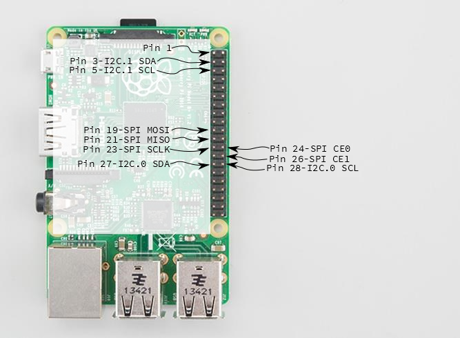
Before we get into the configuration and software examples, lets locate the pins used by each of these interfaces.
If you're directly connecting to the pins on the Pi, they're a little disorganized. I2C.1 is near one end, while SPI and I2C.0 are in the middle of the header. If you're connecting to these pins, be sure to count carefully.
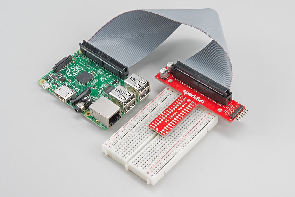
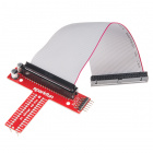
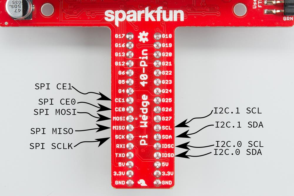
The Pi Wedge adapter PCB rearranges the pins, and labels them clearly. We'll be using the Wedge for the following examples.
SPI on Pi
Configuration
The SPI peripheral is not turned on by default. There are two methods to adjust the settings. To enable it, do the following.
Raspberry Pi Configuration via Desktop GUI
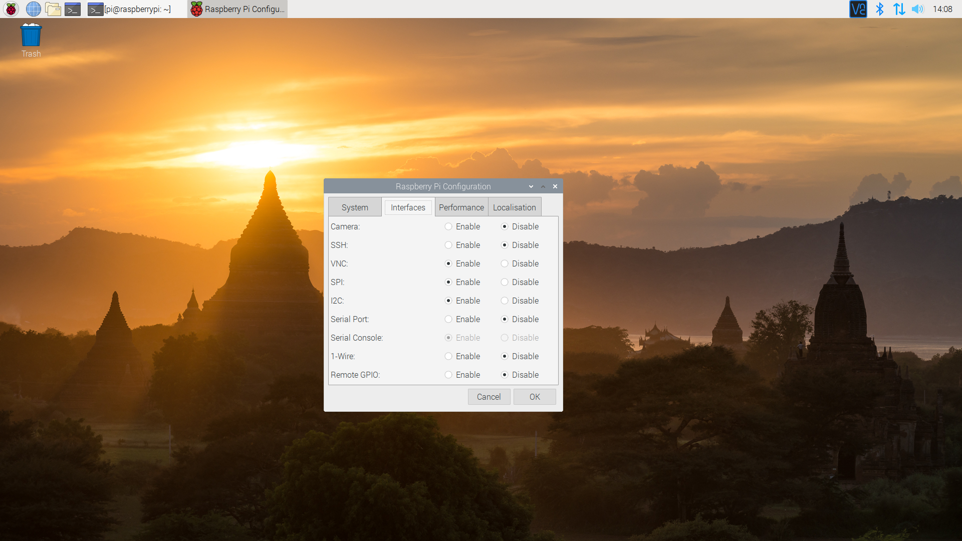
You can use the Desktop GUI by heading to the Pi Start Menu > Preferences > Raspberry Pi Configuration.

A window will pop up with different tabs to adjust settings. What we are interested is the Interfaces tab. Click on the tab and select Enable for SPI. At this point, you can enable additional interfaces depending on your project needs. Click on the OK button to save.
We recommend restarting your Pi to ensure that the changes to take effect. Click on the Pi Start Menu > Preferences > Shutdown. Since we just need to restart, click on the Restart button.
 |
 |
| Shutdown | Turn Off, Restart, Log Off |
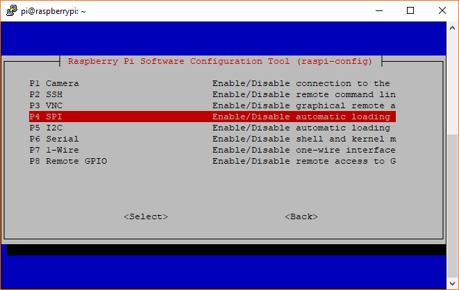
raspi-config Tool via Terminal
If you are using a terminal, you will need to:
- Run
sudo raspi-config. - Use the down arrow to select
5 Interfacing Options - Arrow down to
P4 SPI. - Select
yeswhen it asks you to enable SPI, - Also select
yesif it asks about automatically loading the kernel module. - Use the right arrow to select the
<Finish>button. - Select
yeswhen it asks to reboot.
The system will reboot. When it comes back up, log in and enter the following command
language:bash
ls /dev/*spi*
The Pi should respond with
language:bash
/dev/spidev0.0  /dev/spidev0.1
These represent SPI devices on chip enable pins 0 and 1, respectively. These pins are hardwired within the Pi. Ordinarily, this means the interface supports at most two peripherals, but there are cases where multiple devices can be daisy-chained, sharing a single chip enable signal.
Programming Example
Required Materials
- The 40-pin Pi Wedge.
- A Raspberry Pi B+ or Pi 2 Model B single board computer.
- A Solderless Breadboard.
- Some jumper wires.
- Headers of your choice.
- A Serial 7-Segment display.
The Serial 7-Segment display is particularly useful for testing serial interfaces, because it can accept command from a UART, SPI, or I2C. Make sure to solder header pins on the 7-segment display before wiring.
Hookup Table
The display was connected to the Pi, via the Pi Wedge, as follows.
| Raspberry Pi Signal | Serial 7-seg Signal |
| GND | GND |
| 3.3V | VCC |
| CE1 | SS (Shift Select) |
| SCK | SCK |
| MOSI | SDI |
| MISO | SDO |
The test hardware looked like this.

Sample C++ Program
language:c
/******************************************************************************
spitest.cpp
Raspberry Pi SPI interface demo
Byron Jacquot @ SparkFun Electronics>
4/2/2014
https://github.com/sparkfun/Pi_Wedge

A brief demonstration of the Raspberry Pi SPI interface, using the SparkFun
Pi Wedge breakout board.

Resources:

This example makes use of the Wiring Pi library, which streamlines the interface
to the the I/O pins on the Raspberry Pi, providing an API that is similar to the
Arduino.  You can learn about installing Wiring Pi here:
https://github.com/WiringPi/WiringPi/releases

The wiringPi SPI API is documented here:
https://projects.drogon.net/raspberry-pi/wiringpi/spi-library/

The init call returns a standard file descriptor.  More detailed configuration
of the interface can be performed using ioctl calls on that descriptor.
See the wiringPi SPI implementation (wiringPi/wiringPiSPI.c) for some examples.
Parameters configurable with ioctl are documented here:
http://git.kernel.org/cgit/linux/kernel/git/torvalds/linux.git/tree/Documentation/spi/spidev

Hardware connections:

This file interfaces with the SparkFun Serial 7 Segment display:
https://www.sparkfun.com/products/11629

The board was connected as follows:
(Raspberry Pi)(Serial 7 Segment)
GND  -> GND
3.3V -> Vcc
CE1  -> SS (Shift Select)
SCK  -> SCK
MOSI -> SDI
MISO -> SDO

To build this file, I use the command:
>  g++ spitest.cpp -lwiringPi

Then to run it, first the spi kernel module needs to be loaded.  This can be
done using the GPIO utility.
> gpio load spi
> ./a.out

This test uses the single-segment mode of the 7 segment display.  It shifts a
bit through the display characters, lighting a single character of each at a
time.

Development environment specifics:
Tested on Raspberry Pi V2 hardware, running Raspbian.
Building with GCC 4.6.3 (Debian 4.6.3-14+rpi1)

This code is beerware; if you see me (or any other SparkFun employee) at the
local, and you've found our code helpful, please buy us a round!

Distributed as-is; no warranty is given.
******************************************************************************/

#include <iostream>
#include <errno.h>
#include <wiringPiSPI.h>
#include <unistd.h>

using namespace std;

// channel is the wiringPi name for the chip select (or chip enable) pin.
// Set this to 0 or 1, depending on how it's connected.
static const int CHANNEL = 1;

int main()
{
   int fd, result;
   unsigned char buffer[100];

   cout << "Initializing" << endl ;

   // Configure the interface.
   // CHANNEL insicates chip select,
   // 500000 indicates bus speed.
   fd = wiringPiSPISetup(CHANNEL, 500000);

   cout << "Init result: " << fd << endl;

   // clear display
   buffer[0] = 0x76;
   wiringPiSPIDataRW(CHANNEL, buffer, 1);

   sleep(5);

   // Do a one-hot bit selection for each field of the display
   // It displays gibberish, but tells us that we're correctly addressing all
   // of the segments.
   for(int i = 1; i <= 0x7f; i <<= 1)
   {
      // the decimals, colon and apostrophe dots
      buffer[0] = 0x77;
      buffer[1] = i;
      result = wiringPiSPIDataRW(CHANNEL, buffer, 2);

      // The first character
      buffer[0] = 0x7b;
      buffer[1] = i;
      result = wiringPiSPIDataRW(CHANNEL, buffer, 2);

      // The second character
      buffer[0] = 0x7c;
      buffer[1] = i;
      result = wiringPiSPIDataRW(CHANNEL, buffer, 2);

      // The third character
      buffer[0] = 0x7d;
      buffer[1] = i;
      result = wiringPiSPIDataRW(CHANNEL, buffer, 2);

      // The last character
      buffer[0] = 0x7e;
      buffer[1] = i;
      result = wiringPiSPIDataRW(CHANNEL, buffer, 2);

      // Pause so we can see them
      sleep(5);
   }

   // clear display again
   buffer[0] = 0x76;
   wiringPiSPIDataRW(CHANNEL, buffer, 1);

}
When you built wiringPi, you might have noticed the statement about how to compile applications against it.
language:bash
NOTE: To compile programs with wiringPi, you need to add:
    -lwiringPi
to your compile line(s) To use the Gertboard, MaxDetect, etc.
code (the devLib), you need to also add:
    -lwiringPiDev
to your compile line(s).
Thus, we compile using the command.
language:bash
g++ spitest.cpp -l wiringPi -o spitest
Which generates an executable spitest. When we run ./spitest, it will exercise each of the segments of the display. It illuminates a segment in each digit for 5 seconds, before moving to the next segment. It takes about 40 seconds overall.
Sample Python Program
language:python
# spitest.py
# A brief demonstration of the Raspberry Pi SPI interface, using the Sparkfun
# Pi Wedge breakout board and a SparkFun Serial 7 Segment display:
# https://www.sparkfun.com/products/11629

import time
import spidev

# We only have SPI bus 0 available to us on the Pi
bus = 0

#Device is the chip select pin. Set to 0 or 1, depending on the connections
device = 1

# Enable SPI
spi = spidev.SpiDev()

# Open a connection to a specific bus and device (chip select pin)
spi.open(bus, device)

# Set SPI speed and mode
spi.max_speed_hz = 500000
spi.mode = 0

# Clear display
msg = [0x76]
spi.xfer2(msg)

time.sleep(5)

# Turn on one segment of each character to show that we can
# address all of the segments
i = 1
while i < 0x7f:

    # The decimals, colon and apostrophe dots
    msg = [0x77]
    msg.append(i)
    result = spi.xfer2(msg)

    # The first character
    msg = [0x7b]
    msg.append(i)
    result = spi.xfer2(msg)

    # The second character
    msg = [0x7c]
    msg.append(i)
    result = spi.xfer2(msg)

    # The third character
    msg = [0x7d]
    msg.append(i)
    result = spi.xfer2(msg)

    # The last character
    msg = [0x7e]
    msg.append(i)
    result = spi.xfer2(msg)

    # Increment to next segment in each character
    i <<= 1

    # Pause so we can see them
    time.sleep(5)


# Clear display again
msg = [0x76]
spi.xfer2(msg)
Save the program with a name like spitest.py, and run it with:
language:bash
python spitest.py
This will illuminate each segment in each character for 5 seconds before moving on to the next segment. It should take about 40 seconds for the whole program to run.
I2C on Pi
Configuration
The I2C peripheral is not turned on by default. There are two methods to adjust the settings just like the SPI. To enable it, do the following.
Raspberry Pi Configuration via Desktop GUI
You can use the Desktop GUI by heading to the Pi Start Menu > Preferences > Raspberry Pi Configuration.
A window will pop up with different tabs to adjust settings. What we are interested is the Interfaces tab. Click on the tab and select Enable for I2C. At this point, you can enable additional interfaces depending on your project needs. Click on the OK button to same.
We recommend restarting your Pi to ensure that the changes to take effect. Click on the Pi Start Menu > Preferences > Shutdown. Since we just need to restart, click on the Restart button.
|
|
| Shutdown | Turn Off, Restart, Log Off |
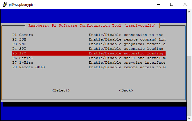
raspi-config Tool via Terminal
Like the SPI peripheral, I2C is not turned on by default. Again, we can use raspi-config to enable it.
- Run
sudo raspi-config. - Use the down arrow to select
5 Interfacing Options - Arrow down to
P5 I2C. - Select
yeswhen it asks you to enable I2C - Also select
yesif it asks about automatically loading the kernel module. - Use the right arrow to select the
<Finish>button. - Select
yeswhen it asks to reboot.
The system will reboot. when it comes back up, log in and enter the following command
language:bash
ls /dev/*i2c*
The Pi should respond with
language:bash
/dev/i2c-1
Which represents the user-mode I2C interface.
Utilities
There is a set of command-line utility programs that can help get an I2C interface working. You can get them with the apt package manager.
language:bash
sudo apt-get install -y i2c-tools
In particular, the i2cdetect program will probe all the addresses on a bus, and report whether any devices are present. Enter the following command in the command line. The -y flag will disable interactive mode so that you do not have to wait for confirmation. The 1 indicates that we are scanning for I2C devices on I2C bus 1 (e.g. i2c-1).
language:bash
i2cdetect -y 1
You will get an output from your Raspberry Pi similar to the output below.
language:bash
pi@raspberrypi:~/$ i2cdetect -y 1
     0  1  2  3  4  5  6  7  8  9  a  b  c  d  e  f
00:          -- -- -- -- -- -- -- -- -- -- -- -- --
10: -- -- -- -- -- -- -- -- -- -- -- -- -- -- -- --
20: -- -- -- -- -- -- -- -- -- -- -- -- -- -- -- --
30: -- -- -- -- -- -- -- -- -- -- -- -- -- -- -- --
40: -- -- -- -- -- -- -- -- -- -- -- -- -- -- -- --
50: -- -- -- -- -- -- -- -- -- -- -- -- -- -- -- --
60: 60 -- -- -- -- -- -- -- -- -- -- -- -- -- -- --
70: -- -- -- -- -- -- -- --
This map indicates that there is a peripheral at address 0x60. We can try to read and write its registers using the i2cget, i2cset and i2cdump commands.
Programming Example
Required Materials
- The 40-pin Pi Wedge.
- A Raspberry Pi B+ or Pi 2 Model B single board computer.
- A Solderless Breadboard.
- Some jumper wires.
- Header pins of your choice.
- An MCP4725 digital-to-analog converter.
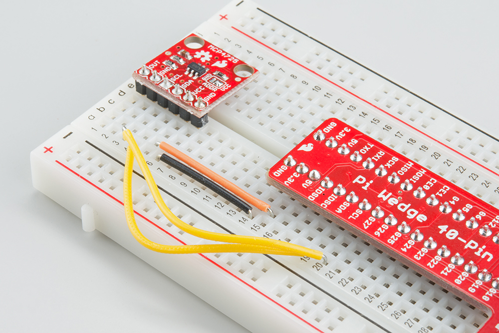
Hookup Table
The display was connected to the Pi, via the Pi Wedge, as follows.
| Raspberry Pi Signal | MCP4725 |
| GND | GND |
| 3.3V | VCC |
| SCL | SCL |
| SDA | SDA |
The test hardware looked like this.
Sample C++ Program
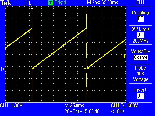
The following code writes successive values to the DAC, producing an sawtooth wave at its output pin.
language:c
/******************************************************************************
i2ctest.cpp
Raspberry Pi I2C interface demo
Byron Jacquot @ SparkFun Electronics>
4/2/2014
https://github.com/sparkfun/Pi_Wedge

A brief demonstration of the Raspberry Pi I2C interface, using the SparkFun
Pi Wedge breakout board.

Resources:

This example makes use of the Wiring Pi library, which streamlines the interface
the the I/O pins on the Raspberry Pi, providing an API that is similar to the
Arduino.  You can learn about installing Wiring Pi here:
https://github.com/WiringPi/WiringPi/releases

The I2C API is documented here:
https://projects.drogon.net/raspberry-pi/wiringpi/i2c-library/

The init call returns a standard file descriptor.  More detailed configuration
of the interface can be performed using ioctl calls on that descriptor.
See the wiringPi I2C implementation (wiringPi/wiringPiI2C.c) for some examples.
Parameters configurable with ioctl are documented here:
http://git.kernel.org/cgit/linux/kernel/git/torvalds/linux.git/tree/Documentation/i2c/dev-interface

Hardware connections:

This file interfaces with the SparkFun MCP4725 breakout board:
https://www.sparkfun.com/products/8736

The board was connected as follows:
(Raspberry Pi)(MCP4725)
GND  -> GND
3.3V -> Vcc
SCL  -> SCL
SDA  -> SDA

An oscilloscope probe was connected to the analog output pin of the MCP4725.

To build this file, I use the command:
>  g++ i2ctest.cpp -lwiringPi

Then to run it, first the I2C kernel module needs to be loaded.  This can be
done using the GPIO utility.
> gpio load i2c 400
> ./a.out

This will run the MCP through its output range several times.  A rising
sawtooth will be seen on the analog output.

Development environment specifics:
Tested on Raspberry Pi V2 hardware, running Raspbian.
Building with GCC 4.6.3 (Debian 4.6.3-14+rpi1)

This code is beerware; if you see me (or any other SparkFun employee) at the
local, and you've found our code helpful, please buy us a round!

Distributed as-is; no warranty is given.
******************************************************************************/

#include <iostream>
#include <errno.h>
#include <wiringPiI2C.h>

using namespace std;

int main()
{
   int fd, result;

   // Initialize the interface by giving it an external device ID.
   // The MCP4725 defaults to address 0x60.
   //
   // It returns a standard file descriptor.
   //
   fd = wiringPiI2CSetup(0x60);

   cout << "Init result: "<< fd << endl;

   for(int i = 0; i < 0x0000ffff; i++)
   {
      // I tried using the "fast write" command, but couldn't get it to work.
      // It's not entirely obvious what's happening behind the scenes as
      // regards to endianness or length of data sent.  I think it's only
      // sending one byte, when we really need two.
      //
      // So instead I'm doing a 16 bit register access.  It appears to
      // properly handle the endianness, and the length is specified by the
      // call.  The only question was the register address, which is the
      // concatenation of the command (010x = write DAC output)
      // and power down (x00x = power up) bits.
      result = wiringPiI2CWriteReg16(fd, 0x40, (i & 0xfff) );

      if(result == -1)
      {
         cout << "Error.  Errno is: " << errno << endl;
      }
   }
}
Build it and link it to wiringPi using the following command.
language:bash
g++ i2ctest.cpp -l wiringPi -o i2ctest
When you run i2ctest, the DAC will produce an analog sawtooth wave for a few seconds.
OUT pin Sample Python Program
language:python
# i2ctest.py
# A brief demonstration of the Raspberry Pi I2C interface, using the Sparkfun
# Pi Wedge breakout board and a SparkFun MCP4725 breakout board:
# https://www.sparkfun.com/products/8736

import smbus

# I2C channel 1 is connected to the GPIO pins
channel = 1

#  MCP4725 defaults to address 0x60
address = 0x60

# Register addresses (with "normal mode" power-down bits)
reg_write_dac = 0x40

# Initialize I2C (SMBus)
bus = smbus.SMBus(channel)

# Create a sawtooth wave 16 times
for i in range(0x10000):

    # Create our 12-bit number representing relative voltage
    voltage = i & 0xfff

    # Shift everything left by 4 bits and separate bytes
    msg = (voltage & 0xff0) >> 4
    msg = [msg, (msg & 0xf) << 4]

    # Write out I2C command: address, reg_write_dac, msg[0], msg[1]
    bus.write_i2c_block_data(address, reg_write_dac, msg)
Save the program with a name like i2ctest.py, and run it with the command:
language:bash
python i2ctest.py
You should see a sawtooth wave appear on the DAC output. If you connect an oscilloscope, you should get an image like the one shown in the C++ example. Note that Python is much slower than C/C++! The period of the sawtooth wave in the C++ example was around 100 ms whereas the period of the wave in the Python example was close to 1.8 seconds.
Be aware that SMBus is a protocol layer separate from but built on top of I2C. Some features of I2C may not be available with SMBus. For example, SMBus cannot handle clock stretching, so sensors that require it to communicate will not work with the smbus package.
To learn more about the smbus protocol, see the official kernel documentation.
I2C-0 on 40-pin Pi Boards
An Extra I2C bus?
As part of the B+ improvemets, the Raspberry Pi Foundation has standardized the interface to add-on boards, in what they call the "Hardware Added On Top" (HAT) specification. It standardizes the physical form factor for add-on boards, and includes a provision for the B+ to automatically identify and initialize HATs at startup. It uses an I2C bus to read a description from an EEPROM on the HAT, similar to cape identification on the Beagle Bone Black.
This capability has been carried forward on the A+ and Pi 2 Model B as well. This I2C bus is found on the ID_SC and ID_SD pins (pins 27 and 28 of the 40-pin connector) - but before you get too excited about adding peripherals on that bus, observe the note in the schematic for that port.
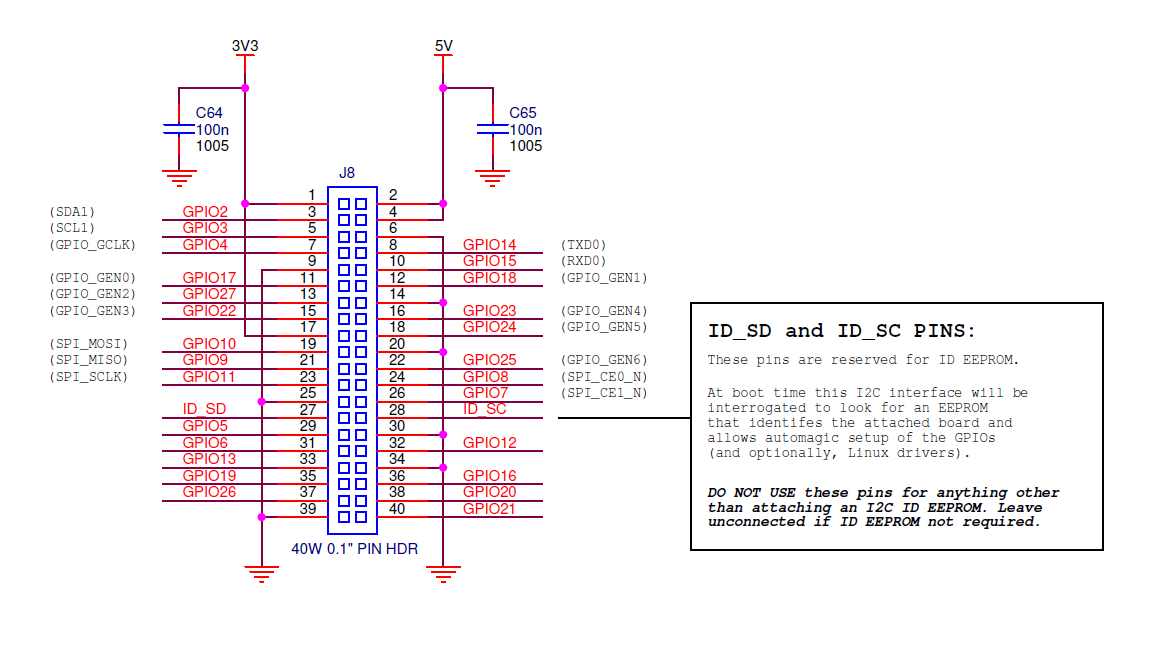
This is further clarified in the HAT design guide
On a Model B+, GPIO0 (ID_SD) and GPIO1 (ID_SC) will be switched to ALT0 (I2C-0) mode and probed for an EEPROM. These pins will revert to inputs once the probe sequence has completed.
The only allowed connections to the ID_ pins are an ID EEPROM plus 3.9K pull up resistors. Do not connect anything else to these pins!
It's only there to talk to EEPROMs at addresses 0x50 during boot time. User access at runtime is problematic. If you want a general purpose I2C bus on the B+, you'll need to use I2C-1, on pins 3 and 5 of the 40-pin connector, marked SDA and SCL on the Pi Wedge.
Enabling I2C-0
I2C-0 is disabled by default. To enable it, you'll need to manually edit the configuration file.
Edit /boot/config.txt, and add the following line. If you previously used raspi-config to enable I2C-1 and SPI, you'll see similar entries near the bottom of the vile.
language:bash
dtparam=i2c_vc=on
With that enabled, restart your Pi (sudo reboot). When it's back up, you'll know it's been activated if you've got a filesystem node at /dev/i2c-0.
EEPROM Diagnostic Tools
Alongside the HAT design guide, there is a directory with some software tools for working with HAT EEPROMs. To use them, download them and then make them from the command line.
We'll explore how they're used below.
Testing I2C-0
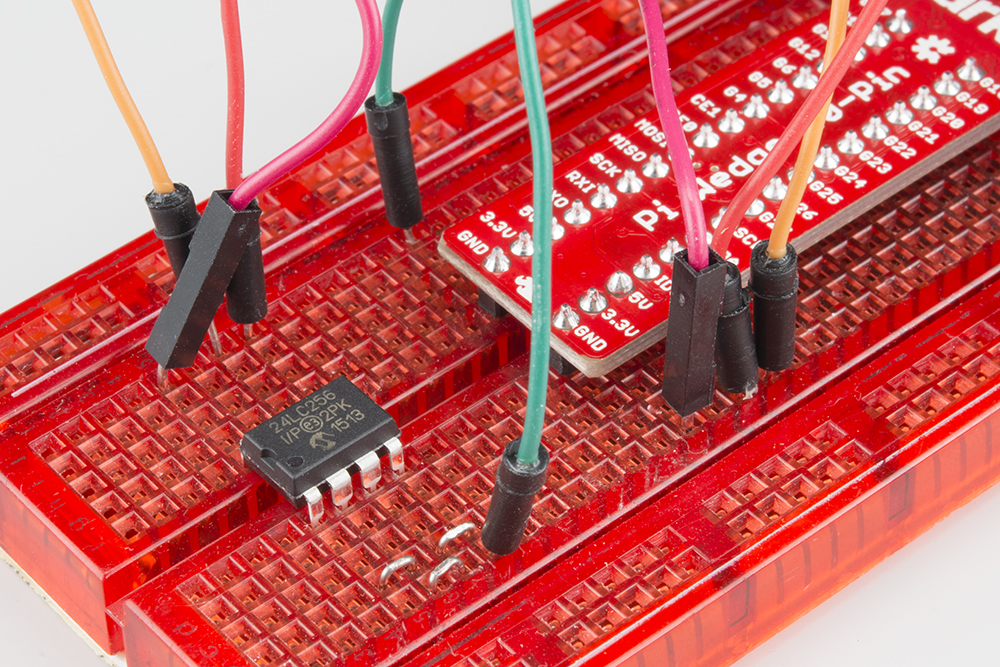
With the information above, we grabbed a 24LC256 EEPROM chip, and wired it to our Pi. We strapped all of the address pins to ground, which puts it at address 0x50, which we were able to confirm with i2cdetect.
Pull the EEPROM utilities mentioned above. The file test_settings.txt is a human-readable example of an EEPROM file. For testing purposes, we edited this file, changing the vendor and product fields to relevant information.
The text file itself needs to be processed into a binary format before it can be written to the EEPROM. The eepmake utility handles this conversion.
language:bash
./eepmake  test_settings.txt test.eep
With the binary test.eep in hand, it can be programmed using the eepflash.sh script. It takes a number of parameters, which are explained if you run it with the -h flag. When writing the EEPROM, you'll also have to approve of the operation by typing the full word yes when it prompts (a simple y is not acceptable). eepflash.sh will print out the status of the write -- the 118 bytes written matches the length of the test.eep file we generated above.
language:bash
sudo sh ./eepflash.sh -w -f=test.eep -t=24c256
This will disable the camera so you will need to REBOOT after this process completes.
This will attempt to write to i2c address 0x50. Make sure there is an eeprom at this address.
This script comes with ABSOLUTELY no warranty. Continue only if you know what you are doing.
Do you wish to continue? (yes/no): yes
Writing...
0+1 records in
0+1 records out
118 bytes (118 B) copied, 2.33811 s, 0.1 kB/s
Done.
As advised by that output, it is time to reboot.
When the system comes back up, you should have some new filesystem nodes at /proc/device-tree/hat
language:bash
pi@raspberrypi /proc/device-tree/hat $ ls -al
total 0
drwxr-xr-x  2 root root  0 Oct 27 20:16 .
drwxr-xr-x 15 root root  0 Oct 27 20:16 ..
-r--r--r--  1 root root  4 Oct 27 20:16 name
-r--r--r--  1 root root 21 Oct 27 20:16 product
-r--r--r--  1 root root  7 Oct 27 20:16 product_id
-r--r--r--  1 root root  7 Oct 27 20:16 product_ver
-r--r--r--  1 root root 37 Oct 27 20:16 uuid
-r--r--r--  1 root root 24 Oct 27 20:16 vendor
If we inspect the contents of those notes, we see the values that we put in the test_settings.txt file:
language:bash
pi@raspberrypi/proc/device-tree/hat $ cat vendor
SparkFun Electronics

pi@raspberrypi /proc/device-tree/hat $ cat product
EEPROM Testing
Troubleshooting
If you've gone through raspi-config and enabled the SPI/I2c from 'Advanced Options', yet the devices are not in the device tree, don't lose hope. There are two files that should be examined. We found that somtimes the raspi-config utility doesn't solve the problem, depending on what version of Pi, where raspbian was sourced from, and when the last update has occurred.
Check /boot/config.txt
Sometimes the raspi-config tool will incorrectly edit /boot/config.txt while selecting the advanced settings. What happens is an erroneous control-char is placed in the file.
hdmi_force_hotplug=1
config_hdmi_boost=4
overscan_left=24
overscan_right=24
overscan_top=16
overscan_bottom=16
disable_overscan=0^Mdtparam=spi=on
dtparam=i2c_arm=on
^M character. Fix the line breaking in the file so it looks something like this:
hdmi_force_hotplug=1
config_hdmi_boost=4
overscan_left=24
overscan_right=24
overscan_top=16
overscan_bottom=16
disable_overscan=0
dtparam=spi=on
dtparam=i2c_arm=on
Check /etc/modules
If they are not present, add the following to the end of /etc/modules
i2c-dev
Reboot the System
After checking the files, reboot by issuing sudo reboot or sudo shutdown -r now.
Resources and Going Further
For digging deeper into the concepts covered in this tutorial, please see the following:
- If you're really curious about the nitty-gritty internal details of I2C and SPI, you might want to read the source code of Wiring Pi, which you can clone from here.
- Additionally, you can learn about the Linux underpinnings of these interfaces documented at kernel.org. The SPI documentation seems to be more complete than its I2C sibling.
- If the example code here isn't working, you should check for updated versions on the 40-pin Pi Wedge GitHub Repository.
- The way that I2C and SPI devices are enabled in Raspbian has changed significantly in recent revisions. This forum post explains how to re-enable the interfaces if they disappeared in an upgrade.
- The HAT specifications and related information are hosted on GitHub. If you're designing a HAT, you'll want to start by reading the HAT Design Guide, and possibly perusing the B+ addons forum.
- Filezilla is a convenient FTP & SFTP client, which is useful for getting files to and from a Pi.
- PuTTY is a terminal program that has serial, telnet and SSH modes.
- The Pi gPIo tutorial explains how to use the digital I/O pins on your Pi.
- The Pi Wedge gives you a convenient way to access the SPI and I2C interfaces on your Pi.
For more information about the Raspberry Pi and the software described here, please visit their sites.
- The Raspberry Pi Foundation
- The Pi Foundation's B+ Addons forum.
- The Pi Foundation's GitHub repository for the Raspberry Pi B+ HATs.
- The eLinux.org Raspberry Pi peripherals guide
- WiringPi
- spidev
- RPi.GPIO module
- Some notes about increasing the available current from the B+ USB ports.
For more information on connecting hardware to the Raspberry Pi and inspiration for projects, check out the following guides:
Building Large LED Installations
Bark Back Interactive Pet Monitor
Raspberry gPIo
Raspberry Pi Zero Helmet Impact Force Monitor
Using Flask to Send Data to a Raspberry Pi
Python Programming Tutorial: Getting Started with the Raspberry Pi
Graph Sensor Data with Python and Matplotlib
Python GUI Guide: Introduction to Tkinter
If you have any problems or questions, our technical support department can help. Please don’t hesitate to contact us. We also love to hear about your projects!