micro:arcade Kit Experiment Guide
Experiment 2: Button Reaction Timer
Introduction
You learned about reading button presses in Experiment 1 and event blocks. But, there is a bit of a problem with reading buttons that way... Events cannot be used as a variable in a simple way (similar to just reading a pin on its own). If for some reason you want to be able to read a combination of blocks at one time, or in this case use the state of a button with some other type of logic you actually need to use the Button variables that come with the gamer:bit extension. You will be building a reaction timer to test how sharp your wits really are!
We will also be adding an external button to controller:bit to give it a bit of an arcade feel!
Parts Needed
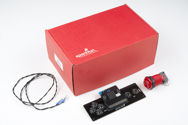
You will need the following parts:
- 1x micro:bit Board (Not Included with Kit)
- 1x micro-B USB Cable (Not Included with Kit)
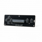
- 1x controller:bit carrier board
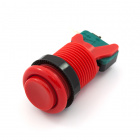
- 1x Arcade Button
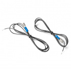
- 2x Spade Wire Connectors
Didn't get the kit? Have no fear! Here are the parts you will need to complete this experiment. You may not need everything though depending on what you have. Add it to your cart, read through the guide, and adjust the cart as necessary.
micro:bit Board
DEV-14208Suggested Tools
- Ball point pen
- Hobby knife or scissors
Suggested Reading
- Getting Started with the micro:bit - Basic hookup and programming of the micro:bit
Introduction to the Arcade Buttons
The classic arcade button! Oh how we love them.
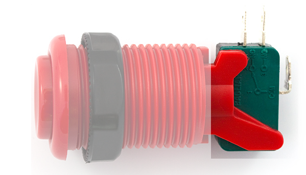
The arcade buttons work two ways as either a normally closed (NC) switch or as a normally open (NO) switch. That is to say that you can pick whether pressing the button completes, or closes the circuit. Or, breaks the circuit from a closed, or "on" state.
The back of each button has a the actual switch with 3 tabs. One is common or "COM" which you will always use and then either "NO" or "NC". In this case, we will be using Normally Open, but there are times where you could use Normal Closed as well.
Hardware Hookup
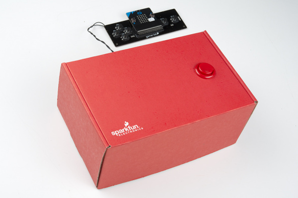
You will be hooking up one of the arcade buttons to the UP direction pad. You can then mount the button in a cardboard box or any other panel you like. The cardboard box that the kit came in is a good stand in for now!!
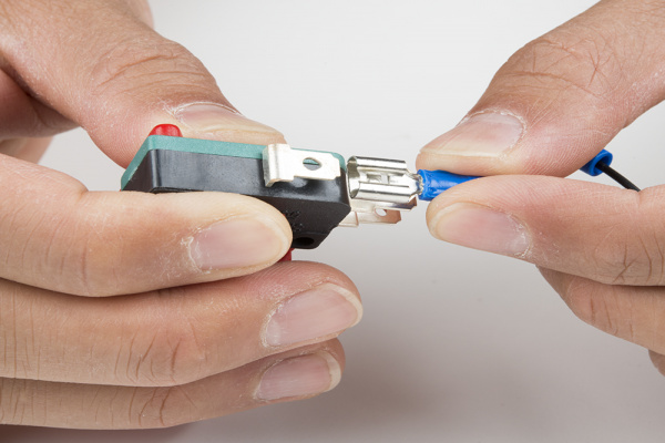
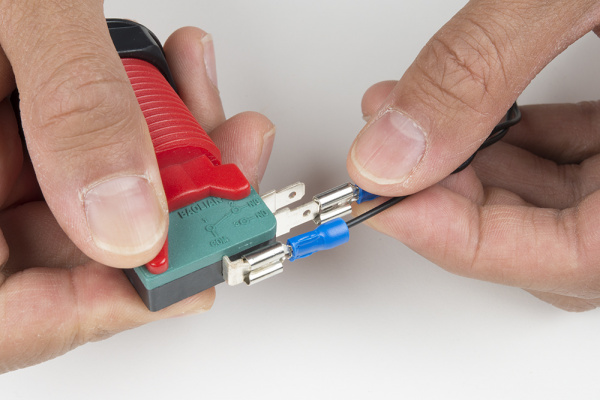
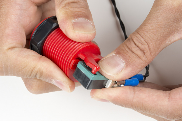
We will start out by adding the disconnect wires to the button. Start by connecting one wire to the Common (COM) pin on the button. The disconnects should slide over the tabs on the buttons snugly.
Next, for each button add another wire to the "NO" tab, on the button, you should have two wires connected to it at this point.
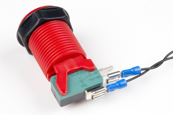
The image below shows the quick disconnects added to the terminals of the microswitch.
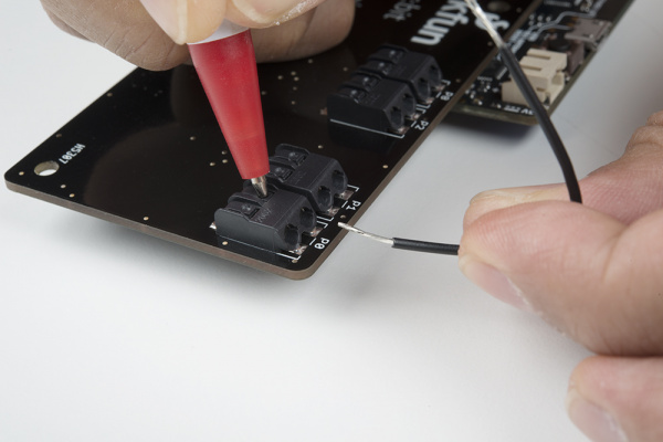
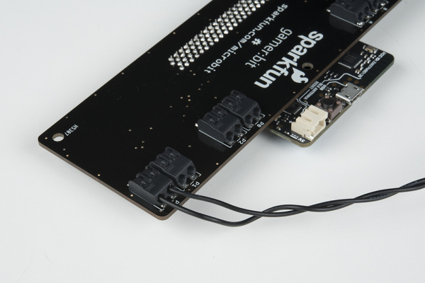
Finally, connect each set of wires to its corresponding poke-home connector by pressing down on the tab of the connector with a ballpoint pen and inserting the bare wire end. It doesn't matter what wire goes where in this wiring configuration as long as each wire is connected to pin P0 and P1.
As the poke-home connector is being pressed down, insert the wire into the connector as shown below.
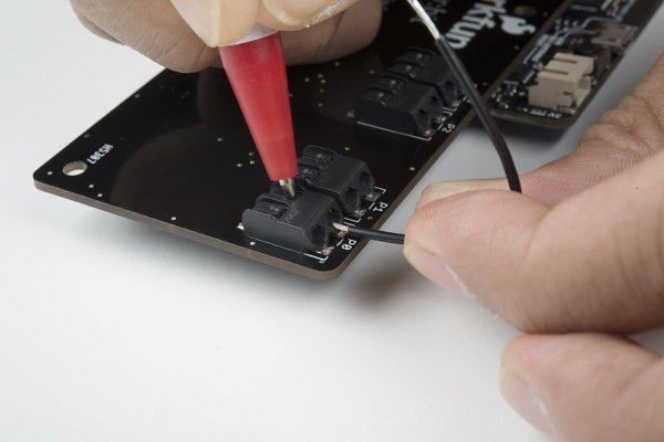
Once the wire has been inserted sufficiently into the poke-home connector, pressure from the ballpoint pen on the tab may be removed. The connector will actually hold it tight until you want to remove it. Below shows an image of the wires connected to P0 and P1.
The buttons themselves are designed to be mounted to a panel made of plywood, plastic, or even through a piece of cardboard. For this project we used the box that the kit came in as a great cabinet for your reaction timer.
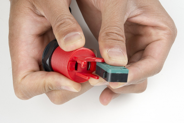
To start, we need to remove the microswitch from the bottom of the button by carefully prying it out of the mounting bracket. This isn't held in place with any hardware, just molded plastic, so be careful not to break anything. With the green side of the microswitch facing toward you, you will need to push the one of the plastic pins holding it in place. Gently twist the microswitch counterclockwise with your left hand while holding the concave button with your right hand.
Once the plastic pins is out of one of the holes, rotate the microswitch away from the pin as shown in the image below.
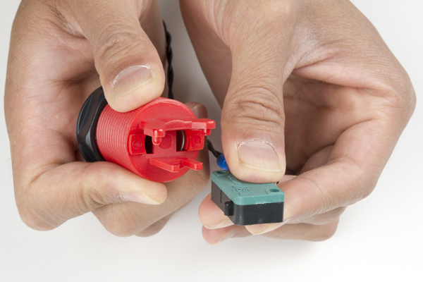
Finally, slide the microswitch out by moving it out of the second molded pin.
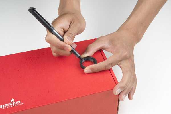
To mount the concave button, we will also need to cut a hole the cardboard box. You will need to unscrew the black ring from the concave button. In this experiment, we will be mounting the button on the top right side of the box. We can use the black ring that is attached to the concave button as a guide to cut the 1 1/8" hole. Using a pen, draw the mounting hole.
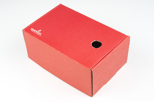
Using a craft knife or pair of scissors, cut a hole inside of the lines. Make sure to not cut too much of the cardboard box.
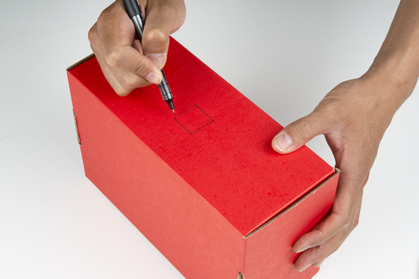
Additionally, draw about a 1" square hole on the front of the box for the wires. The square was placed in the middle for the purpose of this experiment.
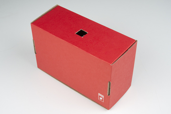
Cut the square out using the craft knife or pair of scissors.
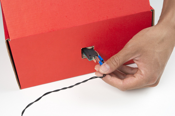
Insert the microswitch with wires through the square hole.
At this point, we can insert the concave button through the hole and thread the nut back onto the button from the bottom. The cardboard will be sandwiched between the concave button and the threaded nut. Finally, reattach the microswitch to the bottom of the concave button.
Now, give it a good mash to test it and make sure it will hold up!
Running Your Script
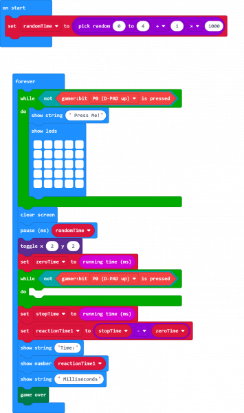
Now, you can either download the following example script below and drag and drop it onto your micro:bit, or use it as an example and build it from scratch in MakeCode.
Code to Note
Let’s take a look at the code blocks in this experiment.
RandomTime
We create a variable called randomTime and store a value that produces a random number between 1 and 5 seconds. This will be the random time it takes that a person needs to wait before the LED will turn on so it is harder to "game" the system or cheat their reaction time.
We produce that random number using the random number to block which produces a random number between 0 and a give value, we set it to 4. To make the range between 1 and 5 seconds we added 1 and multiplied that value by 1000.
While Not Gamer:bit Pressed
Once the program starts we need it to wait until the button is pressed by the person playing. To put the program in "limbo" we use a while block that reads the opposite of the gamer:bit pressed block. In other words... while the button is NOT being pressed, the program will do nothing. We use this twice; once at the beginning to start the game and a second time to capture the reaction timing.
Toggle X Y
To turn the LED in the center of the LED array on we use the Toggle X Y block. This will toggle the LED at a given X/Y coordinate. In terms of the the LED, a "toggle" changes its state from the one that it currently is in. So toggling from OFF is to turn something ON.
ZeroTime
To keep track of a reaction time we need two values to compare; a starting point and a stopping point. We capture the staring point by creating a variable called zeroTime and setting it to running time. The running time block returns the number of milliseconds that the micro:bit has been powered up and running.
StopTime
Once the button is pressed we need to capture that current time. When the button is pressed it releases the program from the while block and captures the current time again and stores it to the stopTime variable. This is done the same way as the zeroTime variable.
ReactionTime
When we have the two different variables zeroTime and stopTime, we can calculate the player's reaction time. The reaction time is the difference between the two.
Show String / Number
We display the readout of the player's reaction time to the player once they have finally reacted. The show string block allows you to display text across the LED array. The show number block does the same thing, but for a number.
Game Over
The game over block is an animation block found under the game:bit toobox drawer of MakeCode. It does a little animation, prints out "Game Over", and then a score if you are using it.
What You Should See
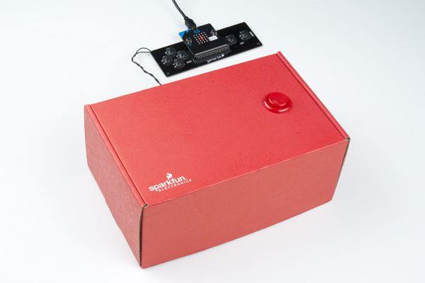
Once your code is loaded to the micro:bit, you should see text scroll by that says "Push Me!". Press the button and the screen will go blank. Once the single LED lights up, press the button again as quickly as possible. Your reaction time will then be displayed followed by a game over sequence.
Troubleshooting
Game doesn't start right away - You have to wait for the text to finish scrolling by before the game starts. Make sure to press down on the button before the text finishes scrolling.
Doesn't read my button press - Make sure that you are hooked up to the correct button on the controller:bit and that all wires are securely fastened to both the button and the board.
Reads a constant button press - You have the button wired to NC (Normally closed) and so it is constantly being pressed, change the connections on the back of the button to NO (Normally Open).
