micro:arcade Kit Experiment Guide
 D___Run___,
  bboyho
 Introduction to the micro:arcade Kit
We love games! We love writing games, building games and yes, even building game consoles. So we want to introduce to you the micro:arcade kit for the micro:bit!
The kit includes our controller:bit carrier board for the micro:bit, which gives you access to a number of pins through the form of buttons in a classic game controller layout. But, that isn't all!
It's one thing to design a "game controller," but what about building a console? A joystick, buttons to mash...the things that make us hard-core arcade fans drool and daydream. This kit is designed for you! The kit includes all of the parts you need to take this lowly controller breakout to a pinball wizard's dream!
Included Materials
| micro:climate Kit SKU | Revision History |
|---|---|
| KIT-16403 | - Minor revision on the controller:bit (formerly known as the gamer:bit) which includes the Qwiic connector and surface mount edge connector. - Switch to 2xAAA battery holder with a built-in switch. |
| KIT-14218 | Initial release. |
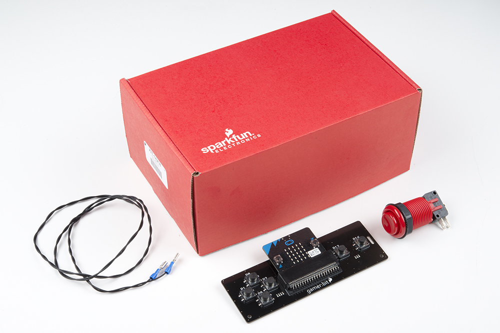
Below is all the parts included in the SparkFun micro:arcade kit.
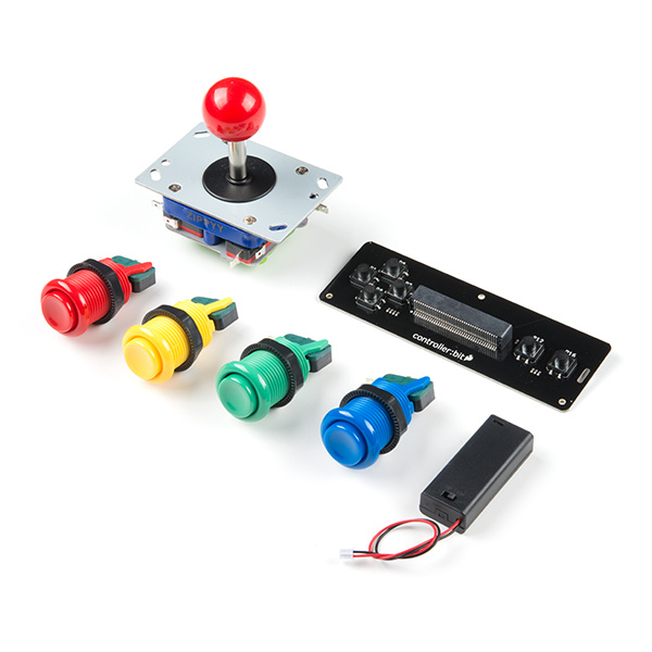
The kit includes the following parts:
- 1x - SparkFun controller:bit — The carrier board for the micro:bit that turns it into a handheld controller, game or other tool.
- 1x - Arcade Joystick — Old-school arcade joystick that uses digital switched for directions.
- 1x - Red Concave Button — Mash away!
- 1x - Blue Concave Button — Jump!
- 1x - Yellow Concave Button — Game over!
- 1x - Green Concave Button — For firin' the laser!
- 1x - micro:bit Battery Holder — Unique 2xAAA battery holder built specifically for the BBC micro:bit
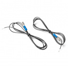
- 16x - Spade Connector Wires — 24 AWG 3 ft wires with a female insulated spade connector at one end and a braided wire lead at the other to connect the arcade buttons and joystick to the controller:bit
- 1x micro:bit
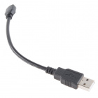
- 1x Micro-B USB Cable
- 2x AAA Batteries
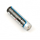
750 mAh Alkaline Battery - AAA
PRT-09274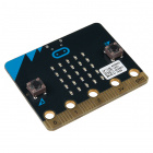
micro:bit Board
DEV-14208How to Use This Guide
We wanted to note that this guide is designed to get you started with the controller:bit board and the SparkFun micro:arcade kit in a straightforward and simple way. We demonstrate each component's functionality and the corresponding code to make it work.
While you explore this guide, we urge you to take your time and tinker with the sensors, code and the ideas shared to build something tailored to your application and creativity. Our goal is to get you enough information and know-how to make you dangerous and then release you into the wild.
Be sure to share your projects with us over Twitter or Facebook! We are excited to see you Start Something!
Suggested Reading
Before continuing with this guide, we recommend you be somewhat familiar with the concepts in the following tutorials:
What is a Circuit?
Getting Started with the micro:bit
Open Source!
All of our experiments and guides are licensed under the Creative Commons Attribution Share-Alike 4.0 Unported License. Feel free to remix and reuse our work. But please, share the love and give us attribution for our hard work!
To view a copy of this license visit this link, or write: Creative Commons, 171 Second Street, Suite 300, San Francisco, CA 94105, USA.
Hardware Overview
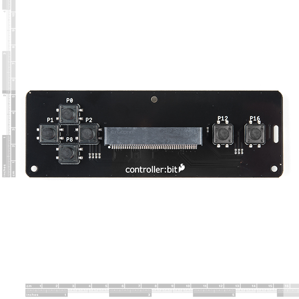
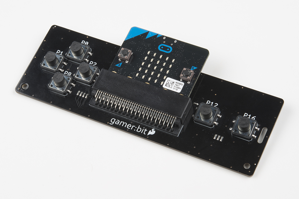
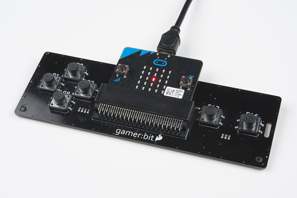
The controller:bit (formerly known as the gamer:bit) is a carrier board for the micro:bit. It is similar to an Arduino shield by adding functionality to the micro:bit without the hastle of a number of other boards, components, and all of those jumper wires connected to a breadboard.
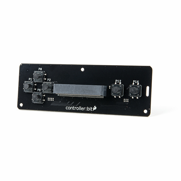
In this case, the controller:bit takes your normal run of the mill micro:bit and turns it into a fully functional game system with a few extra parts to take your game experience to the next level. Let's take a closer look at the controller:bit!
 |
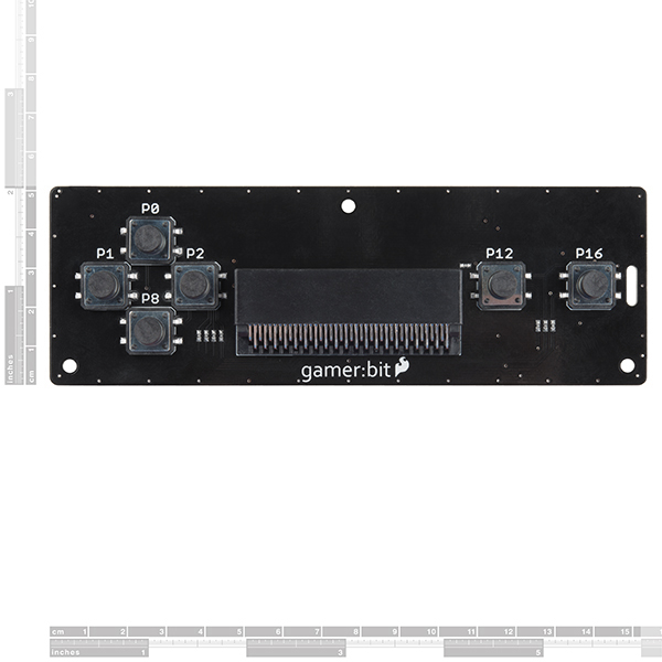 |
| Qwiic controller:bit [ DEV-16129 ] | gamer:bit [ DEV-14215 ] |
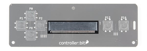
Edge Connector
The controller:bit connects to the micro:bit via an edge pin connector in the center of the board. This makes it handy to swap out micro:bits for programming, but also gives reliable connections to all of the different pins on the micro:bit. Make sure that you insert the micro:bit correctly with the LED array facing up!
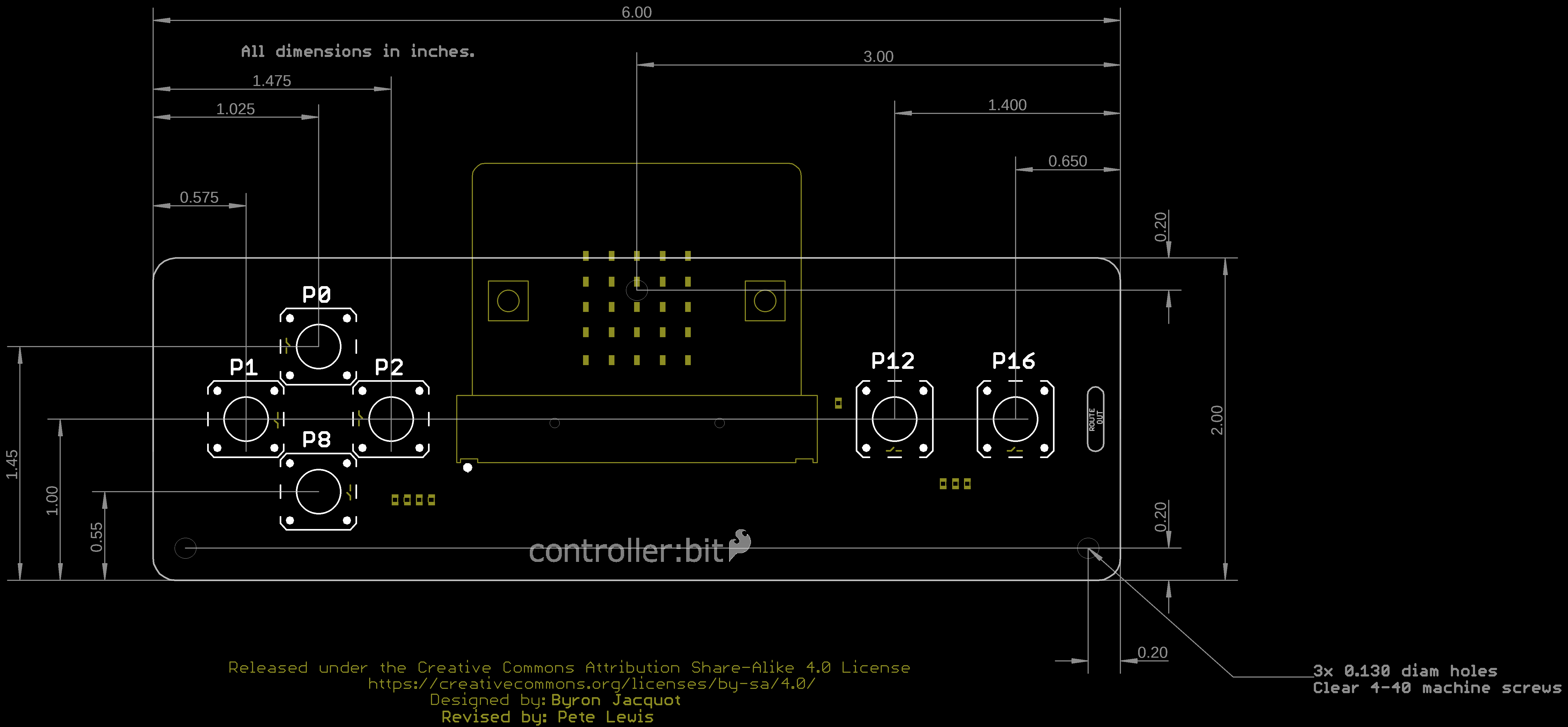
Direction Buttons
The controller:bit is designed around a classic game controller which means ther is a familiar "D Pad" style button layout on the left hand side of the board. The pins that each button controls are labeled on the board.
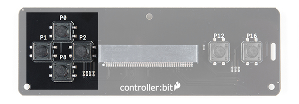
- UP => P0
- RIGHT => P1
- DOWN => P8
- LEFT => P2
Action Buttons
There are two action buttons.
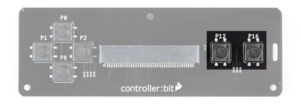
Let's name them X and Y buttons. Sorry to those used to the classic style naming, but A and B are already referenced with the buttons on the micro:bit. These buttons have no specific use other than what you program them to be. They are connected to the following pins:
- X (LEFT FUNCTION) => P12
- Y (RIGHT FUNCTION) => P16
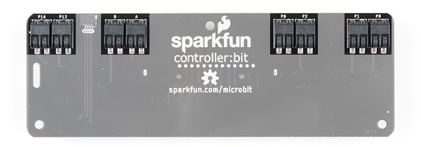
Poke-Home Connectors
On the back of the controller:bit you will notice some odd plastic connectors. These are called poke home connectors. Each one corresponds to a button on the back of the board and are labeled as such. You will end up using these to connect your external components to controller:bits buttons. Each button has two pins to it, one for each wire to connect to the button and component.
With that, you are ready to start! Are you a user? We hope you have your chips, energy drink and eye drops because this is going to be a marathon!
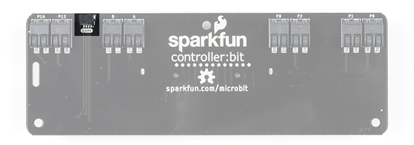
Qwiic Connector
On v2.0 of the board, you'll notice the additional qwiic connector attached if you decide to connect a qwiic enabled gator device. For the scope of this tutorial, we will be focusing on the rest of the board.
Hardware Overview
The board is about 2.00" x 6.00". THere are three mounting holes on the board if you decide to make an enclosure or secure the board to a panel.
Installing the gamer:bit Extension for Microsoft MakeCode
To make the most out of the gamer:bit with the least amount of coding, use the MakeCode extension we wrote for the gamer:bit board.
Extension?
If you have used Arduino before, you probably know about a thing called a library; which is a collection of code that extends the functionality of the core programming language. MakeCode extensions work the same way.
There are some amazing differences between Arduino libraries and MakeCode extensions. One of them is that MakeCode extensions include JavaScript functions, which you can use when programming in text, as well as all of the blocks you need to program using the block method. This makes learning and using new extensions straightforward and shortens the time to awesome when setting out to build the project of your dreams.
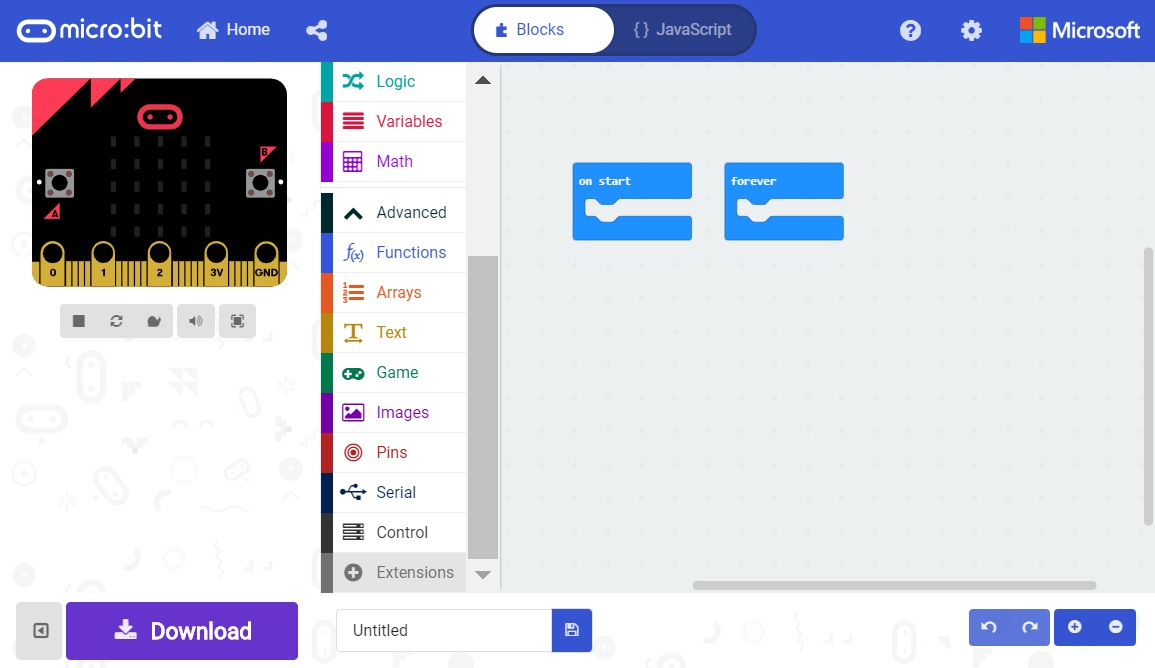
Installing a MakeCode Extension
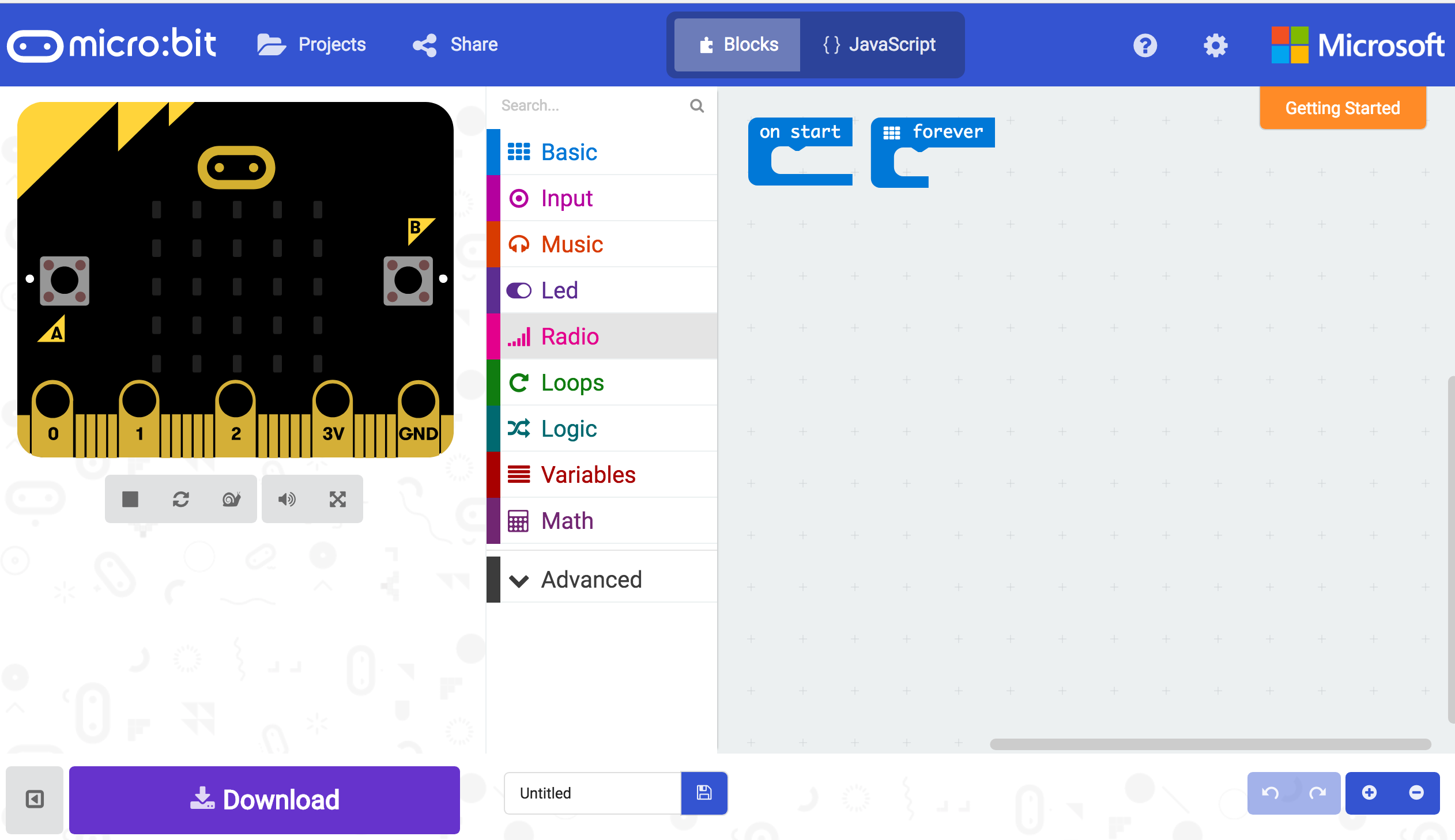
To install or add a new extension to your MakeCode toolbox (the list of different block groups), click on "Advanced" and then on "Add Extension."
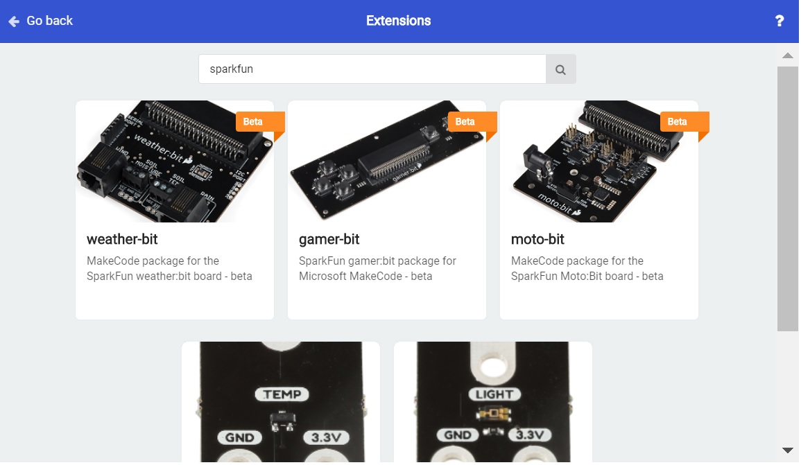
From here you can search for "SparkFun" or "SparkFun gamer-bit," and it should show up as a public extension in the list. Go ahead and click on it.
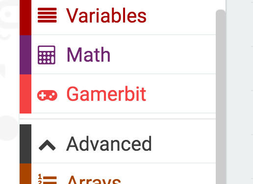
This will add all of the blocks to your toolbox. In general, this is a bit tricky as, depending on how the extension was written, it may either have its own toolbox or just add blocks to the existing ones. Take a look at your toolbox; for the gamer:bit you should see...
Great! You have now installed the gamer:bit extension and are ready to use the board as well as the components that come in the micro:arcade kit. As a side note, for every new MakeCode project that you make, you will have to load extensions over again. Not a big deal, but noteworthy! Now, let's put your extension to good use and get your game on!!!
Experiment 1: Basic Use of The Controller:bit
Introduction
We take buttons for granted! We press the keyboard in front us all day long, we use game controllers until they ware out and we never really think about what goes on behind the scenes in terms of programming or even in the hardware circuit. In this initial experiment, you will hookup your micro:bit to the controller:bit and test the buttons to make sure everything is up and running and your first introduction to the game command blocks in Microsoft MakeCode.
Parts Needed
You will need the following parts:
- 1x micro:bit Board (Not Included with Kit)
- 1x micro-B USB Cable (Not Included with Kit)
- 1x controller:bit Carrier Board
Didn't get the kit? Have no fear! Here are the parts you will need to complete this experiment. You may not need everything though depending on what you have. Add it to your cart, read through the guide, and adjust the cart as necessary.

micro:bit Board
DEV-14208Suggested Reading
- Getting Started with the micro:bit - Basic hookup and programming of the micro:bit
Introduction to the button
Buttons are part of our everyday lives! They are an actuator that closes, or completes a circuit when you press it and sometimes release it.
The buttons on the controller:bit are called momentary push buttons, meaning that they are only actuated or complete the circuit when you are physically pressing them. These types of buttons are great for things that you want to happen quickly, for example trigger a character to jump or chime in during a game show. The image below highlights one of the buttons that we will be using in this experiment.
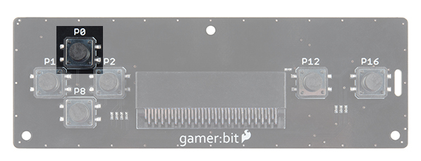
Behind the button itself you also need to realize that a button is read by a pin on your micro:bit. That pin reads whether it is HIGH or LOW, ON or OFF, 1 or 0. A pin being pulled HIGH is 3.3 volts being applied to it, while LOW is 0 volts, or grounded. A button actuation can either pull the pin HIGH or LOW depending on how it is wired as well as the program running on your micro:bit.
Hardware Hookup
The only hardware hookup at this point is inserting your micro:bit into the controller:bit correctly! Insert your micro:bit with the LED array facing up (the same direction as all of the buttons).
Running Your Script
We are going to use Microsoft MakeCode to program the micro:bit. Please open a browser window and navigate to makecode.microbit.org. This should open the makeCode environment that you used to install the gamer:bit extension in.
Be sure to add the gamer:bit extension as instructed in the Installing the gamer:bit Extension in MakeCode section of this tutorial.
Now, you can either download the following example script below and drag and drop it onto your micro:bit, or use it as an example and build it from scratch in Microsoft MakeCode.
Code to Note
Let’s take a look at the code blocks in this experiment.
Create Sprite at
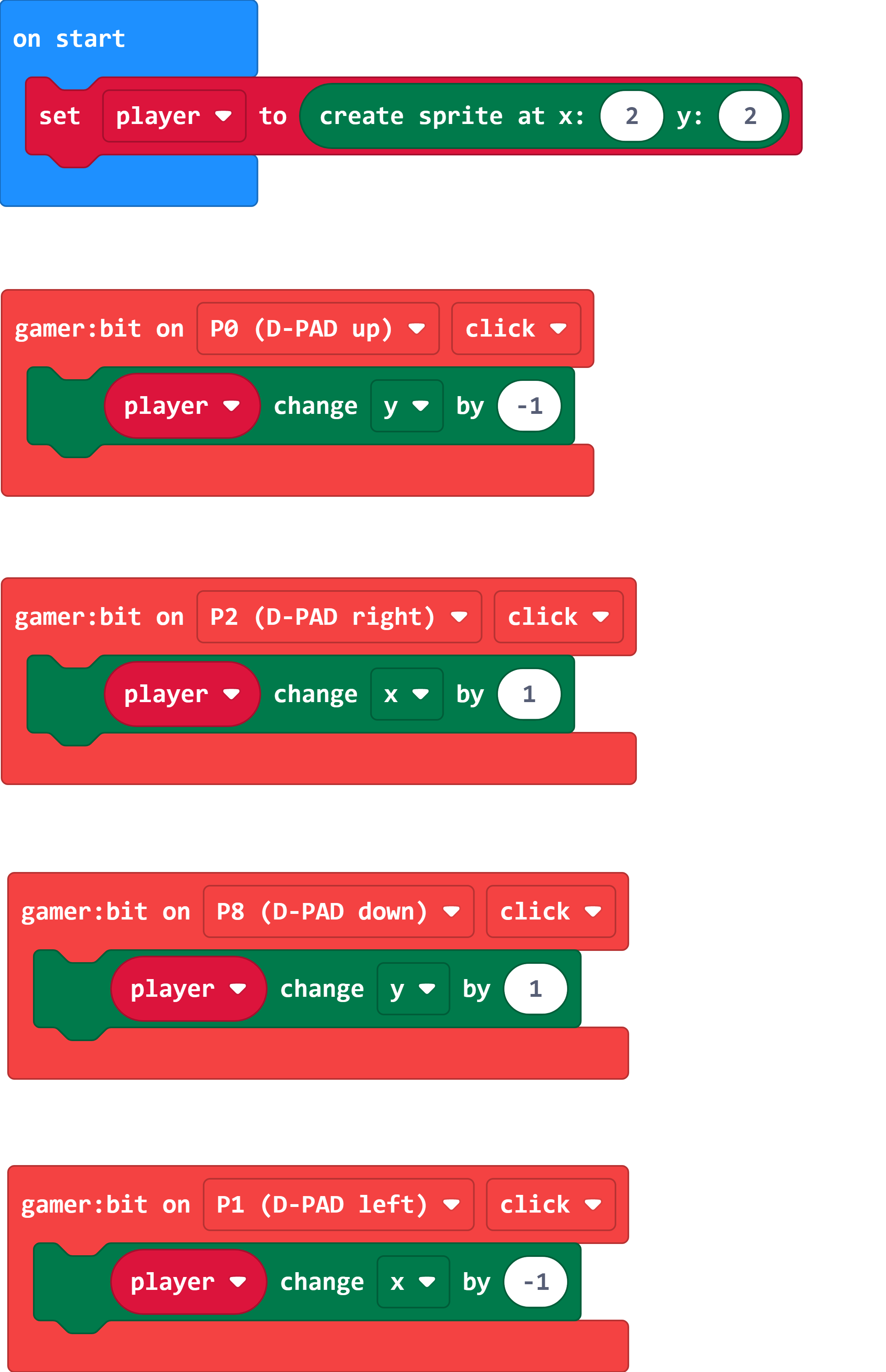
The "players" or "objects" in a video game are called sprites. On the micro:bit, sprites are a single LED in the LED array that you can control. You create a sprite by creating a variable in MakeCode.
You can create a variable under the Variables drawer and use the "Make a Variable" option and name it. We named our variable player. To initially create our sprite in the On Start block, we set the variable to Create Sprite at block and pass it an x and y value.
The coordinate system of the micro:bit's LED array starts at the top left of the array. The variable for x increases as you move from left to right (from 0 to 4). The variable fory increase from the top to the bottom (from 0 to 4). We set our sprite to the location 2,2 which is the center of the LED array.
Controller:bit On
To move our sprite around the tiny screen, we read if the D-Pad (direction buttons) are being clicked (i.e. pressed and then released) or not. We track these button clicks using an event block from the gamer:bit toobox drawer that is only triggered when you interact with a specific button on the controller:bit,. This block is called the Gamer:bit On block. You can track any of the buttons / pins on the gamer:bit as well as using following event types:
- DOWN - If the specified button is UP or being held down
- UP - If the specified button is UP or when it is released
- CLICKED - If the specified button has been pressed AND released.
[SPRITE] Change by
Under the game:bit toobox drawer, there are a number of blocks to help you manipulate or change your sprite. A basic one to start out with is the [SPRITE] Change by block. This block allows you to change x, y, direction, brightness, or blink of a sprite by a number. We use this block to change the X and Y coordinates and move the sprite around.
If we change the Y coordinate of the sprite by -1 it will move up one spot. A positive 1 will move the sprite down. For the X coordinate, positive 1 is moving to the right and -1 is to the left.
What You Should See
Once your code is loaded, you should press the direction buttons on the D-pad. As a result, your sprite should move around the screen. Pretty sweet! You have built something that is a pretty good start to a possible game.
Troubleshooting
controller:Bit blocks not showing up - Make sure you have a network connection and you have added the extension to your MakeCode environment.
micro:bit not showing up on my machine - Try unplugging the USB cable and plugging it back in. Also, be sure that you have the cable inserted all the way into your micro:bit
Button events don't seem right?! - Make sure that you have specified the correct direction to the correct direction of the X and Y coordinates.
Experiment 2: Button Reaction Timer
Introduction
You learned about reading button presses in Experiment 1 and event blocks. But, there is a bit of a problem with reading buttons that way... Events cannot be used as a variable in a simple way (similar to just reading a pin on its own). If for some reason you want to be able to read a combination of blocks at one time, or in this case use the state of a button with some other type of logic you actually need to use the Button variables that come with the gamer:bit extension. You will be building a reaction timer to test how sharp your wits really are!
We will also be adding an external button to controller:bit to give it a bit of an arcade feel!
Parts Needed
You will need the following parts:
- 1x micro:bit Board (Not Included with Kit)
- 1x micro-B USB Cable (Not Included with Kit)
- 1x controller:bit carrier board
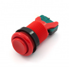
- 1x Arcade Button
- 2x Spade Wire Connectors
Didn't get the kit? Have no fear! Here are the parts you will need to complete this experiment. You may not need everything though depending on what you have. Add it to your cart, read through the guide, and adjust the cart as necessary.
micro:bit Board
DEV-14208Suggested Tools
- Ball point pen
- Hobby knife or scissors
Suggested Reading
- Getting Started with the micro:bit - Basic hookup and programming of the micro:bit
Introduction to the Arcade Buttons
The classic arcade button! Oh how we love them.

The arcade buttons work two ways as either a normally closed (NC) switch or as a normally open (NO) switch. That is to say that you can pick whether pressing the button completes, or closes the circuit. Or, breaks the circuit from a closed, or "on" state.
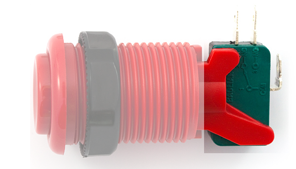
The back of each button has a the actual switch with 3 tabs. One is common or "COM" which you will always use and then either "NO" or "NC". In this case, we will be using Normally Open, but there are times where you could use Normal Closed as well.
Hardware Hookup
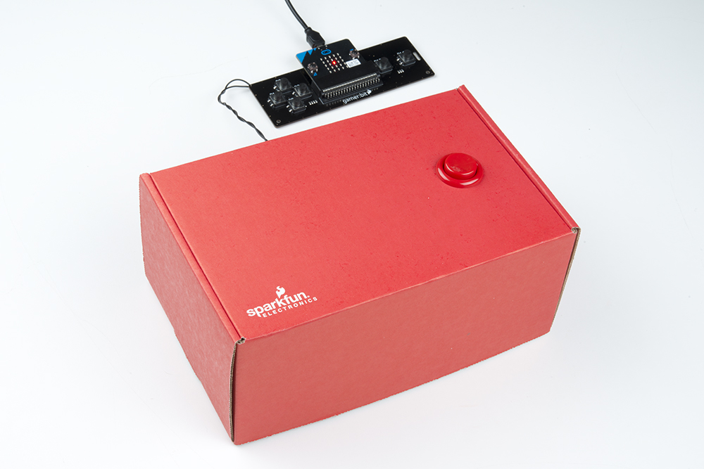
You will be hooking up one of the arcade buttons to the UP direction pad. You can then mount the button in a cardboard box or any other panel you like. The cardboard box that the kit came in is a good stand in for now!!
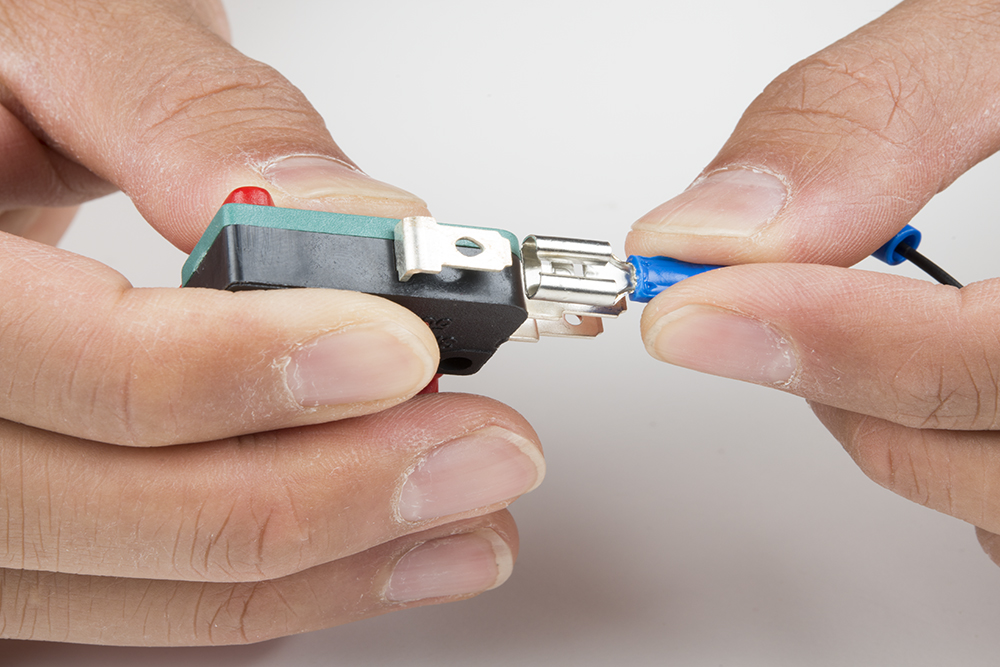
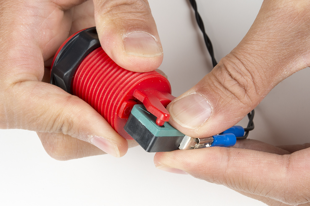
We will start out by adding the disconnect wires to the button. Start by connecting one wire to the Common (COM) pin on the button. The disconnects should slide over the tabs on the buttons snugly.
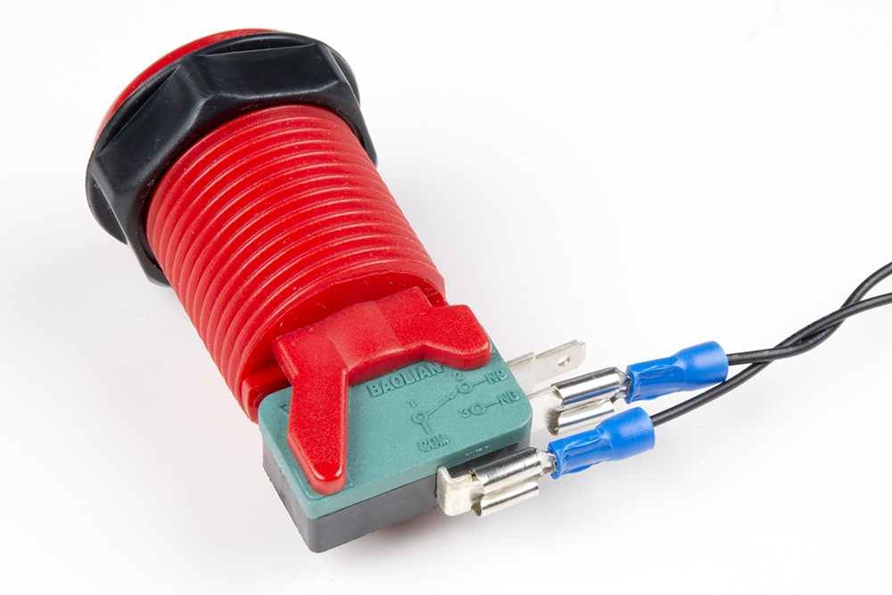
Next, for each button add another wire to the "NO" tab, on the button, you should have two wires connected to it at this point.
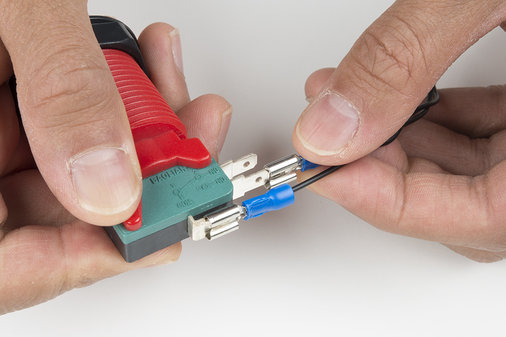
The image below shows the quick disconnects added to the terminals of the microswitch.
Finally, connect each set of wires to its corresponding poke-home connector by pressing down on the tab of the connector with a ballpoint pen and inserting the bare wire end. It doesn't matter what wire goes where in this wiring configuration as long as each wire is connected to pin P0 and P1.
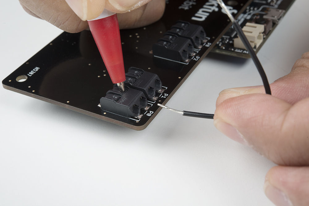
As the poke-home connector is being pressed down, insert the wire into the connector as shown below.
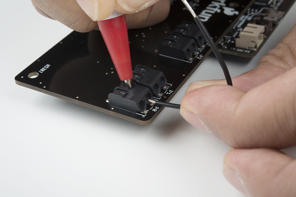
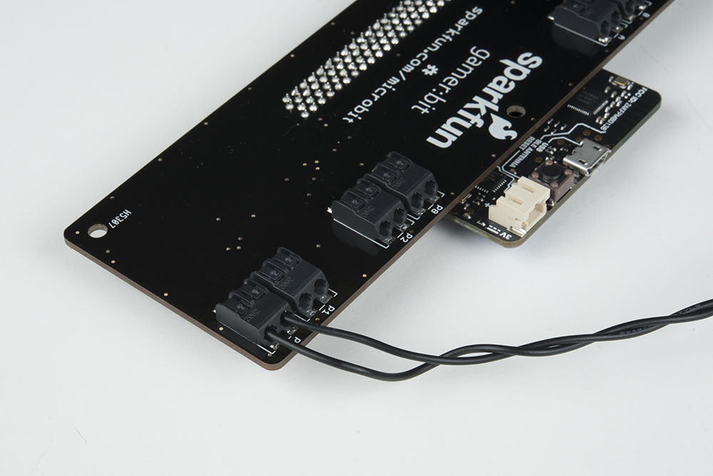
Once the wire has been inserted sufficiently into the poke-home connector, pressure from the ballpoint pen on the tab may be removed. The connector will actually hold it tight until you want to remove it. Below shows an image of the wires connected to P0 and P1.
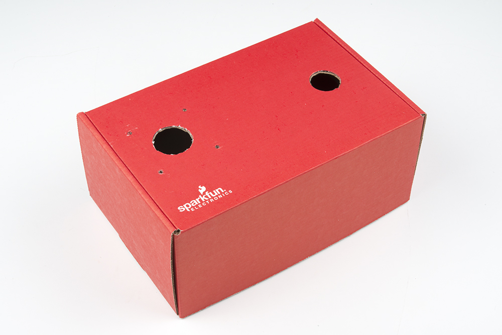
The buttons themselves are designed to be mounted to a panel made of plywood, plastic, or even through a piece of cardboard. For this project we used the box that the kit came in as a great cabinet for your reaction timer.
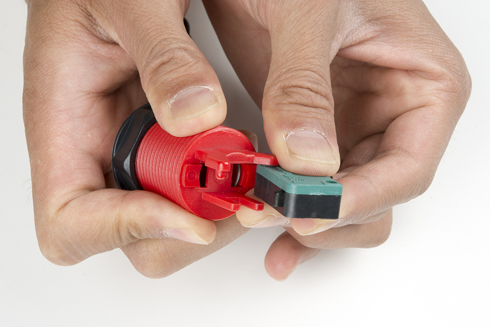
To start, we need to remove the microswitch from the bottom of the button by carefully prying it out of the mounting bracket. This isn't held in place with any hardware, just molded plastic, so be careful not to break anything. With the green side of the microswitch facing toward you, you will need to push the one of the plastic pins holding it in place. Gently twist the microswitch counterclockwise with your left hand while holding the concave button with your right hand.
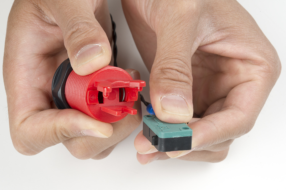
Once the plastic pins is out of one of the holes, rotate the microswitch away from the pin as shown in the image below.
Finally, slide the microswitch out by moving it out of the second molded pin.
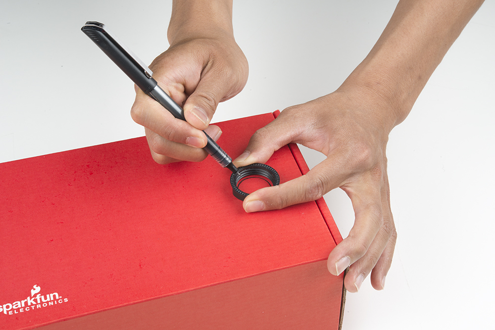
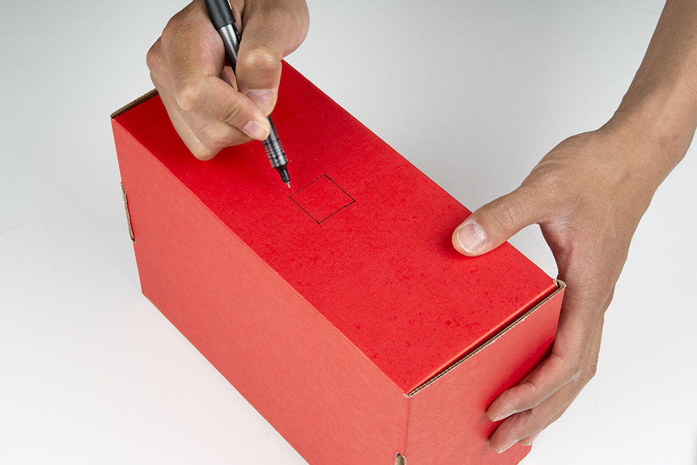
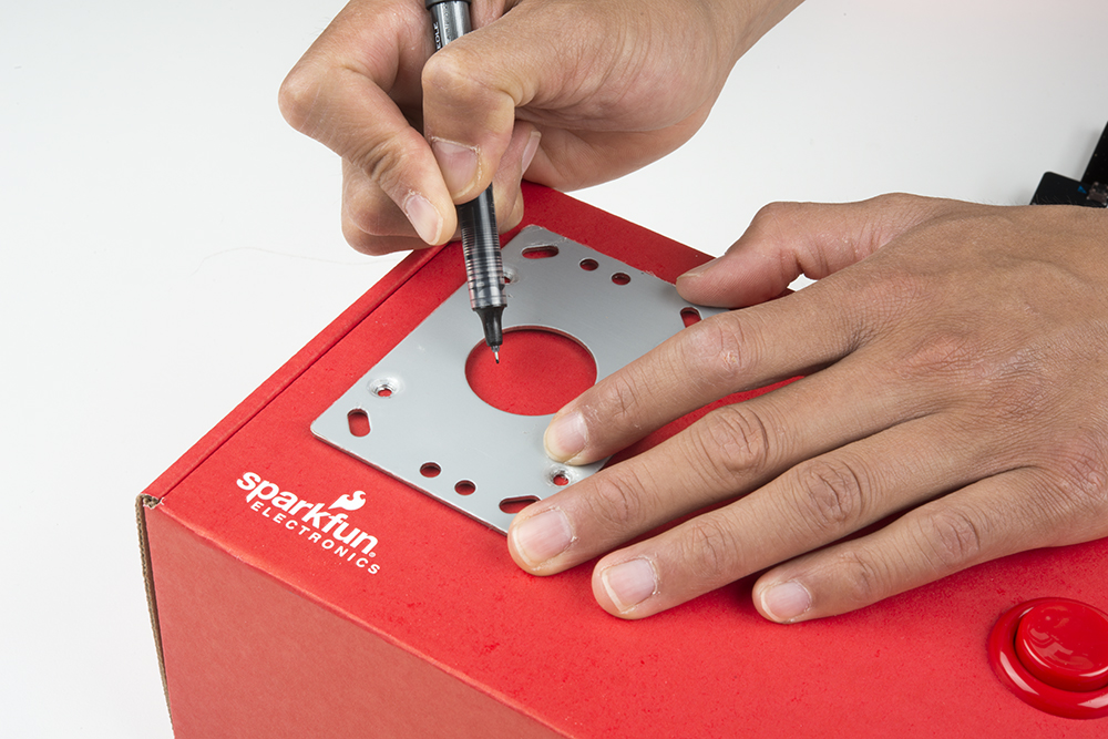
To mount the concave button, we will also need to cut a hole the cardboard box. You will need to unscrew the black ring from the concave button. In this experiment, we will be mounting the button on the top right side of the box. We can use the black ring that is attached to the concave button as a guide to cut the 1 1/8" hole. Using a pen, draw the mounting hole.
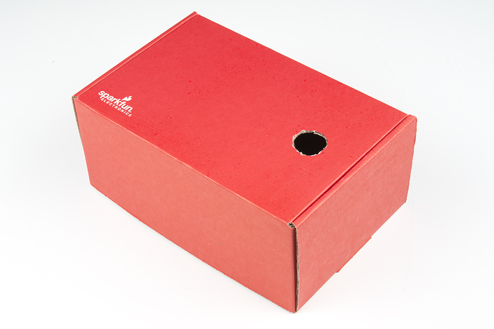
Using a craft knife or pair of scissors, cut a hole inside of the lines. Make sure to not cut too much of the cardboard box.
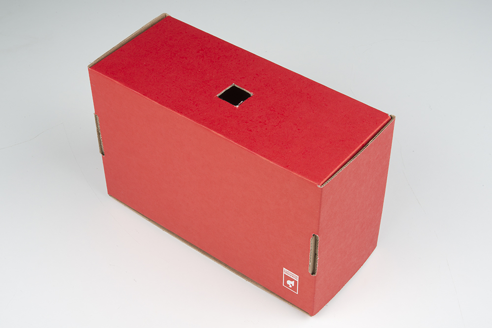
Additionally, draw about a 1" square hole on the front of the box for the wires. The square was placed in the middle for the purpose of this experiment.
Cut the square out using the craft knife or pair of scissors.
Insert the microswitch with wires through the square hole.
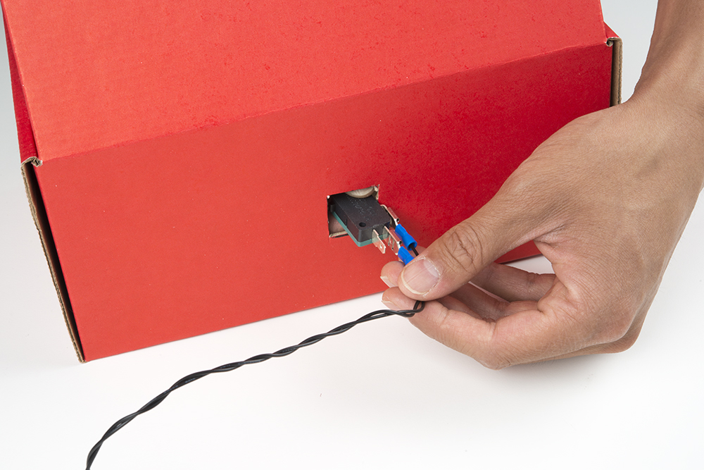
At this point, we can insert the concave button through the hole and thread the nut back onto the button from the bottom. The cardboard will be sandwiched between the concave button and the threaded nut. Finally, reattach the microswitch to the bottom of the concave button.
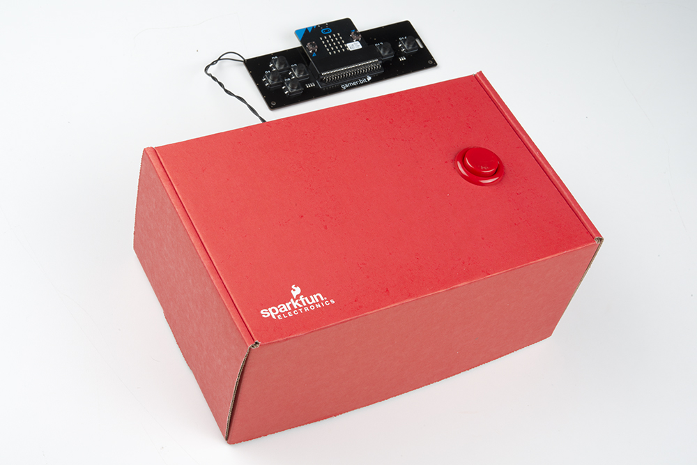
Now, give it a good mash to test it and make sure it will hold up!
Running Your Script
Now, you can either download the following example script below and drag and drop it onto your micro:bit, or use it as an example and build it from scratch in MakeCode.
Code to Note
Let’s take a look at the code blocks in this experiment.
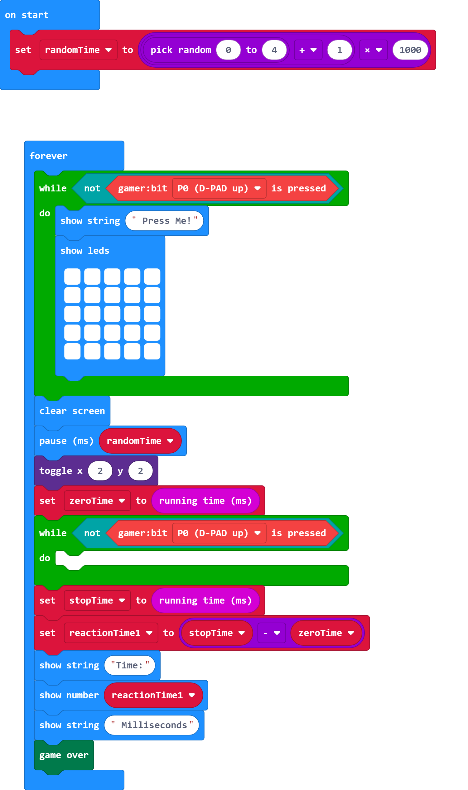
RandomTime
We create a variable called randomTime and store a value that produces a random number between 1 and 5 seconds. This will be the random time it takes that a person needs to wait before the LED will turn on so it is harder to "game" the system or cheat their reaction time.
We produce that random number using the random number to block which produces a random number between 0 and a give value, we set it to 4. To make the range between 1 and 5 seconds we added 1 and multiplied that value by 1000.
While Not Gamer:bit Pressed
Once the program starts we need it to wait until the button is pressed by the person playing. To put the program in "limbo" we use a while block that reads the opposite of the gamer:bit pressed block. In other words... while the button is NOT being pressed, the program will do nothing. We use this twice; once at the beginning to start the game and a second time to capture the reaction timing.
Toggle X Y
To turn the LED in the center of the LED array on we use the Toggle X Y block. This will toggle the LED at a given X/Y coordinate. In terms of the the LED, a "toggle" changes its state from the one that it currently is in. So toggling from OFF is to turn something ON.
ZeroTime
To keep track of a reaction time we need two values to compare; a starting point and a stopping point. We capture the staring point by creating a variable called zeroTime and setting it to running time. The running time block returns the number of milliseconds that the micro:bit has been powered up and running.
StopTime
Once the button is pressed we need to capture that current time. When the button is pressed it releases the program from the while block and captures the current time again and stores it to the stopTime variable. This is done the same way as the zeroTime variable.
ReactionTime
When we have the two different variables zeroTime and stopTime, we can calculate the player's reaction time. The reaction time is the difference between the two.
Show String / Number
We display the readout of the player's reaction time to the player once they have finally reacted. The show string block allows you to display text across the LED array. The show number block does the same thing, but for a number.
Game Over
The game over block is an animation block found under the game:bit toobox drawer of MakeCode. It does a little animation, prints out "Game Over", and then a score if you are using it.
What You Should See
Once your code is loaded to the micro:bit, you should see text scroll by that says "Push Me!". Press the button and the screen will go blank. Once the single LED lights up, press the button again as quickly as possible. Your reaction time will then be displayed followed by a game over sequence.
Troubleshooting
Game doesn't start right away - You have to wait for the text to finish scrolling by before the game starts. Make sure to press down on the button before the text finishes scrolling.
Doesn't read my button press - Make sure that you are hooked up to the correct button on the controller:bit and that all wires are securely fastened to both the button and the board.
Reads a constant button press - You have the button wired to NC (Normally closed) and so it is constantly being pressed, change the connections on the back of the button to NO (Normally Open).
Experiment 3: Fun with the Joystick
Introduction
So far we have been building and programming games that either don't have a score or require you to keep track. It is now time to pass that job off to the micro:bit. You are now going to build a simple collection game where "coins" are falling down the screen and you will control your sprite with the joystick to collect them. You will also only have 10 second before the game ends. At the end of the 10 seconds the game will be over and your score will be displayed.
Parts Needed
- 1x micro:bit Board (Not Included with Kit)
- 1x Micro-B USB Cable (Not Included with Kit)
- 1x controller:bit Carrier Board
- 1x Arcade Joystick
- 4x Spade Wire Connectors
Didn't get the kit? Have no fear! Here are the parts you will need to complete this experiment. You may not need everything though depending on what you have. Add it to your cart, read through the guide, and adjust the cart as necessary.
micro:bit Board
DEV-14208Suggested Tools
- Ball point pen
- Hobby knife or scissors
- 12" ruler
Suggested Reading
- Getting Started with the micro:bit - Basic hookup and programming of the micro:bit
Meet the Joystick
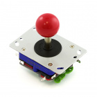
The arcade joystick is the heavy duty short handled joystick that we are all familiar with from our favorite game cabinet of our childhoods (or for most of us... yesterday).
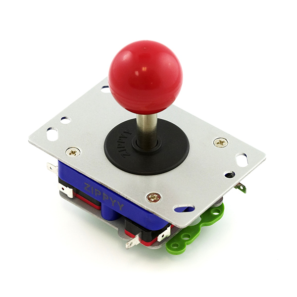
This joystick operates as four momentary push switch, one for each direction. Each switch is opposite from the directions that it controls. For example is you press the joystick "UP" the switch on the "DOWN" side of the joystick is pressed, so you have to wire it backwards to the direction the joystick is pressed.
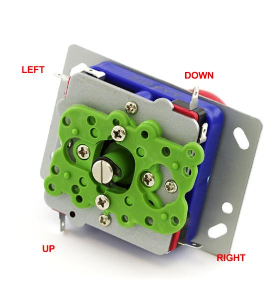
The wiring for this experiment will use the common (COM) and the Normally Open (NO) terminals on the switches.
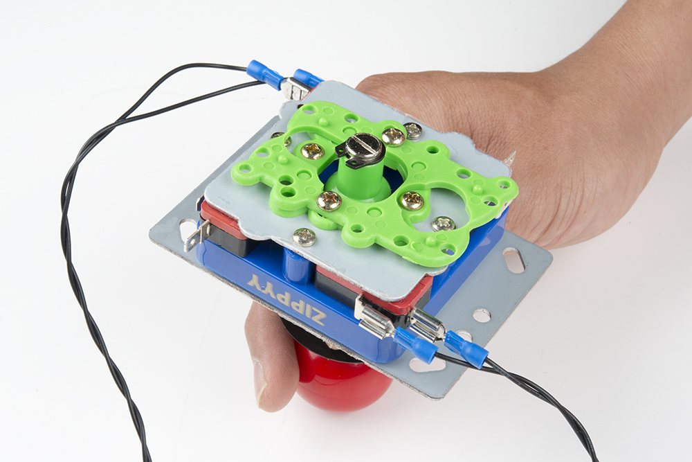
Hardware Hookup
The hardware hookup should be pretty familiar to you in a way. The Arcade joystick uses the same type of switches as the arcade buttons with the same spade connects. Hookup a spade connector wire to each switches COM and NO terminals as shown below. For this specific game you will only need the two switches that control left and right movement.
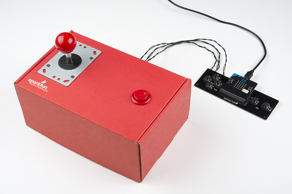
When using the joystick or the arcade buttons, it is always a great idea to mount them to a piece of cardboard or in shoe box (the box the kit comes in is the perfect size). You can mount the joystick by cutting out mounting holes for the joystick's frame.
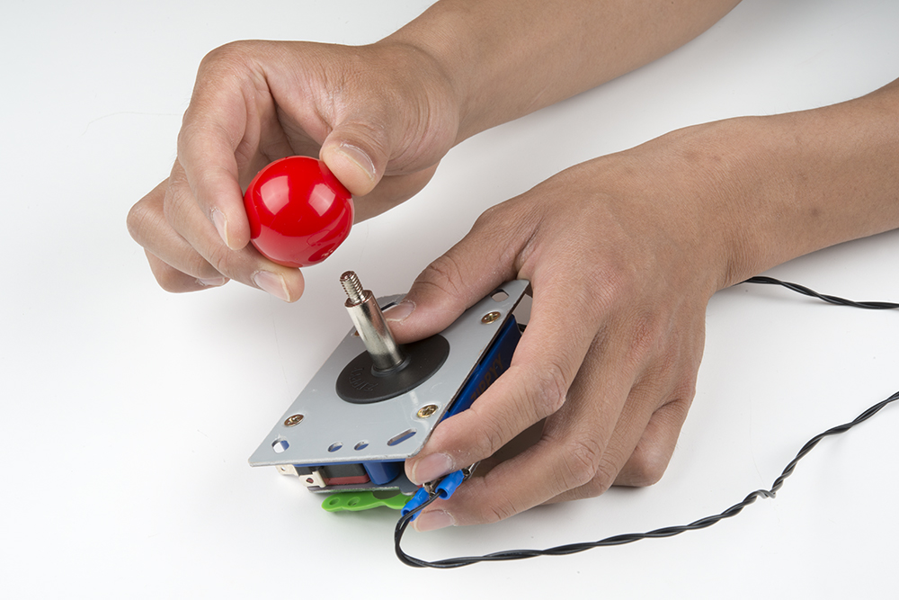
To begin, remove the knob of the joystick by unscrewing it from the shaft. This also allows you to remove the black cover ring of the joystick as well.
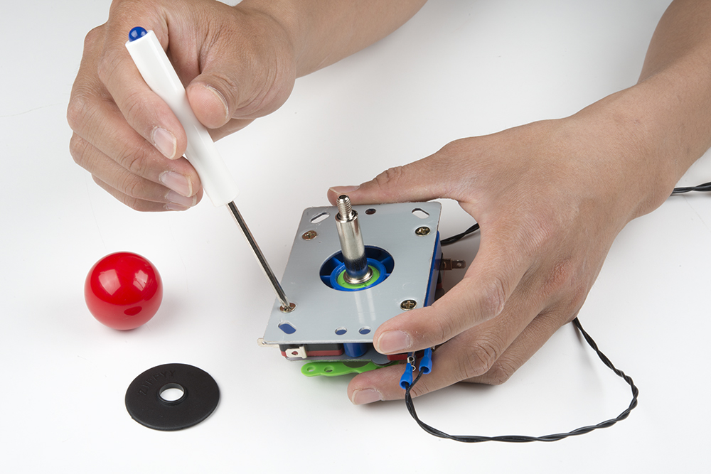
Using a Phillips head, we can remove the four screws that are holding down the frame. The SparkFun mini screwdriver was used in this experiment to remove the screws.
Once the frame has been removed, we can use it to draw the mounting holes. Place the other parts in a safe location as while cutting the cardboard box.

On the top left hand side of the box, draw the four mounting holes for the screws. Additionally, draw a hole for the shaft. Ensure that there is enough room in the enclosure to slide the spade connector into the microswitch's terminal. This would apply to the microswitch's close to the sides of the enclosure.
Using the mini screwdriver, carefully poke holes through the four mounting holes. A craft knife or pair of scissors can be used cut the hole for the shaft.
Now that the mounting holes are cut, we can attach the joystick to the cardboard box. Hold the frame against the top of the cardboard box. Attach one screw through the mounting hole using one hand. Next, pass the shaft of the joystick up through the bottom of the box until one mounting hole lines up with the screw. Twist the screw in with your hand just enough to sandwich the cardboard between the joystick and the frame. Continue adding the rest of the screws to the joystick and tighten up the scerws using the mini screwdriver.
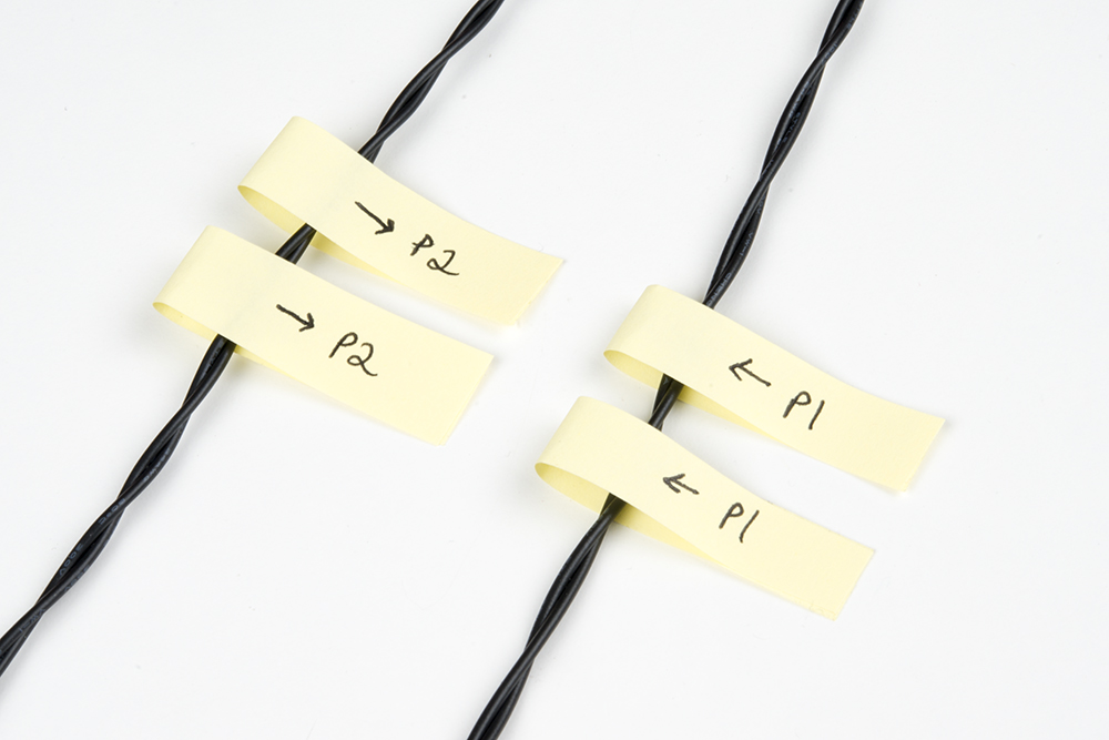
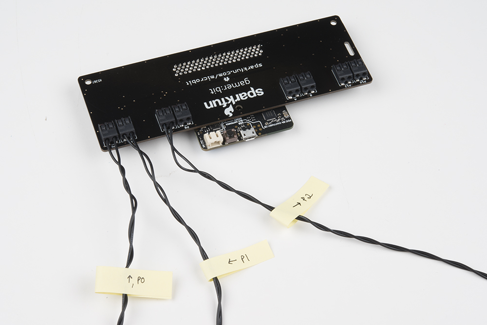
A great idea to be able to keep things straight is to label each pair of wires at the stripped ends so that when you hook it up to your controller:bit carrier board, you don't have to constantly tracing the wires back to the correct switch.
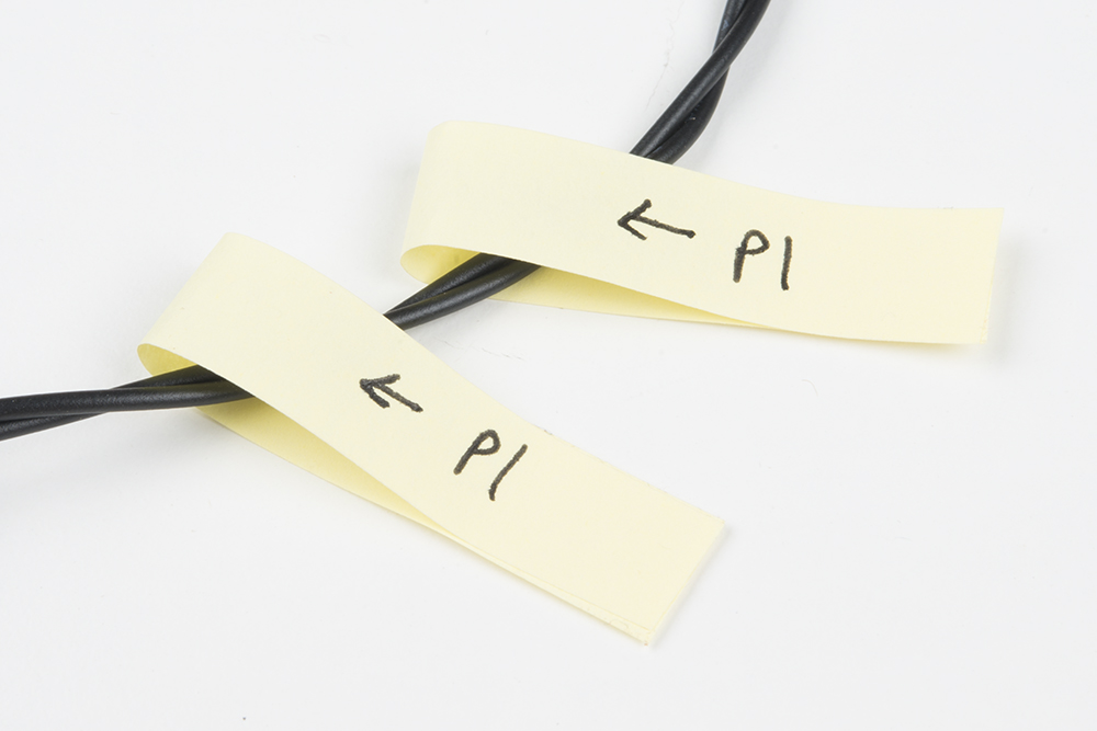
Using some sticky notes, label each wire twice for the poke-home connectors labeled P1 and P2. You can slide one label close to the joystick and the other for the controller:bit.
Hookup the stripped ends into the poke-home connectors as explained in the previous experiment by pressing down on the connector tab with a ballpoint pen, inserting the bare end of the wire into the connector, and releasing the tab. The connector will hold tight onto the wire with a snug connection. While we are at it, feel free to reconnect the concave button and label those wires.
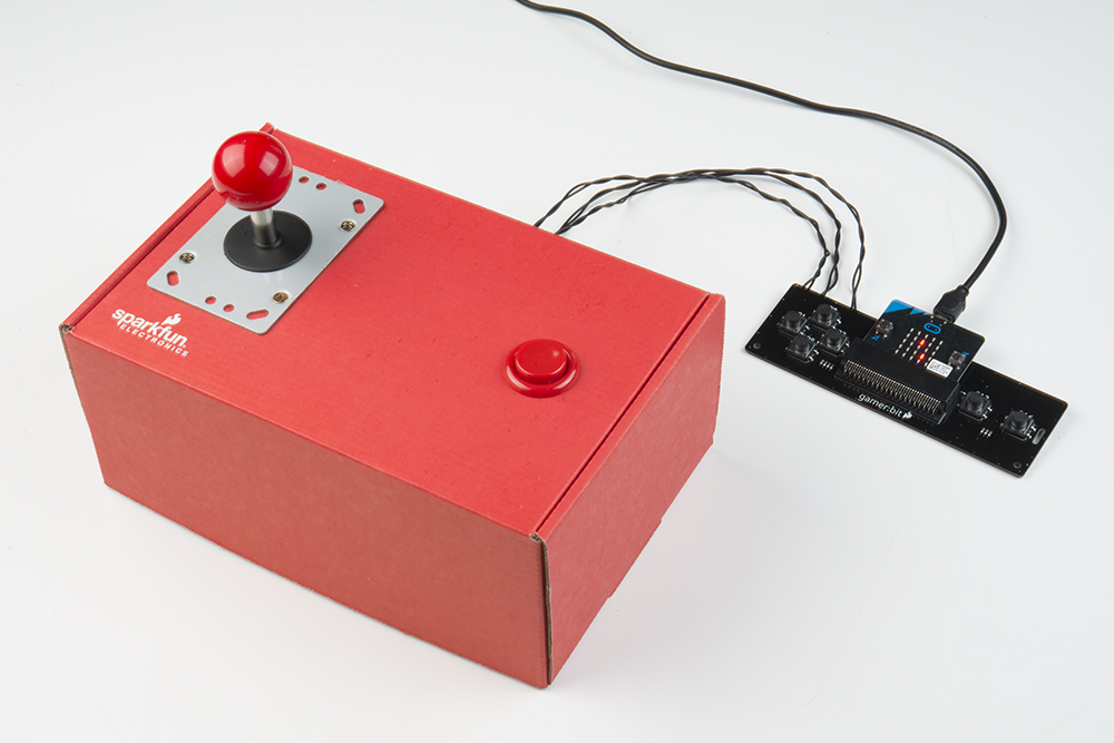
Finally, you can return the black cover ring and knob to the top of the joystick. The concave button was not used in this experiment but feel free to reattach it back to the box.

Give a quick test to make sure everything works... you should feel a nice click from the switches inside the box.
Running Your Script
You can either download the following example script below and drag and drop it onto your micro:bit, or use it as an example and build it from scratch in MakeCode.
Code to Note
Let’s take a look at the code blocks in this experiment.
Create Sprite
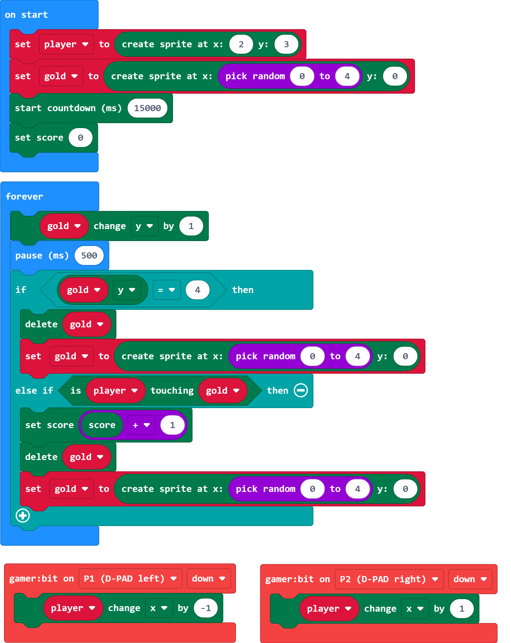
As in the previous experiments we use the Create Sprite block. This time though we use it multiple times in the program. We create our player sprite, but also a sprite for the "gold coins" that are falling that you want to capture before they go by.
Start Countdown (ms)
The start countdown block starts a timer for the length of milliseconds. At the end of that countdown, it runs a game over animation and displays the score. This simplifies this program a lot. We would have had to program that all by ourselves.
Set Score
To make sure that you are starting with a fresh game we set the score to 0 by using the Set Score block in On Start and pass it the number 0.
Change Y by
In the forever loop, we change the y value of the gold spite by 1. This creates a falling animation after the "gold" has been created in a random place along the top of the LED array.
Touching
As the "gold" falls down, we check if the "gold" sprite is touching the "player" sprite. If it is, then the player scores and the following happens.
- The player scores a point.
- The "gold" sprite is destroyed.
- A new "gold" sprite is created at the top of the LED array.
If the player misses the "gold" then it passes by the player. If the Y coordinate of the "gold" is equal to 4, then it is destroyed and and a new one is created without the player gaining a point.
Score + 1
To add to a players score, we use the set score block again, but this time in a different way. We set the score to the score variable plus 1.If you wanted to hack this project and have this subtract a point, you would change the math block from addition to subtraction.
Delete
To remove a sprite from the screen, you use the delete block that will destroy the variable storing the sprite and its information.
What You Should See
When the game starts, your sprite will show up one row above the bottom of the LED array. You control your sprite with the joystick to move left and right. "Gold" will start to fall from the top of the screen and you need to move to catch it. This will go on for 15 seconds. At the end of the 15 seconds, the game will end with the "game over" sequence and display your score. Wahoo, let's play again.
Troubleshooting
The direction of the joystick is opposite - It gets us all the time! Flip the wires around to the opposite side of the joystick from where they are are. Or, change the wires at the controller:bit.
Nothing reacts! - Double check that your controller:bit events are monitoring the correct pins that your joystick is wired to!
I can't unhook the poke-home connector - Make sure you are using a ball point pen and pressing down on the tab. Don't just pull on the wire!
Bonus Experiments!
Go further by pairing the micro:arcade kit with the micro:bot kit!
Wireless Remote Control with micro:bit
Troubleshooting the Extension
This product's extension has a dependency on Microsoft's build process. If the usual method of installing the MakeCode extension gives an error, you will need to manually install the MakeCode extension. We have provided a local build of this extension that can be uploaded to MakeCode:
To manually install this extension in makecode, go to the "Extensions" tab on the left side of the makecode site:
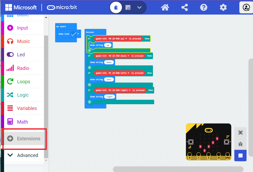
In the location you'd normally search for an extension, you'll notice an upload button on the right:
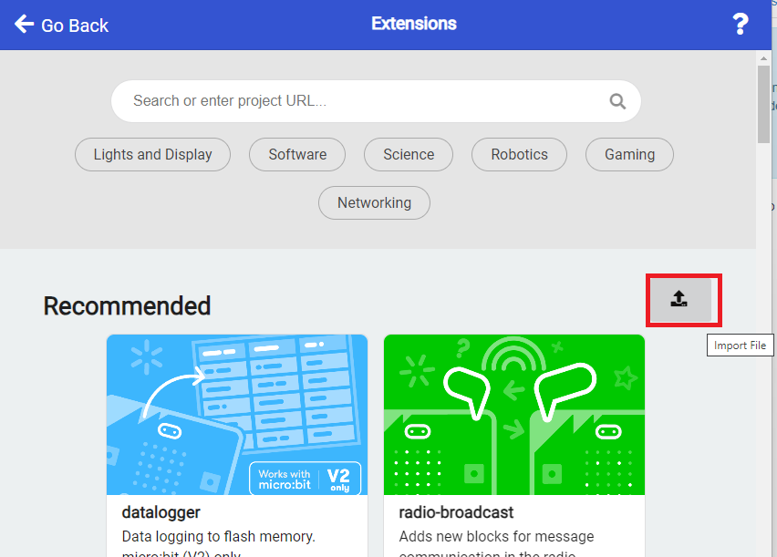
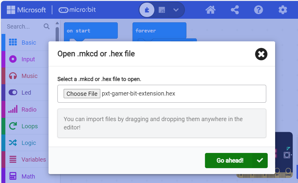
Click on this, and you'll get a window allowing you to upload your own built extension. Navigate to where you saved the above extension hex, and upload it to your project.
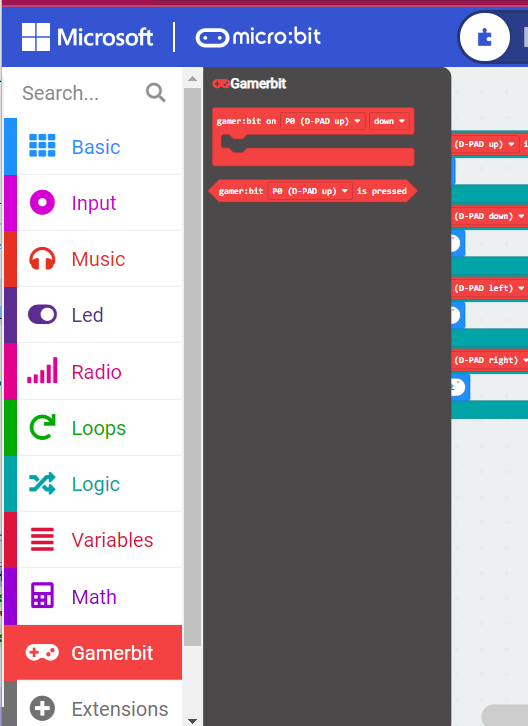
You should be able to see the extension and its functions now. In addition, you'll be able to build and download your project to your variant of micro:bit.
Resources and Going Further
For more information about the controller:bit, check out the resources below:
We produce a number of other kits and carrier boards that you can hook up to your micro:bit to help take your projects to the next level. Here is some further reading that may help you along in learning more about the world of electronics.
For more information on our micro:bit ecosystem, check out these tutorials: