micro:arcade Kit Experiment Guide
Hardware Overview
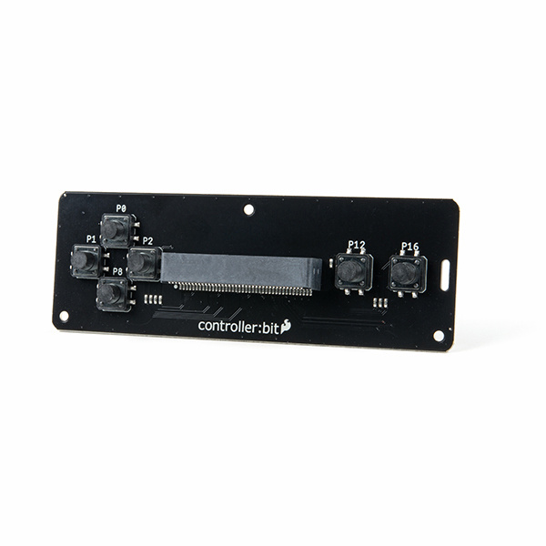
The controller:bit (formerly known as the gamer:bit) is a carrier board for the micro:bit. It is similar to an Arduino shield by adding functionality to the micro:bit without the hastle of a number of other boards, components, and all of those jumper wires connected to a breadboard.
In this case, the controller:bit takes your normal run of the mill micro:bit and turns it into a fully functional game system with a few extra parts to take your game experience to the next level. Let's take a closer look at the controller:bit!
 |
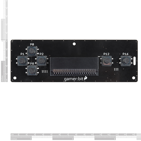 |
| Qwiic controller:bit [ DEV-16129 ] | gamer:bit [ DEV-14215 ] |
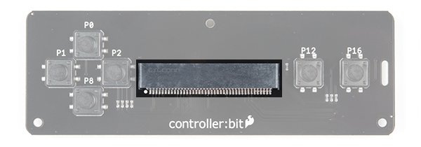
Edge Connector
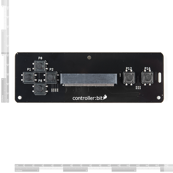
The controller:bit connects to the micro:bit via an edge pin connector in the center of the board. This makes it handy to swap out micro:bits for programming, but also gives reliable connections to all of the different pins on the micro:bit. Make sure that you insert the micro:bit correctly with the LED array facing up!
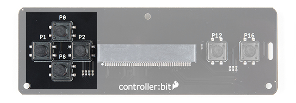
Direction Buttons
The controller:bit is designed around a classic game controller which means ther is a familiar "D Pad" style button layout on the left hand side of the board. The pins that each button controls are labeled on the board.
- UP => P0
- RIGHT => P1
- DOWN => P8
- LEFT => P2
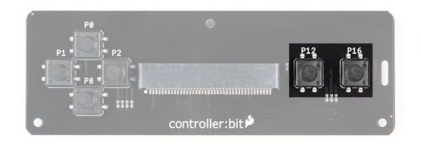
Action Buttons
There are two action buttons.
Let's name them X and Y buttons. Sorry to those used to the classic style naming, but A and B are already referenced with the buttons on the micro:bit. These buttons have no specific use other than what you program them to be. They are connected to the following pins:
- X (LEFT FUNCTION) => P12
- Y (RIGHT FUNCTION) => P16
Poke-Home Connectors
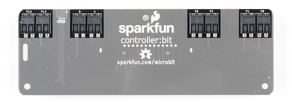
On the back of the controller:bit you will notice some odd plastic connectors. These are called poke home connectors. Each one corresponds to a button on the back of the board and are labeled as such. You will end up using these to connect your external components to controller:bits buttons. Each button has two pins to it, one for each wire to connect to the button and component.
With that, you are ready to start! Are you a user? We hope you have your chips, energy drink and eye drops because this is going to be a marathon!
Qwiic Connector
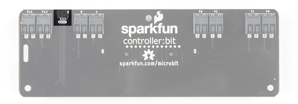
On v2.0 of the board, you'll notice the additional qwiic connector attached if you decide to connect a qwiic enabled gator device. For the scope of this tutorial, we will be focusing on the rest of the board.
Hardware Overview
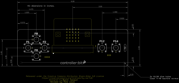
The board is about 2.00" x 6.00". THere are three mounting holes on the board if you decide to make an enclosure or secure the board to a panel.
