Gyroscope
What is a Gyroscope
Gyroscopes, or gyros, are devices that measure or maintain rotational motion. MEMS (microelectromechanical system) gyros are small, inexpensive sensors that measure angular velocity. The units of angular velocity are measured in degrees per second (°/s) or revolutions per second (RPS). Angular velocity is simply a measurement of speed of rotation.
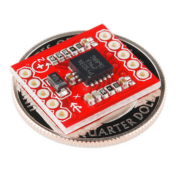
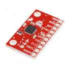
Gyros, similar to the one above, can be used to determine orientation and are found in most autonomous navigation systems. For example, if you want to balance a robot, a gyroscope can be used to measure rotation from the balanced position and send corrections to a motor. Check out a few of the ones from the SparkFun catalog.
Concepts in this tutorial
Before diving into this tutorial, you may want to read up on some of these concepts if you are unfamiliar with them.
How a Gyro Works
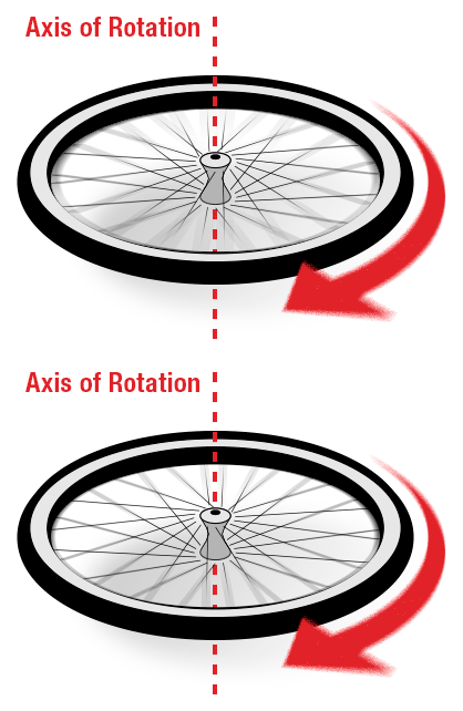
When things rotate around an axis they have what’s called angular velocity. A spinning wheel can be measured in revolutions per second (RPS) or degrees per second (°/s).
If you attach the sensor to the wheel shown above, you can measure the angular velocity of the z axis of the gyro. The other two axes would not measure any rotation.
Imagine if the wheel spins once per second. It would have an angular velocity of 360 degrees per second. The spinning direction of the wheel is also important. Is it clockwise around the axis, or is it counter-clockwise?
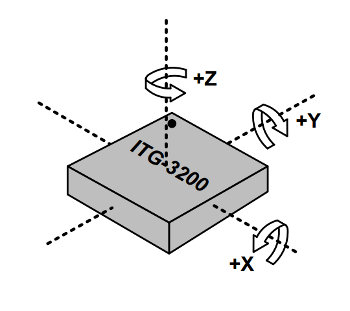
A triple axis MEMS gyroscope, similar to the one pictured above (ITG-3200), can measure rotation around three axes: x, y, and z. Some gyros come in single and dual axis varieties, but the triple axis gyro in a single chip is becoming smaller, less expensive, and more popular.
Gyros are often used on objects that are not spinning very fast at all. Aircrafts (hopefully) do not spin. Instead they rotate a few degrees on each axis. By detecting these small changes gyros help stabilize the flight of the aircraft. Also, note that the acceleration or linear velocity of the aircraft does not affect the measurement of the gyro. Gyros only measure angular velocity.
How does the MEMS gyro detect angular velocity?
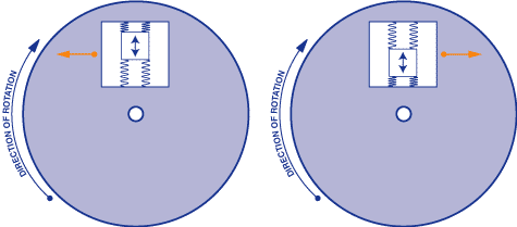
The gyroscope sensor within the MEMS is tiny (between 1 to 100 micrometers, the size of a human hair). When the gyro is rotated, a small resonating mass is shifted as the angular velocity changes. This movement is converted into very low-current electrical signals that can be amplified and read by a host microcontroller.
How to Connect to a Gyro
The primary hardware connections to use a gyro are power and a communication interface. As always, refer to the sensor datasheet for all of the information on specifications and example connections.
Communication Interface
Gyros can have either a digital or analog communication interface.
Gyros with a digital interface usually use either the SPI or I2C communication protocols. Using these interfaces allow for an easy connection to a host microcontroller. One limitation of a digital interface is max sample rate. I2C has a max sample rate of 400Hz. SPI, on the other hand, can have a much higher sample rate.
Gyros with an analog interface represent rotational velocity by a varying voltage, usually between ground and the supply voltage. An ADC on a microcontroller can be used to read the signal. Analog gyros can be less expensive and sometimes more accurate, depending on how you are reading the analog signal.
Power
MEMS gyros are generally low power devices. Operating currents are in the mA and sometimes µA range. The supply voltage for gyros is usually 5V or less. Digital gyros can have selectable logic voltages or operate at the supply voltage. For any digital interface, remember to connect 5V to 5V lines and 3.3V to 3.3V lines. Also, gyros with digital interfaces can have low power and sleep modes that allow them to be used in battery powered applications. Sometimes this is an advantage over an analog gyro.
How to Select a Gyro
There are many specifications to consider when figuring out what type of gyro to use. Here are a few of the more important useful ones:
Range
The measurement range, or full-scale range, is the maximum angular velocity that the gyro can read. Think about what you are measuring. Do you need to measure the spin of a record player, which is very slow or a spinning wheel, which could be very fast?
Sensitivity
The sensitivity is measured in mV per degree per second (mV/°/s). Don’t let the weird dimension of this value scare you. It determines how much the voltage changes for a given angular velocity. For example, if a gyro is specified with a sensitivity of 30mV/°/s and you see a 300mV change in the output, you rotated the gyro at 10 °/s.
A good rule to remember: as the sensitivity increases, the range decreases. For example, look at the LPY503 gyro datasheet or any gyro with a selectable range:
Notice that with a greater range, the sensitivity suffers and you get less resolution.
Bias
As with any sensor, the values you measure will contain some amount of error or bias. You can see gyro bias by measuring the output when the gyro is still. Though you’d think you would see 0° when the gyro is still, you will always see a slight non-zero error in the output. These errors are sometimes called bias drift or bias instability. The temperature of the sensor greatly affects the bias. To help minimize the source of this error, most gyros have a built in temperature sensor. Thus, you are able to read the temperature of the sensor and correct or any temperature dependent changes. In order to correct for these errors, the gyro must be calibrated. This is usually done by keeping the gyro still and zeroing all of the readings in your code.
Going Further
By now you should know how a gyro works and have a good foundation to start working with a gyro in a project of your own.
Check out these tutorials that use gyros:
