SparkFun Inventor's Kit for Edison Experiment Guide
 Shawn Hymel
Building the Block Stack
Before we can use the Edison in any of our circuits, we must first attach it to the Blocks in the kit. The Blocks stack in a particular order to work best with the kit.
Parts needed
You will need the following parts:
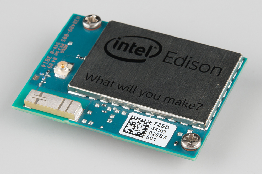
- 1x Intel® Edison
- 1x ADC Block
- 1x Base Block
- 1x GPIO Block
- 1x Edison Hardware Pack
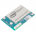
Intel® Edison
DEV-13024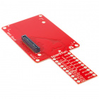
SparkFun Block for Intel® Edison - GPIO
DEV-13038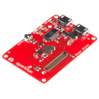
SparkFun Block for Intel® Edison - Base
DEV-13045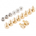
Intel® Edison Hardware Pack
COM-13187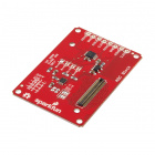
SparkFun Block for Intel Edison - ADC
DEV-13770Attach the Edison to the ADC Block
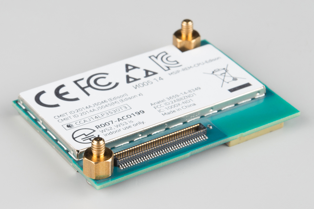
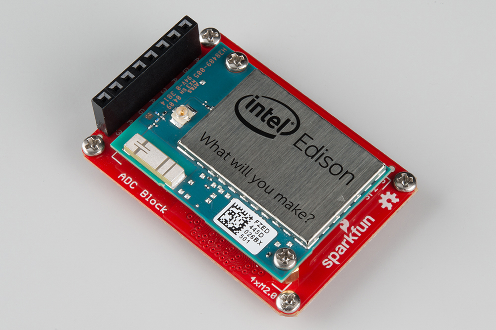
Open the Edison Hardware Pack. Put 2 screws through the mounting holes in the Edison, such that the screws' heads are facing up (we'll call "up" the surface of the Edison with the "Intel® Edison" logo).
Attach 2 standoffs to the screws sticking out the bottom of the Edison. Use the pocket screwdriver to carefully tighten the screws.
Snap the Edison into the socket on the ADC Block. Make sure that the bottoms of the standoffs are protruding through the mounting holes on the ADC Block.
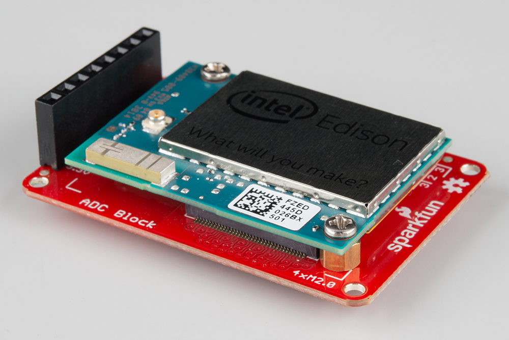
Screw 2 nuts onto the standoffs, securing the Edison to the ADC Block. You can use the pocket screwdriver to hold the screws in place while you tighten the nuts. Go slowly! The nuts can be tightened by hand, but it requires some finesse as they are quite small.

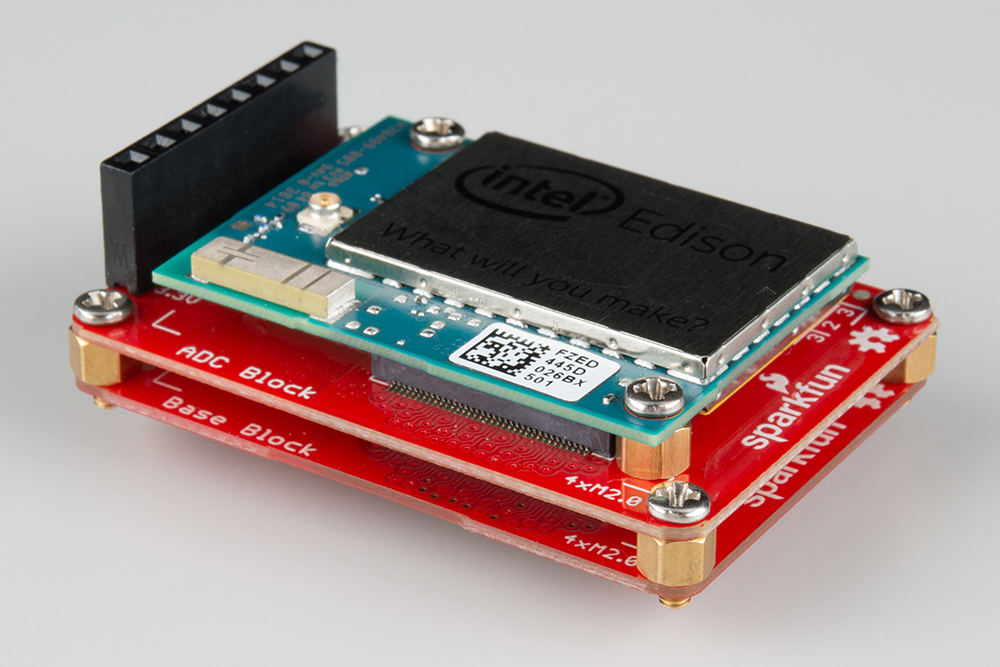
Attach the Base Block
Put 4 screws through the mounting holes on the corners of the ADC Block, such that the screws' heads are facing up (the same direction as the screws securing the Edison).
Attach 4 standoffs to those screws. Use the pocket screwdriver to carefully tighten the screws.

Snap the ADC Block (which has the Edison on top) into the socket on the Base Block. Make sure that the bottoms of the standoffs are protruding through the mounting holes on the Base Block.
Attach the GPIO Block
Attach 4 standoffs to the bottoms of the standoffs that are protruding from the mounting holes on the Base Block.

Snap the Base Block (which has the ADC and Edison mounted on top) into the socket on the GPIO Block. Make sure that the bottoms of the standoffs are protruding through the mounting holes on the GPIO Block.
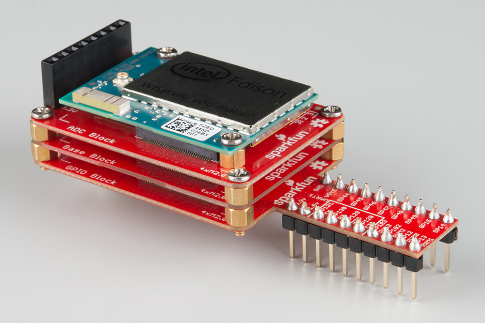
Screw the remaining 4 nuts onto the standoffs, securing the entire stack of Blocks together.
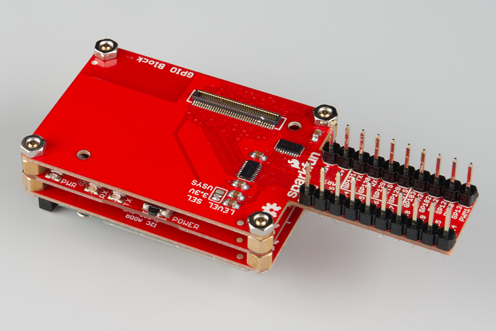
Flip the entire stack around, and make sure it is in the following order:
- Edison
- ADC Block
- Base Block
- GPIO Block
