Experiment Guide for the Johnny-Five Inventor's Kit
 rwaldron,
  reconbot,
  D___Run___,
  lyzadanger,
  Shawn Hymel
 Experiment 1: Blink an LED
Introduction
Making an LED (Light-Emitting Diode) blink is the most basic "Hello, World!" exercise for hardware, and is a great way to familiarize yourself with a new platform. In this experiment, you'll learn how to build a basic LED circuit and use Johnny-Five with your Tessel 2 to make the LED blink and pulse. In doing so, you'll learn about digital output and Pulse Width Modulation (PWM).
Perhaps you've controlled LEDs before by writing Arduino sketches (programs). Using Johnny-Five + Node.js to control hardware is a little different, and this article will illustrate some of those differences. If you're totally new to all of this — not to worry! You don't need any prior experience.
Preflight Check
Whoa there, Turbo! If this is your first experiment with the Johnny-Five Inventor's Kit (J5IK) and the Tessel 2, there are a few things you gotta do first:Parts Needed
You will need the following parts for this experiment:
- 1x Tessel 2 and USB cable
- 1x Breadboard
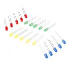
- 1x Standard LED (Choose any color in the bag full of LEDs)
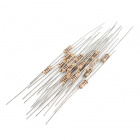
- 1x 100Ω Resistor
- 2x Jumper Wires


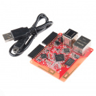
Tessel 2
DEV-13841Suggested Reading
The following tutorials provide in-depth background on some of the hardware concepts in this experiment:
- What is a Circuit? — explains what circuits are and how they work
- Voltage, Current, Resistance, and Ohm's Law — demonstrates the vital relationships between voltage, current and resistance as described by Ohm's Law
- LEDs (Light-Emitting Diodes) — the details on how those ubiquitous little lights work
- Resistors -- Why use resistors? Learn more about resistors and why they are important in circuits like the ones in this tutorial
- Polarity -- Polarity is an important characteristic to pay attention to when building circuits
Introducing LEDs
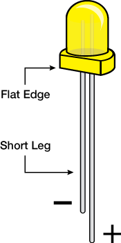
Diodes are electronic components that only allow current to flow through them in a single direction, like a one-way street. Light-Emitting Diodes (LEDs) are a kind of diode that emit light when current flows through them.
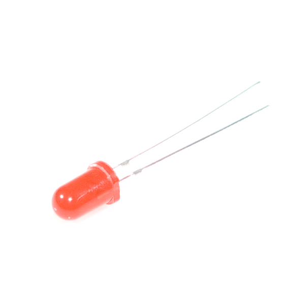
Grab an LED and take a look at it. The longer leg is called the anode. That's where current enters the LED. The anode is the positive pin and should always be connected to current source. The shorter leg, the cathode, is where current exits the LED. The cathode is the negative pin and should always be connected to a pathway to ground. Many LEDs also have a flat spot on the cathode (negative) side.
If you apply too much current to an LED, it can burn out. We need to limit the amount of current that passes through the LED. To do that, we'll use a resistor. When you use a resistor in this way to limit current, it is called — surprise! — a current-limiting resistor. With the Tessel 2 board, you should use a 100 Ohm resistor. We have included a baggy of them in the kit just for this reason!
If you're curious to learn more about how voltage, current and resistance relate to one another, read this tutorial about Ohm's Law.
Hardware Hookup
Its now the fun part! It's time to start building your circuit. Let's take a look at what goes into building this circuit.
| Polarized Components | Pay special attention to the component’s markings indicating how to place it on the breadboard. Polarized components can only be connected to a circuit in one direction. |
Polarity
LEDs are polarized, meaning they need to be oriented in a specific direction when they are plugged in. You don't want to plug a polarized part in backward!
On the other hand, resistors are not polarized; they're symmetric, which means they don't have an opinion about which way current flows across them. You can plug a resistor in facing either direction in a circuit, and it will be just fine.
Plugging Things In
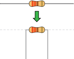
When working with components like resistors, you'll need to bend their legs at (about) 90° in order to correctly fit into the breadboard sockets. You can trim the legs shorter to make them easier to work with, if you like:
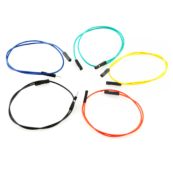
All jumper wires work the same. They are used to connect two points together. All of the experiments in this guide will show the wires with different colored insulations for clarity, but using different combinations of colors is completely acceptable.
Breadboards are vital tools for prototyping circuits. Inside the breadboard there are electrical connections between certain sockets. Power rails — columns on the left and the right of the breadboard — are electrically connected vertically, while terminal rows — rows in the middle of the breadboard — are connected horizontally (note that connections do not continue across the center notch in the breadboard).

You can read a tutorial about breadboards to learn more.
Build the LED Circuit
Each of the experiments in this guide will have a wiring diagram. They'll show you where to plug in components and how to connect them to your Tessel 2.

- Plug the LED into the breadboard, taking care to plug the cathode into row 1 and the anode into row 2. Make sure not to plug it in backward!
- Connect a 100Ω resistor between the LED's cathode and ground as shown, spanning the notch in the middle of the breadboard.
- Use jumper wires to connect the breadboard's components to the Tessel 2: connect ground (row 1) to the Tessel 2's Port A GND pin and source (row 2) to the Tessel 2's Port A, Pin 5.
Using Johnny-Five to Make an LED Blink
Open your favorite code editor, create a file called led.js and save it in the j5ik/ directory. Type — or copy and paste — the following JavaScript code into your led.js file:
language:javascript
var Tessel = require("tessel-io");
var five = require("johnny-five");

var board = new five.Board({
  io: new Tessel()
});

board.on("ready", () => {
  var led = new five.Led("a5");
  led.blink(500);
});
Now for the big reveal! Type — or copy and paste — the following into your terminal:
t2 run led.js
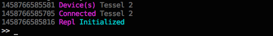
You terminal will display something like this:
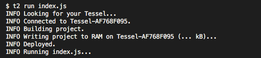
And when the program starts up:
What You Should See
Your LED should be blinking:
| State | Time |
|---|---|
| On | 500ms |
| Off | 500ms |
Exploring the Code
Let's take a deeper look at what's going on in the led.js Johnny-Five code.
Requiring Modules
In Node.js, a program can use any number of code modules. Modules are independent chunks of functionality. The software functionality for Tessel and Johnny-Five is contained within modules. We need to tell Node.js to require those modules so that they are available to the program:
language:javascript
var Tessel = require("tessel-io");
var five = require("johnny-five");
Note: For Node.js to be able to find and use the modules, you need to use npm to install for the project. That happened when you set up your working environment—you used npm install to install both the tessel-io and johnny-five modules.
Instantiating Objects
Next, the code needs to instantiate (create) a new object that represents the Tessel 2 board, and assign it to a variable (board) so we can access it later:
language:javascript
var board = new five.Board({
  io: new Tessel()
});
This creates a new instance of a Johnny-Five Board.
Johnny-Five supports many kinds of development boards. The support for some boards is built right in to Johnny-Five, but others — including Tessels — rely on external plugins encapsulated in modules. That's why the code requires the tessel-io npm module. Here, we tell Johnny-Five to use a Tessel object for IO when communicating with the board.
Learn more: Working with JavaScript Objects
Listening for Events
JavaScript code statements are typically executed top to bottom, in order, until they're "done" (the program runs to completion) and nothing is left to do. One of Node.js' great powers is to allow programmers to "schedule" things to happen outside of this simple sequential-then-done flow. A program will terminate if there's nothing left to do, but there are a number of ways to give the program something to do so that it keeps running.
Because the Tessel 2 board initialization involves hardware and I/O, it takes a few moments—considerably longer than the rest of the led.js script would take to execute. The initialization of the board won't get in our program's way—it happens asynchronously, allowing our script to keep executing statements without blocking—but we need to schedule something to happen when the board is ultimately ready.
language:javascript
board.on("ready", function() {
  // ...this will execute when the board emits the `ready` event
});
The code snippet defines a function that will get executed when ('on') the board emits the ready event.
Next we need to fill in what that function should do when the board is ready to go.
Learn more: In-depth: JavaScript's Concurrency Model and Event Loop
Blinking the LED
Once the board is ready, it's time to configure an LED on Port A, Pin 5 and then tell that LED to blink. In Johnny-Five, that looks like this:
language:javascript
board.on("ready", function() {
  var led = new five.Led("a5");
  led.blink(500);
});
Instances of Johnny-Five's Led class have some handy tools (attributes and methods) for doing LED things—for example, blink..
This code creates a new Led object and tells it what pin to use (in this case "a5"). Then it tells the LED to blink every 500 milliseconds (half a second). That means the LED will cycle 500ms off, then 500ms on.
Comparing Node.js + Johnny-Five With Arduino Sketches
The structure of Node.js scripts written with Johnny-Five differs from how Arduino sketches are written in the Arduino Programming Language. The following is an example sketch in the Arduino Programming Language that would make an LED blink on and off (assuming that LED was connected to pin 13 of a theoretical board):
language:cpp
void setup() {
  pinMode(13, OUTPUT); // Set up pin 13 as an OUTPUT pin
}

void loop() {
  digitalWrite(13, HIGH);   // turn the LED on (HIGH puts voltage on the pin)
  delay(500);               // wait for a half second
  digitalWrite(13, LOW);    // turn the LED off by making the voltage LOW
  delay(500);               // wait for a half second
}
Arduino sketches have two sections:
setup: runs once and is a place for configuring pins and initializing stuffloop: runs over and over and over and over
Another thing you'll notice is that Arduino code is lower-level, meaning that there are fewer abstractions of specific hardware details. Instead of having an LED object that can do LED-like things (blink, pulse, fade, etc.), you interact directly with the digital pin and write LOW and HIGH states to it.
Between those digital writes, you tell everything to stop and wait for 500 milliseconds (delay). And the thing about delay is: it stops everything. It's a process-blocking operation. Nothing else can happen while delay, well, delays.
In terms of code complexity, the difference between Johnny-Five and the Arduino Programming Language isn't too significant when you're just blinking an LED, but when it comes to pulsing an LED, Arduino sketch code starts getting more complicated.
Pulsing an LED
Now that we've covered the basics and some of the lower level technical aspects of Johnny-Five, let's write a program that pulses the LED. Instead of blinking the LED on and off, pulsing fades the LED smoothly from off to on, and then from on to off again.
Pulse Width Modulation (PWM)
The state of a digital output pin can only be one of two things: LOW or HIGH. That means, at any given exact moment, an LED connected to the pin can only be off or on. We fool the eye into thinking an LED is dimmed to, say, half brightness by using a technique called Pulse Width Modulation (PWM)
With PWM, the pin can be switched between HIGH and LOW very quickly, causing the LED turn on and off, too. This cycle between on and off happens too fast for the human eye to discern. The percentage of time that the pin (with the LED attached) is HIGH (on) over a given period is its duty cycle. A 30 percent duty cycle (on — or HIGH — 30% of the time) will make an LED look like it's partially lit — dimmer than bright but definitely on. By adjusting the duty cycle over time, we can fake (very convincingly!) an LED fading on and off.
Only certain pins on development boards support PWM. On the Tessel 2, pins 5 and 6 on both ports (A and B) support PWM.
Pulsing an LED With Arduino
Pulsing an LED in an Arduino sketch (Arduino Programming Language) requires more effort than blinking. Much has changed here from the blinking sketch, but certain things remain the same. There is still a process-blocking operation (delay), this time for 30ms on each loop cycle. We can no longer use the digitalWrite() function (it can only write binary LOW or HIGH); instead we'll need the analogWrite() function for writing PWM values from 0 (0% duty cycle) to 255 (100% duty cycle). There are also now three variables to keep track of: led for the pin number, brightness to track the present brightness state, and lastly fadeAmount which holds the increase or decrease value to be applied to the value of brightness. Whew!
Here's what that looks like all together:
language:cpp
int led = 9;           // the PWM pin the LED is attached to
int brightness = 0;    // how bright the LED is
int fadeAmount = 5;    // how many points to fade the LED by

void setup() {
  pinMode(led, OUTPUT);
}

void loop() {
  analogWrite(led, brightness);

  brightness = brightness + fadeAmount;

  if (brightness == 0 || brightness == 255) {
    fadeAmount = -fadeAmount ;
  }

  delay(30);
}
It may be hard to get your head around the logic in that program. It's not that easy to read. It doesn't scream "pulse an LED" in the way that it expresses itself, does it?
Pulsing an LED With Johnny-Five
Let's see what pulsing an LED looks like in Johnny-Five. Open your led.js script again. You'll need to edit one line. Change the line that currently reads:
led.blink(500);
to
led.pulse(500);
No kidding—that's it! No need to keep track of things, handle scheduling and timing or do arithmetic—instances of Johnny-Five's Led do it all for you. Like blink, the pulse method takes an argument that is the pulse period in milliseconds. Here is the complete script for your copying-and-pasting convenience:
language:javascript
var Tessel = require("tessel-io");
var five = require("johnny-five");

  var board = new five.Board({
    io: new Tessel()
  });

  board.on("ready", function() {
    var led = new five.Led("a5");
    led.pulse(500);
  });
Remember, to run the script and see your LED pulse, type — or copy and paste — the following command in a terminal:
t2 run led.js
What You Should See
Your LED should be pulsing in 500ms period cycles.
Building Further
Try adjusting the speed passed to the led.blink() and led.pulse() calls. For example: led.blink(1000) or led.pulse(1000) would change the cycles to 1000ms periods.
Reading Further
- JavaScript — the programming language used in these experiments
- Working with JavaScript objects
- Node.js — JavaScript runtime where your programs will be executed
- Johnny-Five — framework written in JavaScript for programming hardware interaction on devices that run Node.js
- Arduino Programming Language
- Working with JavaScript objects