Experiment Guide for the Johnny-Five Inventor's Kit
 rwaldron,
  reconbot,
  D___Run___,
  lyzadanger,
  Shawn Hymel
 Experiment 5: Reading an SPDT Switch
Introduction
You got your first taste of processing digital input in Exercise 4 by working with a push button. This experiment introduces a Single-Pole, Double-Throw (SPDT) switch. You'll see how the Johnny-Five Switch class can be used with a variety of physical switches, including a magnetic switch that you can use to protect your lunch from marauding fridge raiders. This experiment also includes the integration of a third-party module and service, Twilio, which you can use to send SMS text messages — now that's leveling up!
Preflight Check
Whoa there, Turbo! If this is your first experiment with the Johnny-Five Inventor's Kit (J5IK) and the Tessel 2, there are a few things you gotta do first:Suggested Reading
The following tutorial provides in-depth background on some of the hardware concepts in this experiment:
- Switch Basics — Types of switches, what they do, and how they work
Parts Needed
You will need the following parts for this experiment:
- 1x Tessel 2
- 1x Breadboard
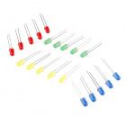
- 1x Standard LED (any color is fine)
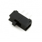
- 1x SPDT Switch
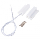
- 1x Magnetic Door Switch
- 1x 100Ω Resistor
- 7x Jumper Wires


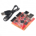
Tessel 2
DEV-13841Introducing the Single-Pole, Double-Throw (SPDT) Switch

SPDTs have three legs: one common leg and two legs that vie for connection to the common leg. The common pin is in the middle. It's always connected to one of the outside pins, but which pin it's connected to depends on which way the switch is flipped. The state of the switch — "on" or "off" — is read from the common leg. A connected digital input pin on the Tessel will read HIGH when the common leg is electrically connected to the +3.3V leg on the switch; that means the switch is "on." It will read LOW when the common pin is connected to the ground pin (switch in the "off" position).
Note: The circuit in this experiment doesn't need a pull-down or pull-up resistor like the one in Experiment 4. That's because the common pin in the switch is always connected to something. There's never a "disconnected" state that can cause floating. There's a nice tutorial about pull resistors if you'd like to learn more.
Hardware Hookup
This experiment has two wiring diagrams, but let's not get ahead of ourselves! The first is below:
| Polarized Components | Pay special attention to the component’s markings indicating how to place it on the breadboard. Polarized components can only be connected to a circuit in one direction. |
Building the Switch Circuit
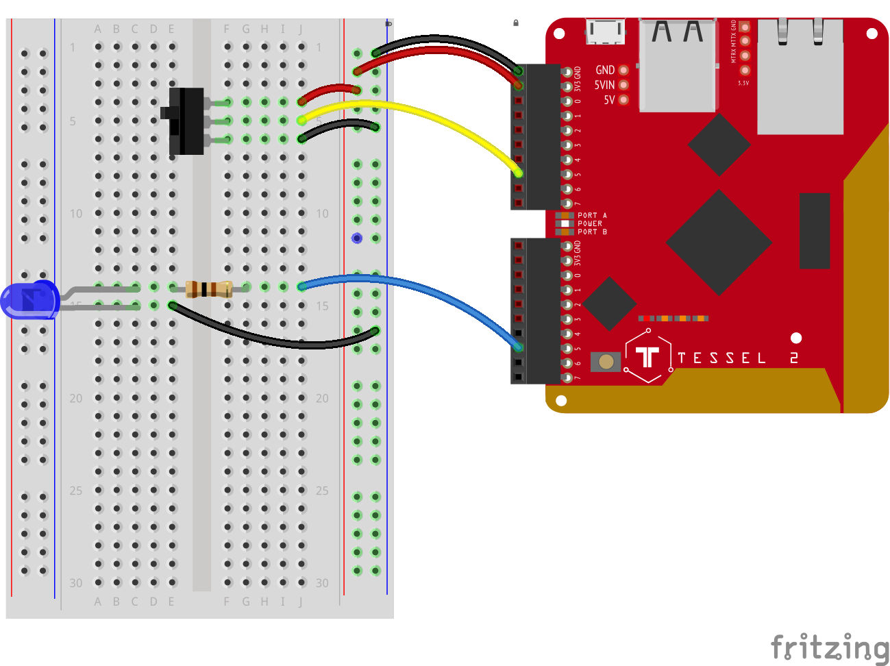
- Plug the LED in, be sure to note that the anode is towards the top of the breadboard with each leg plugged into its own row.
- Place the 100Ohm resistor so that one leg is in the same row of hole as the anode of the LED and spans the ditch plugging into the row adjacent to the LED.
- Using jumper wires connect the cathode of the LED to the ground rail of the breadboard and the a separate wire connecting the end of the resistor to Pin 5 of Port B on your Tessel.
- Insert the SPDT switch into the breadboard so that each of the 3 pins insert into their own rows.
- Using jumper wires connect the upper pin of the switch to the positive power rail, the lowest pin to the ground power rail and the center pin to Pin 5 on Port A of your Tessel. 6.Finally power the breadboard using jumper wires! connect 3.3V to the positive rail and GND to the ground rail.
Observing a Switch With Johnny-Five
Open your favorite code editor, create a file called switch.js and save it in the j5ik/ directory. Type — or copy and paste — the following JavaScript code into your switch.js file:
language:javascript
var Tessel = require("tessel-io");
var five = require("johnny-five");

var board = new five.Board({
  io: new Tessel()
});

board.on("ready", () => {
  var spdt = new five.Switch("a5");
  spdt.on("close", () => console.log("Switch closed"));
  spdt.on("open", () => console.log("Switch opened"));
});
Type — or copy and paste — the following into your terminal:
t2 run switch.js
Note: The minimum version of Node.js that runs on Tessel 2 supports many ES2015 features, including Arrow Functions, which we will be using throughout this experiment to simplify your program code.
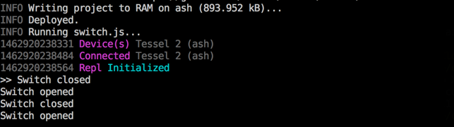
What You Should See
When you slide the switch back and forth, your terminal will display the appropriate message:
Exploring the Code
As in all previous experiments, once the board object has emitted the ready event, we can initialize an instance of the Switch class to interact with our hardware:
language:javascript
var spdt = new five.Switch("a5");
Next, create two event listeners: one for the close event (which means the switch is "on") and one for the open event (the switch is "off"). These events are conceptually very similar to the Button events that we covered in Experiment 4. Buttons are, after all, a kind of switch too.
language:javascript
spdt.on("close", () => console.log("Switch closed"));
spdt.on("open", () => console.log("Switch opened"));
And that's it! Flipping the switch back and forth will cause Switch closed and Switch opened messages to display in the console (your terminal window's output).
Variation: Using a Switch to Control an LED with Johnny-Five
As a minor modification, create a new Led object and control its on/off state with the Switch. Type — or copy and paste — the following JavaScript code into your switch.js file:
language:javascript
var Tessel = require("tessel-io");
var five = require("johnny-five");

var board = new five.Board({
  io: new Tessel()
});

board.on("ready", function() {
  var led = new five.Led("b5");
  var spdt = new five.Switch("a5");
  spdt.on("close", () => led.on());
  spdt.on("open", () => led.off());
});
Type — or copy and paste — the following into your terminal:
t2 run switch.js
What You Should See
When the switch is in one position, the LED is off. When the switch is in its other position, the LED is on.
Exploring the Code
Just as we did in all previous experiments, once the board object has emitted the ready event, we can initialize instances of the Led and Switch classes to interact with our hardware:
language:javascript
var led = new five.Led("b5");
var spdt = new five.Switch("a5");
This time, instead of logging (displaying) messages, the Switch event handlers will turn the LED on or off, depending on which state the circuit is in:
language:javascript
spdt.on("close", () => led.on());
spdt.on("open", () => led.off());
Monitoring a Fridge With Johnny-Five
Ever had a pesky coworker who has a habit of swiping your lunch? Let's try to catch her in the act! For this experiment, you're going to make a surveillance device that will send us an SMS text message when a refrigerator door is opened.
Introducing the Magnetic Door Switch
In Experiment 4 and the first example in this experiment, you built circuits containing switches controlled by direct human contact: fingers pressing or flipping. The door switch included in the Johnny-Five Inventor's Kit is a little different: it is sensitive to a magnetic field.
The switch assembly has two pieces. When the two halves of the switch assembly are very near each other, or touching, the switch is in one state. Moving the two halves more than 20mm apart from each other will cause the switch to change state. One half contains a magnet, and the other contains a reed switch, a switch that changes state when exposed to a magnetic field.
This type of two-piece switch is often used in home-security systems. One half of the switch is attached to a fixed surface, and the other half to a moving door or window. When the door or window is opened, the two halves are separated from each other, breaking the contact and changing the switch's state.
Building the Circuit
Build the magnetic switch circuit using the wiring diagram:
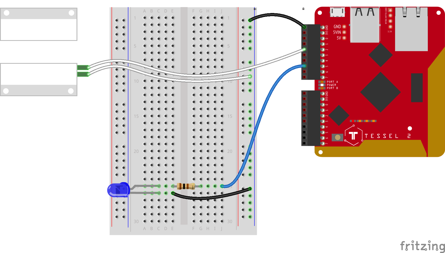
- Using jumper wires, connect one half of the switch assembly to Port A, Pin 2 and the ground column of the breadboard's power rail. It doesn't matter which pin of the switch is connected to GND or the input pin — both orientations work fine.
- Plug in the LED. Connect the anode to Port A, Pin 5 through a 100Ω resistor. Connect the cathode to the ground column of the power rail using a jumper wire.
- Connect the Tessel's GND pin to the breadboard's power rail using a jumper wire.
Building a Prototype
Before we start sending SMS messages out into the ether, let's use the circuit above to create a prototype. This will prove our hardware is set up correctly. For the moment, instead of dispatching a text message, we'll indicate the switch's status with an LED. We'll turn the LED on when the "door opens" (switch halves are separated) and shut it off when the "door closes" (switch halves are near or touching).
Open your favorite code editor, create a file called intruder-alert.js and save it in the j5ik/ directory. Type — or copy and paste — the following JavaScript code into your intruder-alert.js file:
language:javascript
var Tessel = require("tessel-io");
var five = require("johnny-five");
var board = new five.Board({
  io: new Tessel()
});

board.on("ready", () => {
  var led = new five.Led("a5");
  var door = new five.Switch({
    pin: "a2",
    invert: true,
  });

  door.on("open", () => led.on());
  door.on("close", () => led.off());
});
Type — or copy and paste — the following command into your terminal:
t2 run intruder-alert.js
What You Should See
Opening and closing the magnet switch will turn the LED on and off, respectively.
Exploring the Code
There's a small difference in how the Switch object is instantiated in this code example, compared with the SPDT example:
language:javascript
var door = new five.Switch({
  pin: "a2",
  invert: true,
});
In this case, we're telling Johnny-Five to invert the switch, logically.
Consider the default state of the circuit in the SPDT example above and the pushbutton examples in Experiment 4. In those, when the switches are in their "off" position (or the button is not pressed), the associated digital input pin will read LOW.
Now, scroll back up and look at the wiring diagram image again for the magnetic door switch circuit. It would seem that when the two halves of the switch assembly are apart as shown, the circuit would be open and the digital pin would read LOW, like the earlier switch and button examples.
However, the internal wiring of this particular magnetic door switch works in such a way that the pin will read HIGH. When a switch or component has this kind of architecture, we say that it is pulled high—the circuit's default, inactive state is HIGH rather than LOW.
The invert option tells Johnny-Five to invert its interpretation of the Switch's states, such that HIGH reads correspond to the open event and LOW reads to the closed event. That way, pulling the two halves of the switch apart results in "open" and putting them together again is "closed," which feels correct.
Note: Unless you pass a particular value for the type property, a Switch object instance will default to invert: true, so the behavior remains the same if you remove the invert:true from the code here.
Integrating SMS (Twilio) to the Surveillance Device
In order to enable SMS (text messaging), you'll need to set up a trial account with Twilio:
Go to https://www.twilio.com/try-twilio and sign up for an account
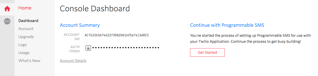
Get your API credentials. Navigate to your account's "dashboard". Write down (or otherwise keep handy) both the
Account SIDand yourAuth Token— you'll need those for the program.
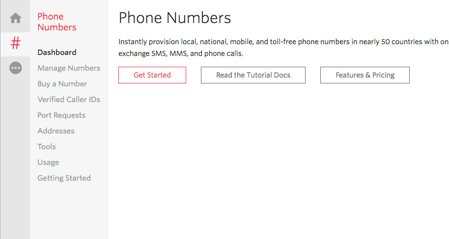
Set up a Twilio phone number. Start by heading to the Phone Numbers dashboard page.
Click the
Get Startedbutton
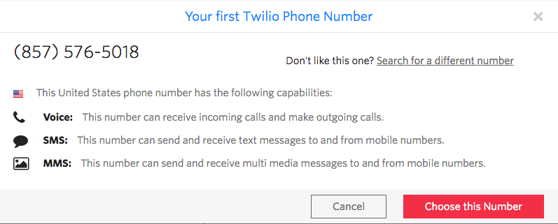
- Click the "Get your first Twilio phone number" button and walk through the steps.
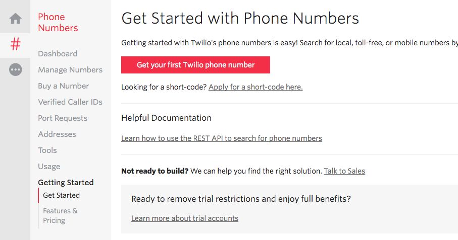
- Write down the number; you'll need this for the program too.
Twilio maintains an npm module that you can use. Install the Twilio module for Node.js by typing — or copying and pasting — the following command into your terminal:
npm install twilio
Type — or copy and paste — the following JavaScript code into your intruder-alert.js file:
language:javascript
var twilio = require("twilio");
var Tessel = require("tessel-io");
var five = require("johnny-five");
var board = new five.Board({
  io: new Tessel()
});

var accountSid = ""; // SID copied from www.twilio.com/console
var authToken = ""; // token copied from www.twilio.com/console

var sender = ""; // This is your Twilio phone number
var recipient = ""; // This is your own mobile phone number

var client = new twilio.RestClient(accountSid, authToken);

board.on("ready", () => {
  var door = new five.Switch({
    pin: "a2",
    invert: true,
  });

  door.on("open", () => {
    var details = {
      body: `Security Breach at ${Date.now()}`,
      from: sender,
      to: recipient,
    };

    client.messages.create(details, error => {
      if (error) {
        console.error(error.message);
      }
      // Success! Nothing else to do
    });
  });
});
Type — or copy and paste — the following into your terminal:
t2 run intruder-alert.js
When you remove the magnet, you should momentarily receive a text message warning you of an intruder!
Exploring the Code
The script instantiates a Twilio client object with the defined credentials. That object takes care of communicating back and forth with Twilio.
language:javascript
var accountSid = ""; // SID copied from www.twilio.com/console
var authToken = ""; // token copied from www.twilio.com/console

var sender = ""; // This is your Twilio phone number
var recipient = ""; // This is your own mobile phone number

var client = new twilio.RestClient(accountSid, authToken);
After the board is ready, a Switch is instantiated, just like before. But there is a change to the open event handler. When the door is opened:
door.on("open", () => {
  // 1. Define the details of the SMS to send
  // 2. Use the Twilio client to send the message
});
Fleshing that out:
language:javascript
door.on("open", () => {

  // SMS details
  var details = {
    body: `Security Breach at ${Date.now()}`,
    from: sender, // Twilio phone number
    to: recipient,  // You! (phone number)
  };

  // Send the SMS
  client.messages.create(details, error => {
    if (error) {
      console.error(error.message);
    }
    // Success! Nothing else to do
  });
});
The details object sets up a body for the text message (using a template literal and the JavaScript Date object), as well as sender and recipient phone numbers.
Then we rely on the Twilio client object for dispatching the message, invoking client.messages.create with the details object and also a callback function. If there is an error (the first argument to the callback function if so), log it to the console. Otherwise, we're good—the message was sent successfully.
Building Further
- Turn a time lapse camera on and off -- use a switch to turn on a time lapse camera app using tessel-av.
- Set an alarm -- use a switch to turn an alarm clock app on and off
Reading Further
- JavaScript — the programming language that you'll be using:
- Node.js — JavaScript runtime where your programs will be executed
- Johnny-Five — framework written in JavaScript for programming hardware interaction on devices that run Node.js.