Experiment Guide for the Johnny-Five Inventor's Kit
 rwaldron,
  reconbot,
  D___Run___,
  lyzadanger,
  Shawn Hymel
 Experiment 9: Using an H-Bridge Motor Controller
Introduction
Motors are simultaneously simple and complicated. Simple because they're a basic design: run current through 'em and they spin. Reverse the direction of the current, and they spin the other way. Give 'em more current, and they spin faster. But to choreograph the speed and direction of a motor or motors—that takes a little more doing.
In this experiment, you'll meet a device called an H-Bridge. It's a kind of sophisticated switch that lets you control up to two motors at a time. You can use an SPDT switch (like we used in Experiment 5: Reading an SPDT Switch to control the direction of the motors, and a potentiometer (Experiment 3: Reading a Potentiometer to control the speed.
We hope you are buckled in because this is going to be a wild ride!
Preflight Check
Whoa there, Turbo! If this is your first experiment with the Johnny-Five Inventor's Kit (J5IK) and the Tessel 2, there are a few things you gotta do first:Suggested Reading
The following tutorials provide in-depth background on some of the hardware concepts in this experiment:
Parts Needed
You will need the following parts for this experiment:
- 1x Tessel 2
- 1x Tessel 2 5V wall adapter
- 1x Breadboard
- 1x SparkFun Motor Driver
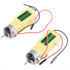
- 2x Hobby Gear Motor
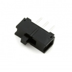
- 1x Switch
- 1x Potentiometer
- 20x Jumper Wires


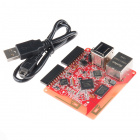
Tessel 2
DEV-13841Introducing the SparkFun Motor Driver
The SparkFun Motor Driver is a small circuit board that contains circuitry for controlling one or two motors at once. At the heart of the driver board is an H-Bridge, which allows you to control both direction and speed.
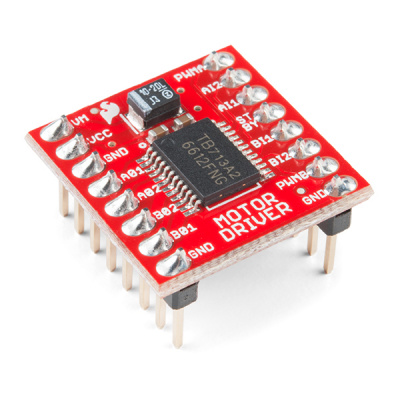
The H-Bridge board has 16 pins (don't panic; we'll guide you through the hookup). The pin names are printed on the bottom of the controller board:
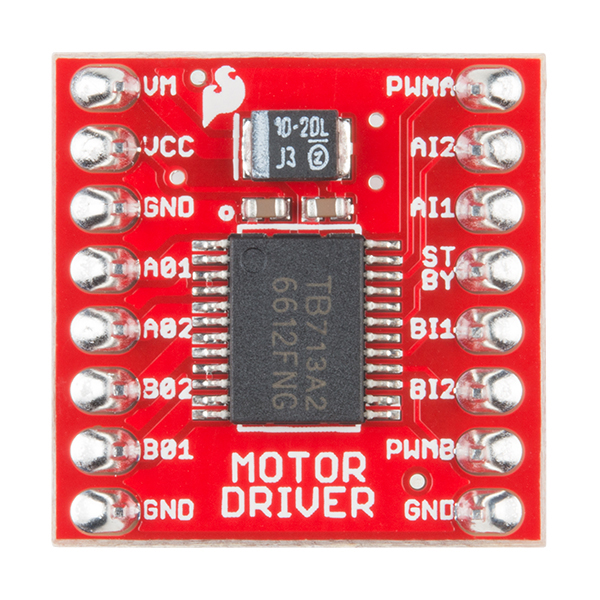
| PWMA | PWM signal for controlling the speed of motor A |
| AIN2 | Direction pin 2 for motor A |
| AIN1 | Direction pin 1 for motor A |
| STBY | Standby HIGH for board on, LOW for board off |
| BIN1 | Direction pin for motor B |
| BIN2 | Direction pin 2 for motor B |
| PWMB | PWM signal for controlling the speed of motor B |
| GND | Ground |
| VM | Motor power source 5V to 14V |
| VCC | Chip voltage (3.3V) |
| GND | Ground |
| A01 | Motor A connection |
| A02 | Motor A connection |
| B02 | Motor B Connection |
| B01 | Motor B Connection |
| GND | Ground |
Hardware Hookup
Are you ready to get your motor revving? Let's get the circuit built first!
| Polarized Components | Pay special attention to the component’s markings indicating how to place it on the breadboard. Polarized components can only be connected to a circuit in one direction. |
Build the H-Bridge Motor Circuit
Deep breaths. This circuit isn't so challenging to build—just pay attention and take it slowly. Anytime you work with motors, you have to be a smidge more careful about power sources. Motors cause power spikes, and need to be isolated from the (more delicate) circuitry in the Tessel and (potentially) your other components. You'll notice that there are two power sources for this project: 5V (VM) from the wall adapter for the motors, 3.3V from the Tessel 2 for the rest of the circuit (both share a common ground—that's normal). Anyway, here are a few warnings:
While building this circuit, refer to the wiring diagram and the images of the H-Bridge's pins above. Keep in mind that the photo of the H-Bridge board's different pins shows the bottom of the board. When the board is plugged in to the breadboard, the pins are flipped left to right. The steps below take that into account.
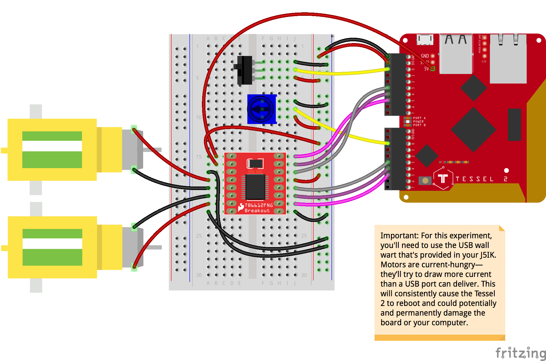
- Connect the H-Bridge board to the breadboard. Make sure to orient it in the direction shown in the diagram. The board should span the center notch.
- Using jumper wires, make connections between the H-Bridge and the power rail of the breadboard. The following steps assume you are looking at the H-Bridge board from the top, once it is connected to the breadboard.
- Connect the VCC pin (left side, second from top) to the supply power rail.
- Connect STBY (right side, fourth from top) to the supply power rail.
- Connect the three GND pins to the power rail. On the H-Bridge board, looking from the top, these pins are:
- Left side, third pin from top
- Left side, bottom pin
- Right side, bottom pin
- Connect the motors to the motor connection pins on the H-Bridge.
- Connect motor A's red and black wires to the H-Bridge's left side, fourth and fifth pins respectively.
- Connect the second motor's red and black wires to the H-Bridge's left side, sixth and seventh pins, respectively.
- Using jumper wires, connect H-Bridge pins for controlling motor A to pins on the Tessel 2.
- Connect the H-Bridge's PWMA pin (top right) to Tessel's Port A, Pin 5.
- Connect the H-Bridge's AIN2 pin (right side, second from top) to Tessel's Port A, Pin 4.
- Connect the H-Bridge's AIN1 pin (right side, third from top) to Tessel's Port A, Pin 3.
- Using jumper wires, connect H-Bridge pins for controlling motor B to pins on the Tessel 2.
- Connect the H-Bridge's PWMB pin (right side, second from bottom) to Tessel's Port B, Pin 5.
- Connect the H-Bridge's BIN2 pin (right side, third from bottom) to Tessel's Port B, Pin 4.
- Connect the H-Bridge's BIN1 pin (right side, fourth from bottom) to Tessel's Port B, Pin 3.
- Connect the potentiometer to the breadboard. Connect its ground and power pins to the power rail of the breadboard, using jumper wires. Connect its third pin to Tessel's Port B, Pin 0.
- Connect the SPDT switch to the breadboard. Connect its ground and power pins to the power rail of the breadboard, using jumper wires. Connect its third pin to Tessel's Port A, Pin 0.
- Connect 3.3V power and ground from the Tessel 2's 3.3V and GND pins to the breadboard's power rail using jumper wires.
- Connect 5V power to the H-Bridge board's VM (motor voltage) pin. Using a jumper wire, connect the H-Bridge VM pin (left side, top pin) to the 5V pin on the Tessel 2. If you're using the J5IK version of the Tessel 2, headers will be pre-soldered to the 5V power pins. On the Tessel board, the 5V pin is the bottom pin in the column of three pins in the header.
Spinning a Single Motor at Half Speed With Johnny-Five
To control a motor’s speed and direction requires three pins per motor. We'll start by controlling just one of the two motors.
While the circuit you created above includes both motors from your kit, as well as a switch and potentiometer, let's look at some basic code to control only one of them with just code. Open your favorite code editor, create a file called motor-single.js and save it in the j5ik/ directory. Type—or copy and paste—the following JavaScript code into your motor-single.js file:
language:javascript
var five = require("johnny-five");
var Tessel = require("tessel-io");
var board = new five.Board({
  io: new Tessel()
});

board.on("ready", () => {
  var motor = new five.Motor([ "a5", "a4", "a3" ]);

  motor.forward(128);
});
Type—or copy and paste—the following into your terminal:
t2 run motor-single.js
What You Should See
When this program runs, you will see that one of your motors is spinning at half speed. The speed is measured in terms of an 8-bit range: 0 is effectively stopped and 255 is top speed.
Exploring the Code
As with all Johnny-Five programs, after the board object has emitted the ready event, we can initialize a Motor instance:
language:javascript
var motor = new five.Motor([ "a5", "a4", "a3" ]);
Let's first talk about the argument that's passed to the Motor constructor:
language:javascript
[ "a5", "a4", "a3" ]
Undoubtedly you will recognize that these are pin names, but why these three pins? What do they mean?
To control a motor's speed and direction requires three pins per motor:
In this case, we're using a directional, dual-motor H-Bridge controller, which requires three pins per motor:
- One pin to control the speed of the motor.
- One pin to make the motor go in one direction.
- One pin to make the motor go in the opposite direction.
The speed of the motor is controlled using PWM (Pulse Width Modulation). The two direction pins are set HIGH or LOW to dictate the direction the motor spins.
Terminology for this stuff is a bit all over the place. Some guides and datasheets will show direction as clockwise or cw. Counter direction is also called counter-clockwise or ccw. It would be impossible for Johnny-Five to support all variations verbatim, so the Motor class attempts to simplify this by calling them pwm, direction (dir) and counter direction (cdir).
| Control Type/Role | Johnny-Five Motor Pin Name | Breakout Pin (Printed) |
|---|---|---|
| PWM | pwm |
PWMA or PWMB |
| Counter Direction | cdir |
AIN2 or BIN2 |
| Direction | dir |
AIN1 or BIN1 |
Different HIGH-LOW combinations on the dir and cdir pins cause different things to happen with the motor. The following table takes into account info from the TB6612FNG datasheet to illustrate how these pins are manipulated by the Motor instance internally:
| IN1 | IN2 | PWM | Results |
|---|---|---|---|
| H | H | ~ | Short Brake |
| L | H | ~ | CCW |
| H | L | ~ | CW |
| L | L | ~ | Stop |
OK, back to our code. Johnny-Five does as much as possible to simplify the code that you write, so this:
language:javascript
[ "a5", "a4", "a3" ]
Means:
language:javascript
[ pwm, dir, cdir ]
And is actually just a short hand for writing out the full pin definition:
language:javascript
var motor = new five.Motor({
  pins: {
    pwm: "a5",
    dir: "a4",
    cdir: "a3",
  }
});
Neat, right?!
The next line simply instructs the motor to spin "forward" (which is relative, based on how the two motor wires are attached to the output pins) at half speed (motor.forward(...) takes an 8-bit number, so 255 would be FULL STEAM AHEAD):
language:javascript
motor.forward(127);
And that's it!
Variation: Control a Single Motor Speed and Direction With Johnny-Five
Open your favorite code editor, create a file called motor-speed-direction.js and save it in the j5ik/ directory. Type—or copy and paste—the following JavaScript code into your motor-speed-direction.js file:
language:javascript
var five = require("johnny-five");
var Tessel = require("tessel-io");
var board = new five.Board({
  io: new Tessel()
});

board.on("ready", function() {
  var spdt = new five.Switch("a0");
  var throttle = new five.Sensor("b0");
  var motor = new five.Motor([ "a5", "a4", "a3" ]);

  spdt.on("open", () => {
    motor.stop().forward(motor.speed());
  });

  spdt.on("close", () => {
    motor.stop().reverse(motor.speed());
  });

  throttle.on("change", () => {
    motor.speed(throttle.value >> 2);
  });
});
Type—or copy and paste—the following into your terminal:
t2 run motor-speed-direction.js
What You Should See
Motor A can be controlled in two ways:
- When you flip the switch, the motor will change direction, maintaining its current speed.
- When the potentiometer is adjusted, the speed of the motor is changed accordingly.
Exploring the Code
If you haven't read the following, now is a good time:
After the board object has emitted the ready event, we can initialize Switch, Sensor and Motor instances:
language:javascript
var spdt = new five.Switch("a0"); // For the switch
var throttle = new five.Sensor("b0"); // For the potentiometer
var motor = new five.Motor([ "a5", "a4", "a3" ]); // For motor A
Then, register the event handlers that will turn switch state (open or closed) into motor direction:
language:javascript
spdt.on("open", () => {
  motor.stop().forward(motor.speed());
});

spdt.on("close", () => {
  motor.stop().reverse(motor.speed());
});
Finally, register an event handler for changes from the throttle sensor, which updates the speed of the motor.
As you learned in Experiment 3: Reading a Potentiometer, analog sensor input values are 10-bit (0--1023), but the motor speed needs to be an 8-bit (0--255) value. We can bit-shift the throttle value to get an 8-bit number (the two least significant bits on the right get discarded).
language:javascript
throttle.on("change", () => {
  motor.speed(throttle.value >> 2);
});
Variation: Control Multiple Motors' Speed and Direction With Johnny-Five
Open your favorite code editor, create a file called motor-multi-speed-direction.js and save it in the j5ik/ directory. Type—or copy and paste—the following JavaScript code into your motor-multi-speed-direction.js file:
language:javascript
var five = require("johnny-five");
var Tessel = require("tessel-io");
var board = new five.Board({
  io: new Tessel()
});

board.on("ready", function() {
  var spdt = new five.Switch("a0");
  var throttle = new five.Sensor("b0");
  var motors = new five.Motors([
    [ "a5", "a4", "a3" ],
    [ "b5", "b4", "b3" ],
  ]);
  var speed = 0;

  spdt.on("open", () => {
    motors.stop().forward(speed);
  });

  spdt.on("close", () => {
    motors.stop().reverse(speed);
  });

  throttle.on("change", () => {
    speed = throttle.value >> 2;
    motors.speed(speed);
  });
});
Type—or copy and paste—the following into your terminal:
t2 run motor-multi-speed-direction.js
What You Should See
Both motors are controlled by the switch and potentiometer inputs:
- When you flip the switch, the motors will change direction, maintaining current speed.
- When the potentiometer is adjusted, the speed of both motors is changed accordingly.
Exploring the Code
If you haven't read Experiment 2: Multiple LEDs, now is a good time.
After the board object has emitted the ready event, we can initialize a Switch and a Sensor like the last example. But instead of Motor, here the code uses a Motors instance:
language:javascript
var spdt = new five.Switch("a0");
var throttle = new five.Sensor("b0");
var motors = new five.Motors([
  [ "a5", "a4", "a3" ],
  [ "b5", "b4", "b3" ],
]);
Recall in Experiment 2: Multiple LEDs, you were introduced to collection classes, which allowed your program to initialize a "list" or "collection" of a specific component class ... that's what you're doing here as well.
Motors allows you to create two Motor instances that can be controlled simultaneously.
The variable speed keeps track of the current speed of both motors:
language:javascript
var speed = 0;
Then, register the event handlers that will turn switch state (open or closed) into motor direction. This is effectively the same as the previous iteration, except now we're using motors and setting the value from the speed variable:
language:javascript
spdt.on("open", () => {
  motors.stop().forward(speed);
});

spdt.on("close", () => {
  motors.stop().reverse(speed);
});
Finally, the event handler for throttle changes is updated to first update the speed variable, then set the speed of both motors:
language:javascript
throttle.on("change", () => {
  speed = throttle.value >> 2;
  motors.speed(speed);
});
Building Further
- Make a browser-based "remote control" that's served from an Express server, with commands transmitted over a socket provided by Socket.io.
- Attach your Tessel 2 and two motors to a Shadow Chassis with a USB and drive it.
Reading Further
- JavaScript — JavaScript is the programming language that you'll be using.
- Node.js — Node.js is the JavaScript runtime where your programs will be executed.
- Johnny-Five — Johnny-Five is a framework written in JavaScript for programming hardware interaction on devices that run Node.js.