Experiment Guide for the Johnny-Five Inventor's Kit
 rwaldron,
  reconbot,
  D___Run___,
  lyzadanger,
  Shawn Hymel
 Experiment 14: Driving a Seven-Segment Display
Introduction
You're flush with newfound knowledge about shift registers from Experiment 13: Controlling LEDs with a Shift Register. Now let's tackle another application of what you've learned: using a shift register to control a seven-segment display.
Preflight Check
Whoa there, Turbo! If this is your first experiment with the Johnny-Five Inventor's Kit (J5IK) and the Tessel 2, there are a few things you gotta do first:Suggested Reading
The following tutorial provides in-depth background on some of the hardware concepts in this experiment:
- You're flush with newfound knowledge about shift registers from Experiment 13: Controlling LEDs with a Shift Register
Parts Needed
You will need the following parts for this experiment:
- 1x Tessel 2
- 1x Breadboard
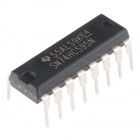
- 1x Shift Register
- 1x Seven-Segment Digit
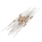
- 1x 100Ω Resistor
- 17x Jumper Wires


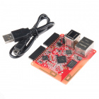
Tessel 2
DEV-13841Introducing the Seven-Segment Display

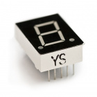
The seven-segment display is essentially eight LEDs in one. Different combinations of seven individual LEDs can be lit to represent decimal numbers (the eighth LED is a decimal point). This display is a common-anode display. If you flip the display assembly over, you will notice that the display has a whole bunch of pins. These pins (A--G) correspond with each segment of the display, with one (DP) for controlling the decimal point (the display in your kit may have two decimal points, but only one is wired).
These letters correspond with the following pins on the back of the display. You can use the following image and table to figure out the corresponding segment and pins to use for hookup.
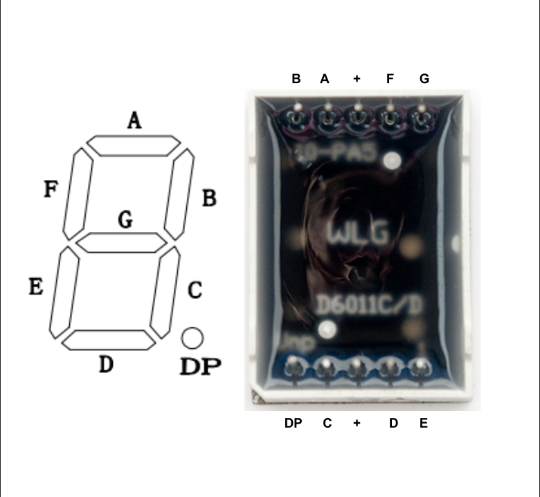
| Pin | Letter |
|---|---|
| 1 | E |
| 2 | D |
| 3 | + |
| 4 | C |
| 5 | DP |
| 6 | A |
| 7 | A |
| 8 | + (unused in this experiment) |
| 9 | F |
| 10 | G |
Hardware Hookup
This circuit is leveling you up from Experiment 13; it's time to get counting!
| Polarized Components | Pay special attention to the component’s markings indicating how to place it on the breadboard. Polarized components can only be connected to a circuit in one direction. |
Build the Seven-Segment Circuit
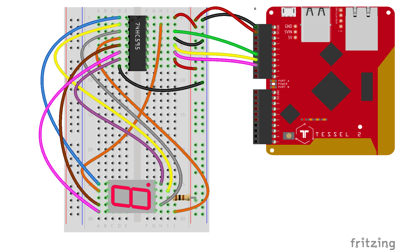
- Connect the shift register to the breadboard. Make sure the semi-circular notch is toward the top of the board.
- Connect the seven-digit display to the breadboard, near the bottom, with the decimal point on the right.
- Make the connections with jumper wires between the shift register and the seven-segment display as shown. There are eight connections, one for each of the shift register's output pins. You should have two remaining (non-connected) pins on the seven-segment display.
- Connect the middle (third down) pin of the seven-segment's right (decimal) side to the supply power rail through a 100Ω resistor (recall: this is a shared-anode component; we can use a single current-limiting resistor for all of the eight LEDs). This leaves one pin of the display not connected, which is expected.
- Make the connections between the shift register and the Tessel's GPIO pins. Shift register pins 14, 12 and 11 should be connected with jumper wires to Tessel 2's Port A, pins 3, 4 and 5, respectively (see wiring diagram).
- Connect the shift register to the power rail with four jumper cables (pins 8 and 13 to ground, pins 10 and 16 to supply).
Using a Shift Register to Control a Seven-Segment Digit With Johnny-Five
Open your favorite code editor, create a file called shift-register-digit.js and save it in the j5ik/ directory. Type—or copy and paste—the following JavaScript code into your shift-register-digit.js file:
language:javascript
var five = require("johnny-five");
var Tessel = require("tessel-io");
var board = new five.Board({
  io: new Tessel()
});

board.on("ready", () => {
  var register = new five.ShiftRegister({
    pins: [ "a3", "a5", "a4" ],
    isAnode: true,
  });
  var number = 0;

  board.loop(1000, () => {
    register.display(number);

    number++;

    if (number > 9) {
      number = 0;
    }
  });
});
Type—or copy and paste—the following into your terminal:
t2 run shift-register-digit.js
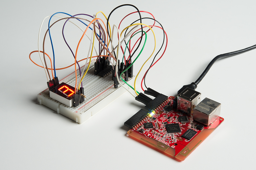
What You Should See
The seven segment display will count from 0 to 9 and start over.
Exploring the Code
Once the board object has emitted the ready event, the program initializes a ShiftRegister instance object that will be used to send data to the shift register component in the circuit. In Experiment 13: Shift Register + LEDs, we covered short-hand initializations, but there's a new isAnode property here:
language:javascript
var register = new five.ShiftRegister({
  pins: [ "a3", "a5", "a4" ],
  isAnode: true,
});
This tells the ShiftRegister component class to initialize an instance that knows how to encode and decode values for an anode digit display—the isAnode property tells ShiftRegister that we're working with a common-anode output device.
Unlike Experiment 13: Shift Register + LEDs, we don't have to get into the weeds about how to form each number from the various individual LEDs. Instead, we can use the display(0-9) method to display a complete number. Johnny-Five does the unglamorous work for us.
language:javascript
var number = 0;

board.loop(1000, () => {
  register.display(number);

  number++;

  if (number > 9) {
    number = 0;
  }
});
Variation: Creating a User Input Display
Instead of having the program simply print out the count, let's control the display with user input. Since we're running low on jumper wires, let's get creative with our input source. Go ahead and install the keypress module:
npm install keypress
This will allow us to respond to user input in the terminal itself and react accordingly.
Open your favorite code editor, create a file called input-display.js and save it in the j5ik/ directory. Type—or copy and paste—the following JavaScript code into your input-display.js file:
language:javascript
var keypress = require("keypress");
var five = require("johnny-five");
var Tessel = require("tessel-io");
var board = new five.Board({
  io: new Tessel(),
  repl: false,
});

keypress(process.stdin);

board.on("ready", function() {
  var register = new five.ShiftRegister({
    pins: [ "a3", "a5", "a4" ],
    isAnode: true,
  });
  var number = 0;

  register.display(number);

  process.stdin.on("keypress", (character, key) => {
    if (key) {
     if (key.name === "q") {
         process.exit(0);
      }

      if (key.name === "up") {
        number++;
      }

      if (key.name === "down") {
        number--;
      }

      if (number > 9) {
        number = 0;
      }

      if (number < 0) {
         number = 9
      }

    } else {
      number = character;
    }

    register.display(number);
  });

  process.stdin.setRawMode(true);
  process.stdin.resume();

  console.log("Press 'q' to quit.");
});
Type---or copy and paste---the following command into your terminal and press enter:
t2 run input-display.js
What You Should See
When you press the up or down key on your keyboard, the number displayed will increment by one, or decrement by one. When you press a number key, the number will change to that number.
Exploring the Code
The first addition is the newly required keypress module:
language:javascript
var keypress = require("keypress");
Because we'll be specifying our own handling of user keyboard input, the Board initialization now tells Johnny-Five not to automatically create a REPL, by settng a repl property to false:
language:javascript
var board = new five.Board({
  io: new Tessel(),
  repl: false,
});
And then, within the the board's ready event handler:
language:javascript
keypress(process.stdin);
This makes keypress pay attention to stuff going on in process.stdin (that's a stream for standard input, meaning, roughly, in this case, stuff typed into the Tessel's REPL). Next, we listen for those keypress events and do something with the data from them (hold that thought).
That's followed by setting process.stdin to raw mode and telling it to resume, which means "treat this as a raw device and keep going: open up the input flow and let 'er rip."
language:javascript
process.stdin.on("keypress", (character, key) => {
  // ...
});

process.stdin.setRawMode(true);
process.stdin.resume();
Within the handler, it's time to do something with the data we have from the keypress event:
language:javascript
if (key) {
  if (key.name === "q") {
    process.exit(0);
  }

  if (key.name === "up") {
    number++;
  }

  if (key.name === "down") {
    number--;
  }

  if (number > 9) {
    number = 0;
  }

  if (number < 0) {
    number = 9
  }
} else {
  number = character;
}

register.display(number);
First, the program checks if the key variable is set—if it is, then it knows it hasn't received a press from a number. For whatever reason, the keypress module doesn't treat presses on number keys as a "key," but only provides them as a character.
So, if the key variable is set, it's anything but a number; otherwise it is a number.
Now:
- If it's not a number, and it's a press of the "q" key, exit the program.
- If it's not a number, and it's a press of the "up" key, increment by 1.
- If it's not a number, and it's a press of the "down" key, decrement by 1.
- Then, "wrap" the number at 0 and 9, such that counts over 9 start back at 0 and counts less than 0 start back at 9.
- Finally, display the new number value on the seven segment device.
Building Further
- Add another button to make a counter that goes up and a counter that goes down.
Reading Further
- JavaScript — JavaScript is the programming language that you'll be using.
- Node.js — Node.js is the JavaScript runtime where your programs will be executed.
- Johnny-Five — Johnny-Five is a framework written in JavaScript for programming hardware interaction on devices that run Node.js.