Experiment Guide for the Johnny-Five Inventor's Kit
 rwaldron,
  reconbot,
  D___Run___,
  lyzadanger,
  Shawn Hymel
 Experiment 13: Controlling LEDs with a Shift Register
Introduction
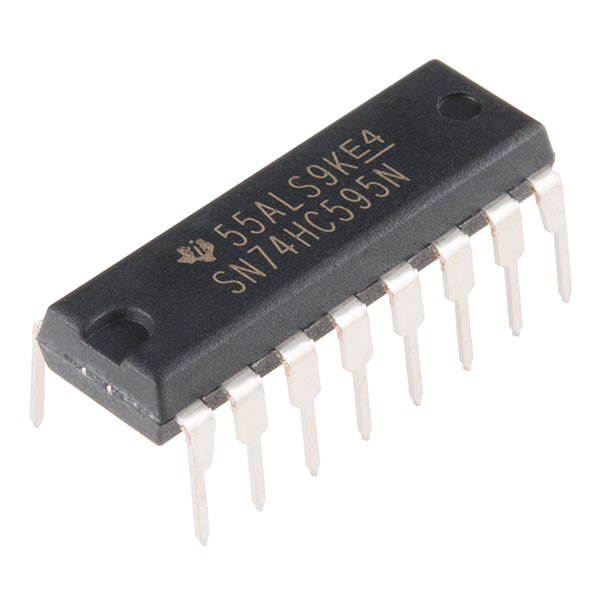
This experiment is the first time we'll use an Integrated Circuit (IC) all by itself with no breakout board or other support. We'll use a shift register to give you control over an additional eight outputs, while using up only three pins on the Tessel 2. Using the shift register in this experiment, you can control eight—count 'em, eight!—LEDs. That's a new record for us!
Preflight Check
Whoa there, Turbo! If this is your first experiment with the Johnny-Five Inventor's Kit (J5IK) and the Tessel 2, there are a few things you gotta do first:Suggested Reading
The following tutorials provide in-depth background on some of the hardware concepts in this article:
Parts Needed
You will need the following parts for this experiment:
- 1x Tessel 2
- 1x Breadboard
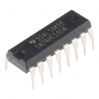
- 1x Shift Register
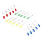
- 8x Standard LEDs
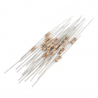
- 8x 100Ω Resistor
- 17x Jumper Wires


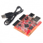
Tessel 2
DEV-13841Introducing the Shift Register
The kind of shift register used in this experiment takes a byte of data (8 bits) and breaks it up, using each bit to determine the logic level of its eight output pins. For example, the message:
01101001
would result in the following states on the shift register's individual output pins:
LOW-HIGH-HIGH-LOW-HIGH-LOW-LOW-HIGH
Each bit in the sent byte, then, determines the state of its associated output pin. The shift register is able to give you extra outputs (eight, while using only three pins on the Tessel 2) because it takes serial data and converts it to parallel output.
You can think of the inside of a shift register as a big train-switching yard. A train (byte) arrives, and, like all of the other trains that come to this place, it is eight cars long. Each car in the train represents a single bit, and is either full (1) or empty (0). The train is disassembled; each car is switched onto its own track and waits. Once all of the cars are in place and the engine-master gives the all clear, the cars exit the yard on their assigned track (shift register output pin). Full cars (1s) will cause their output pins to go HIGH while empty cars (0s) will cause their output pins to go LOW. Bytes representing different orders of 1s and 0s cause different patterns of LOW and HIGH states from the shift register's output pins.
If you have eight LEDs connected to the shift register's output pins, you could turn them all on by sending the message 11111111, or turn them all off by sending the message 0000000.
There are 16 pins on the shift register included with this kit. If you orient the shift register chip with the semi-circular notch upward, the pins are numbered starting from the top-left pin. Pins 1 through 8 run top-to-bottom on the left side of the chip. Pins 9 to 16 run bottom-to-top on the right side. Read that again to avoid confusion: pins on the right are numbered bottom-to-top (pin 16 is the top-right pin).
The pins on the shift register do different things. Pin 15 and pins 1--7 are the output pins—those will get connected to the LEDs. A few pins need to be connected to power and ground. The three connections between the SR and the Tessel 2 are a data connection (to send those trains of bytes), a clock connection (to keep everyone in sync) and a latch (for, in part, controlling when data gets pushed out to output pins). You won't have to mess around with the clock and latch stuff—other than telling Johnny-Five which Tessel 2 pins are connected to those shift-register pins. You just have to decide what data to send to the shift register.
Hardware Hookup
Does this circuit look a little shifty to you? Fear not! Let's build it and then master using the shift register.
| Polarized Components | Pay special attention to the component’s markings indicating how to place it on the breadboard. Polarized components can only be connected to a circuit in one direction. |
Build the Circuit
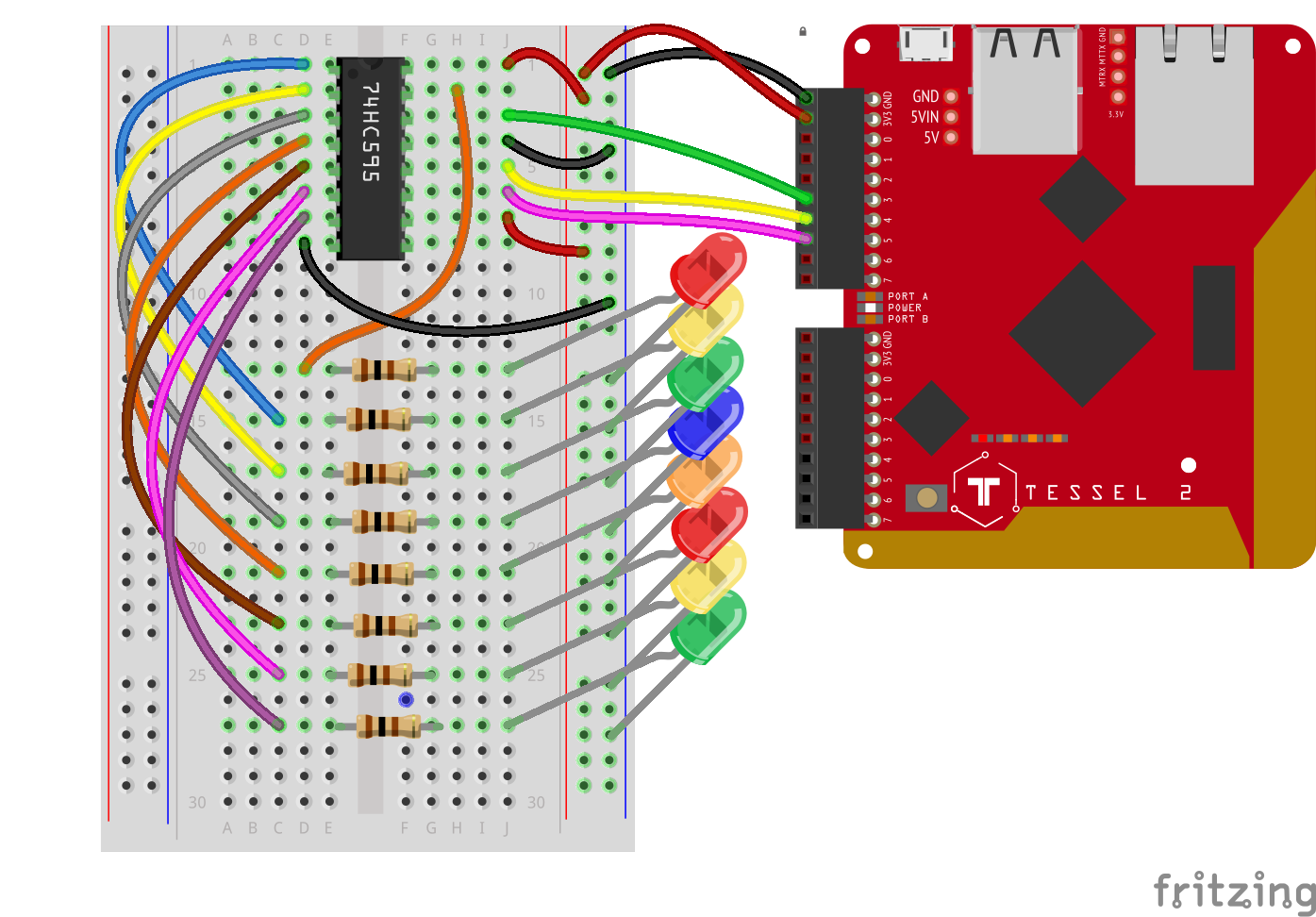
- Connect the shift register to the breadboard. Look for the semi-circular divot at one of the ends of the chip. That end of the chip should be oriented toward the top of the breadboard. Plug the shift register in so that it spans the center notch.
- Connect the eight LEDs. For each, plug the anode (longer leg) into a terminal row on the breadboard and the cathode (shorter leg) directly into the ground power rail.
- Connect the current-limiting resistors for the LEDs. Each 100Ω resistor should span the center notch.
- Some of the shift register's pins need to be connected to power or ground. Using jumper wires, connect shift register pins 16 and 10 to the supply power rail. Connect shift register pins 8 and 13 to the ground power rail.
- Connect each of the shift register's output pins to the LED it will control, using jumper wires. Start by connecting the shift register's Pin 15 to the first LED. Then connect the shift register's pins 1--7 to the rest of the LEDS, as shown in the wiring diagram.
- Connect the shift register to the Tessel 2. Shift register pins 14, 12 and 11 should be connected with jumper wires to Tessel 2's Port A, pins 3, 4 and 5, respectively (see wiring diagram).
- Use jumper wires to connect the Tessel 2's 3.3V and GND pins to the power rails of the breadboard.
Using a Shift Register to Display 8-Bit Values With Johnny-Five
Open your favorite code editor, create a file called shift-register-bits.js and save it in the j5ik/ directory. Type—or copy and paste—the following JavaScript code into your shift-register-bits.js file:
language:javascript
var five = require("johnny-five");
var Tessel = require("tessel-io");
var board = new five.Board({
  io: new Tessel()
});

board.on("ready", () => {
  var register = new five.ShiftRegister({
    pins: {
      clock: "a5",
      data: "a3",
      latch: "a4",
    }
  });

  var output = 0b10000000;

  board.loop(100, () => {
    output = output > 0 ? output >> 1 : 0b10000000;
    register.send(output);
  });
});
Type—or copy and paste—the following into your terminal:
t2 run shift-register-bits.js
What You Should See
The program cycles through each LED, lighting one at a time, repeating the pattern forever.
Exploring the Code
Once the board object has emitted the ready event, the program initializes a ShiftRegister instance object that will be used to send data to the shift register component in the circuit.
language:javascript
var register = new five.ShiftRegister({
  pins: {
    data: "a3",
    clock: "a5",
    latch: "a4",
  }
});
In Experiment 9: Using an H-Bridge Motor Controller you learned about Johnny-Five's simplified argument forms, which can applied to every component class constructor; here, we can actually rewrite the above arguments as:
language:javascript
[ "a3", "a5", "a4" ]
Which means:
language:javascript
[ data, clock, latch ]
Therefore, the entire initialization could also be written as:
language:javascript
var register = new five.ShiftRegister([ "a3", "a5", "a4" ]);
Much nicer! These argument forms are illustrated in the Johnny-Five ShiftRegister component initialization API docs.
The next line sets an initial value of 128, represented as Binary Integer Literal:
language:javascript
var bits = 0b10000000;
We briefly looked at Binary Integer Literals in Experiment 3: Reading a Potentiometer, but this time we'll take a closer look. Open the Node.js REPL by typing node and pressing ENTER in your terminal. Once open, type any of the following, each followed by pressing the ENTER key:
language:javascript
0b0
0b01
0b0101
0b1010
0b1111
0b10000
0b1111111
0b10000000
0b11111111
0b100000000
These are called Binary Integer Literals because they are literally the binary representation (1s and 0s) of an integer. Each 1 and/or 0 represents a single bit. The 0b prefix tells JavaScript to interpret the 0s and 1s that follow as a binary number.
The result of each, in order, must be:
language:javascript
0
1
5
10
15
16
127
128
255
256
As a nasty hack, you could figure out the minimum number of bits necessary to represent, in binary, a given number by writing:
language:javascript
var value = 255;
console.log(value.toString(2).length); // 8
All numbers have a toString(radix) method, which converts a number to a String. The radix argument tells what base to use when translating the number. 2 is binary. 10 is decimal. It can accept any radix between 2 and 36.
Since we can now literally see how many bits are in a number, we can move onto the next piece of code:
language:javascript
board.loop(100, () => {
  output = output > 0 ? output >> 1 : 0b10000000;
  register.send(output);
});
The first line in the looping callback function is assigning a new value to the variable output based on whether the present value of output is greater than zero.
If it is, then shift the actual bits of the present value of output one place to the right (this shoves one of the 0s off of the right side). If it's not greater than zero, assign the value 128 (shown in binary integer literal form, 0b10000000), which will make the LED pattern start back at the beginning again. The last line of the function sends the output to the shift register.
Here's the effect of every call to the loop callback, as it would appear over eight iterations:
| B7 | B6 | B5 | B4 | B3 | B2 | B1 | B0 |
|---|---|---|---|---|---|---|---|
| 1 | 0 | 0 | 0 | 0 | 0 | 0 | 0 |
| 0 | 1 | 0 | 0 | 0 | 0 | 0 | 0 |
| 0 | 0 | 1 | 0 | 0 | 0 | 0 | 0 |
| 0 | 0 | 0 | 1 | 0 | 0 | 0 | 0 |
| 0 | 0 | 0 | 0 | 1 | 0 | 0 | 0 |
| 0 | 0 | 0 | 0 | 0 | 1 | 0 | 0 |
| 0 | 0 | 0 | 0 | 0 | 0 | 1 | 0 |
| 0 | 0 | 0 | 0 | 0 | 0 | 0 | 1 |
B means "Bit", (i.e., Bit 7 = B7). B0 is the right-most bit.
Binary Counting
Since we have eight LEDs, and we know it's helpful to think of our output in terms of range as 8-bit, let's visually count out the full range of 8-bit numbers (0--255) using the LEDs! Open your favorite code editor, create a file called shift-register-count.js and save it in the j5ik/ directory. Type—or copy and paste—the following JavaScript code into your shift-register-count.js file:
language:javascript
var five = require("johnny-five");
var Tessel = require("tessel-io");
var board = new five.Board({
  io: new Tessel()
});

board.on("ready", function() {
  var register = new five.ShiftRegister([ "a3", "a5", "a4" ]);
  var output = 0b00000000;
  board.loop(100, () => {
    register.send(output);
    output++;
    if (output > 0b11111111) {
      output = 0b00000000;
    }
  });
});
Instead of bit-shifting using the bitwise operator >>, output++ increments the value of output by 1 on each iteration. If output gets too big (greater than 255, or 0b11111111), reset it to 0 (0b00000000).
Type—or copy and paste—the following into your terminal:
t2 run shift-register-count.js
What You Should See
The LEDs will be lit to represent each number from 0--255 in its binary form, one number at a time.
Building Further
- Try using Johnny-Five's
Expanderclass, with the74HC595controller to treat each LED as a singleLedinstance.- Use an
Ledsinstance class with anExpanderinstance to control all of the LEDs as you did in Experiment 2: Multiple LEDs.
- Use an
Reading Further
- JavaScript — JavaScript is the programming language that you'll be using:
- Node.js — Node.js is the JavaScript runtime where your programs will be executed.
- Johnny-Five — Johnny-Five is a framework written in JavaScript for programming hardware interaction on devices that run Node.js.