SIK Experiment Guide for the Arduino 101/Genuino 101 Board (Chinese)
This Tutorial is Retired!
This tutorial covers concepts or technologies that are no longer current. It's still here for you to read and enjoy, but may not be as useful as our newest tutorials.
 D___Run___
 实验 18:读取板载加速度计
简介
在实验 13 中,您尝试使用不同输入来控制马达的速度和方向。在本实验中,您将进行类似的操作,不过是使用 Arduino 101 开发板上的板载重力感应器作为输入。
重力感应器测量在不同方向上应用于传感器的重力。如果重力感应器在四处移动,则您可以从重力感应器数据推断出许多信息。不过在它静止时,也可以方便地确定向下的方向。地球的重力是始终存在的力,可以由重力感应器进行测量。我们将这样使用它确定 Arduino 101 开发板的方向,在其中让马达向前驱动、向后驱动或不执行任何操作。让我们开始吧!
所需部件
您需要以下部件:
- 1x 实验电路板
- 1x Arduino 101 或 Genuino 101 开发板
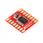
- 1x SparkFun 马达驱动器
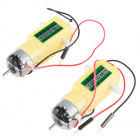
- 1x 42:1 业余级齿轮马达
- 13x 跳线
没有 SIK?
如果您要执行本实验,但又没有 SIK,那么我们建议您使用这些部件:


您还需要一个 Arduino 101 或 Genuino 101 开发板。

Arduino 101
DEV-13787
Genuino 101
DEV-13984推荐阅读
继续进行本实验之前,我们建议您熟悉以下教程中的概念:
重力感应器简介
重力感应器是测量加速度的设备,而加速度是物体速度的变化速率。其测量单位是米/平方秒 (m/s2) 或 G 力 (g)。在地球行星上,一个 G 力等于 9.8 m/s2,但是这会因海拔而稍有不同(并且在不同行星上,会由于万有引力的变化而是不同值)。重力感应器可用于感应系统中的振动或方向应用。
硬件接线
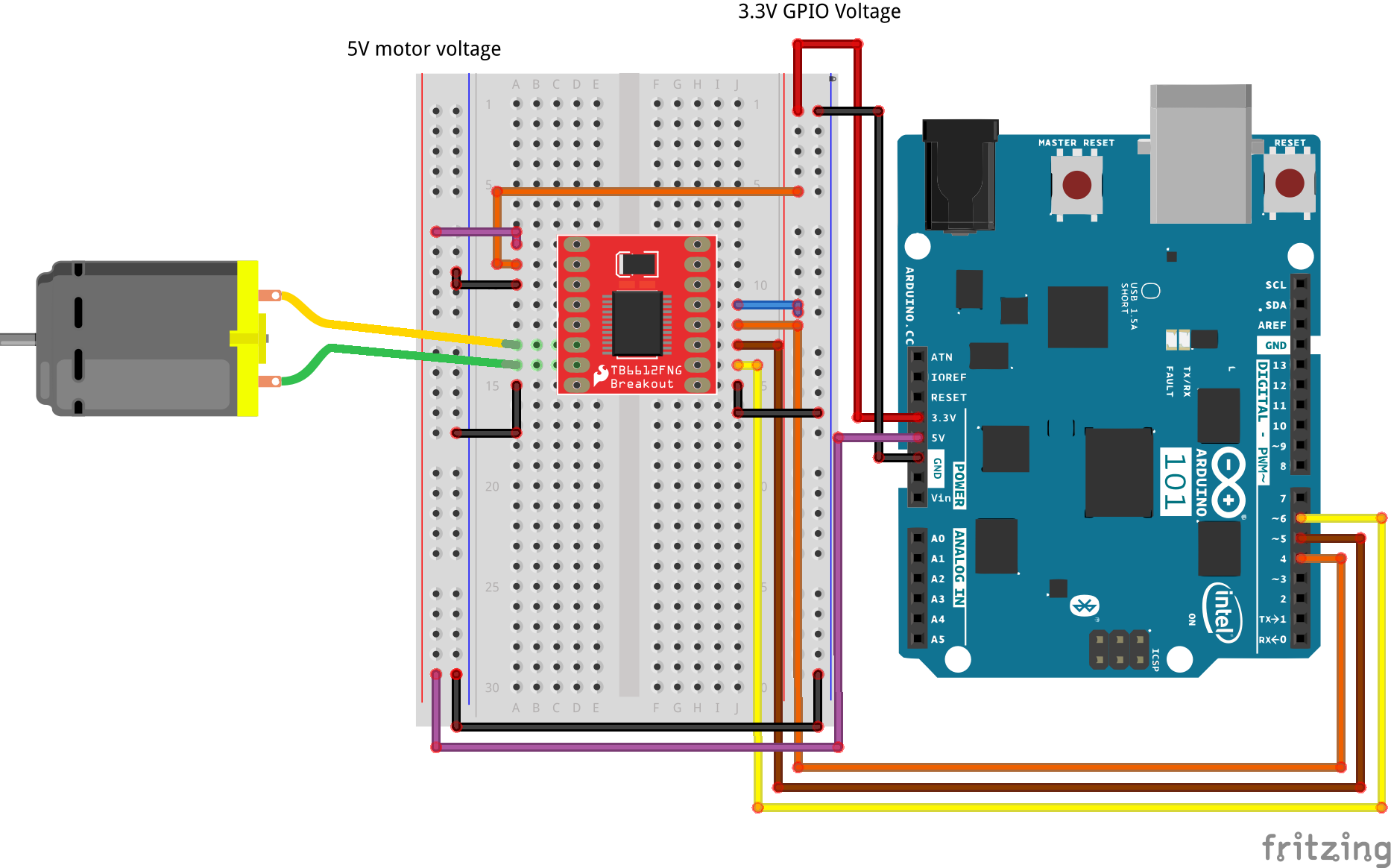
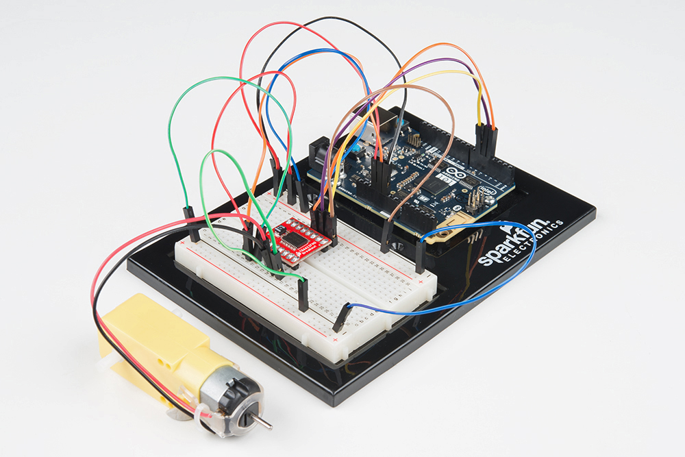
是否准备好开始对每个部件进行接线?请查看下面的接线图以了解如何连接每个部件。
| 极化组件 | 请特别注意组件用于指示如何在实验电路板上放置它的标记。极化组件只能按一个方向连接到电路。 |
实验的接线图
打开草图
在计算机上打开 Arduino IDE 软件。采用 Arduino 语言进行编码可控制电路。通过访问您先前下载并置于“示例”文件夹中的“101 SIK 指南代码”,来打开用于电路 18 的代码。
要打开该代码,请转到:文件 > 示例 > 101 SIK 指南代码 > Circuit_18
还可以将以下代码复制并粘贴到 Arduino IDE 中。点击“上传”,然后查看发生的情况!
language:cpp
/*
SparkFun Inventor's Kit
Example sketch 18

Controlling a Motor Using an Accelerometer

  Use the on-board accelerometer of the 101 board as an input to control
  a motor based on its orientation in space. If you tilt the 101 to the left,
  the motor spins in one direction; tilted to the right, it spins the opposite direction; and if it
  is flat, the motor stops.

This sketch was written by SparkFun Electronics, and based on the Orientation example
in the CurieIMU Library Examples
This code is completely free for any use.
Visit http://learn.sparkfun.com/products/2 for SIK information.
Visit http://www.arduino.cc to learn more about Arduino.
*/

#include "CurieIMU.h"

const int DIR_A = 4;
const int DIR_B = 5;
const int PWM = 6;

// previous orientation (for comparison). Start at (-1) to start with

void setup()
{
 //set motor control pins to OUTPUT
pinMode(DIR_A, OUTPUT);
pinMode(DIR_B, OUTPUT);
pinMode(PWM, OUTPUT);

 // Start the acceleromter
 CurieIMU.begin();

// Set the accelerometer range to 2G
CurieIMU.setAccelerometerRange(2);
}

void loop()
{
 // read accelerometer:
 int x = CurieIMU.readAccelerometer(X_AXIS);
 int y = CurieIMU.readAccelerometer(Y_AXIS);
 int z = CurieIMU.readAccelerometer(Z_AXIS);

 // calculate the absolute values, to determine the largest
 int absX = abs(x);
 int absY = abs(y);
 int absZ = abs(z);

if ( (absZ > absX) && (absZ > absY))
{
 // base orientation on Z
 if (z > 0)
 {
  brake();
 }
}

 //else if Y is greater than X and Z its on edge
 else if ( (absY > absX) && (absY > absZ))
 {
  // if Y is positive orientation (digital pins up)and is set to 1
  if (y > 0)
  {
    forward();
  }
  //the Y is in the negative orientation (analog pins up) and is set to 2
  else
  {
    reverse();
  }
}
}
//custom function for driving the motor forward
void forward()
{
  digitalWrite(DIR_A, HIGH);
  digitalWrite(DIR_B, LOW);
  digitalWrite(PWM, HIGH);
}

//custom function for driving the motor in reverse
void reverse()
{
  digitalWrite(DIR_A, LOW);
  digitalWrite(DIR_B, HIGH);
  digitalWrite(PWM, HIGH);
}

//custom function for braking the motor
void brake()
{
  digitalWrite(DIR_A, LOW);
  digitalWrite(DIR_B, LOW);
  digitalWrite(PWM, LOW);
}
要注意的代码
#include "CurieIMU.h"
Arduino 的串行端口可以用于接收以及发送数据。因为数据可能随时到达,所以 Arduino 101 开发板会存储(或“缓冲”)进入端口的数据,直到您准备好使用数据。Serial.available() 命令会返回端口已收到,但是尚未由草图使用的字符数。零表示没有数据到达。
int x = CurieIMU.readAccelerometer(X_AXIS);
我们通过将常量 X_AXIS 传递给 CurieIMU 的 readAccelerometer 方法来读取重力感应器值。这会从传感器返回实时读数。要读取其他轴,可以向该方法传递常数 X_AXIS、Y_AXIS 和 Z_AXIS。
int absX = abs(x);
在本实验中,我们不必关心是正值还是负值。我们只需知道哪个值是最大值,我们可以从中进行决策。我们使用了“abs()”函数,它采用数字的绝对值(基本上是去掉 (-) 符号)。我们将该值存储在一个名为“absX”的本地变量中,以便如果我们要访问原始 x 值,则仍可以执行该操作。
language:cpp
//if Z axis is greater than X and Y its facing upright
if ( (absZ > absX) && (absZ > absY))
{
 // base orientation on Z
 if (z > 0)
 {
  brake();
 }
}

 //else if Y is greater than X and Z its on edge
 else if ( (absY > absX) && (absY > absZ))
 {
  // if Y is positive orientation (digital pins up)and is set to 1
  if (y > 0)
  {
    forward();
  }
  //the Y is in the negative orientation (analog pins up) and is set to 2
  else
  {
    reverse();
  }
}
使重力感应器读数成为绝对值之后,我们可以使用 if() 语句比较它们。在本实验中,我们只希望比较与向左和向右倾斜开发板有关的值,不过仍会采用三个轴来进行确定。例如,如果 Y 大于 X,则 Y 轴指向下方(指向重力方向)。我们随后进行最终比较,了解它是否大于 0 以确保它处于正方向。我们基于这些比较设置马达的方向。
应看到的情况
代码上传到 101 开发板之后,拿起 101 开发板并向左倾斜它(模拟输入针脚向下)。马达应开始按一个方向运行。现在朝相反方向倾斜它(数字 GPIO 针脚向下),马达应按相反方向运行。将开发板平放时,马达应停止。如果不是这样,请查看下面的“故障诊断”部分。
故障诊断
马达未旋转
确保对马达控制器接线正确。因为这里有许多导线!
仍未成功
仔细检查代码是否上传到 101 开发板。有时将数据上传到 101 开发板需要一段时间,因此请耐心等候!
仍未运行
Arduino 有时会与计算机断开连接。尝试拔下它,然后重新插入 USB 端口。