SIK Experiment Guide for the Arduino 101/Genuino 101 Board (Chinese)
This Tutorial is Retired!
This tutorial covers concepts or technologies that are no longer current. It's still here for you to read and enjoy, but may not be as useful as our newest tutorials.
 D___Run___
 实验 11:使用晶体管
简介
在前面的实验中,您使用了伺服马达。现在,我们将处理马达旋转问题。这需要使用晶体管,它可以切换的电流量比 101 开发板更大。您将使用晶体管打开和关闭马达 -- 是的,一个闪烁的马达!
所需部件
您需要以下部件:
- 1x 实验电路板
- 1x Arduino 101 或 Genuino 101 开发板
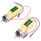
- 1x 48:1 比率齿轮马达
- 1x 100Ω 电阻
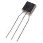
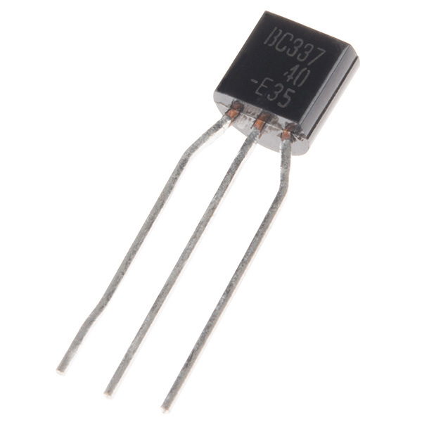
- 1x NPN 晶体管
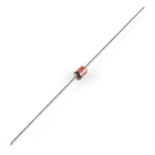
- 1x 二极管 1N4148
- 7x 跳线
没有 SIK?
如果您要执行本实验,但又没有 SIK,那么我们建议您使用这些部件:


Zener Diode - 5.1V 1W
COM-10301
您还需要一个 Arduino 101 或 Genuino 101 开发板。

Arduino 101
DEV-13787
Genuino 101
DEV-13984推荐阅读
继续进行本实验之前,我们建议您熟悉以下教程中的概念:
晶体管简介
晶体管可以描述为小型电子开关。它使您可以通过较小电流控制较大电流负载,而不必承担烧坏敏感组件的风险。晶体管具有三个针脚:集电极、发射极和基极。电流只能按一个方向流到晶体管中 -- 流经集电极并从发射极流出。要控制电流的流动,您需要向基极施加小量电流。这一小电流可以是数字属性(开或关)或模拟属性(通过使用 PWM 和 analogWrite() 函数)。较大电流将随较小电流的变化而相应变化。
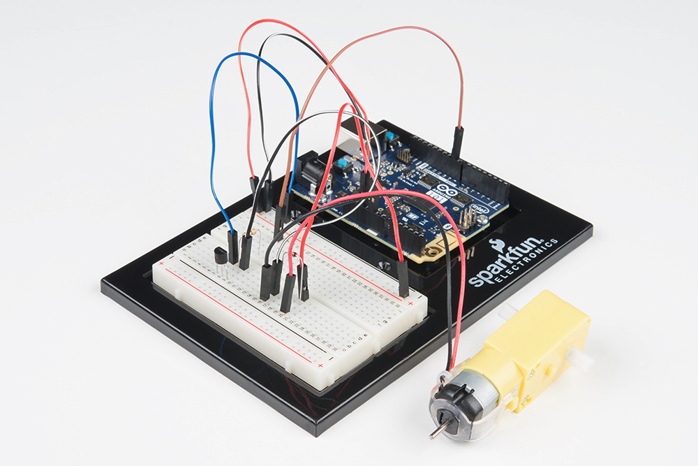
硬件接线
是否准备好开始对每个部件进行接线?请查看下面的接线图以了解如何连接每个部件。
| 极化组件 | 请特别注意组件用于指示如何在实验电路板上放置它的标记。极化组件只能按一个方向连接到电路。 |
请注意:构建电路时,请注意不要混用晶体管和温度传感器;它们几乎是相同的。在晶体管主体上查找“P2N2222A”。
实验的接线图
什么是续流二极管?
当旋转马达突然关闭时,其内部的磁场会瓦解,从而生成电压峰值。这可能会损坏晶体管。为了防止出现这种情况,我们使用“续流二极管”,它可使电压峰值“绕过”晶体管。将具有带子的二极管一端(阴极)连接到 5V。将二极管的另一端(阳极)连接到马达上的黑色导线。
打开草图
在计算机上打开 Arduino IDE 软件。采用 Arduino 语言进行编码可控制电路。通过访问您先前下载并置于“示例”文件夹中的“101 SIK 指南代码”,来打开用于电路 11 的代码。
要打开该代码,请转到:文件 > 示例 > 101 SIK 指南代码 > Circuit_11
还可以将以下代码复制并粘贴到 Arduino IDE 中。点击“上传”,然后查看发生的情况!
language:cpp
/*
SparkFun Inventor's Kit
Example sketch 11

SPINNING A MOTOR

  Use a transistor to spin a motor at different speeds.

This sketch was written by SparkFun Electronics,
with lots of help from the Arduino community.
This code is completely free for any use.
Visit http://learn.sparkfun.com/products/2 for SIK information.
Visit http://www.arduino.cc to learn more about Arduino.
*/

// constant pin for the transistor connected to the motor
const int motorPin = 9;

void setup()
{
  //set motorPin as OUTPUT
  pinMode(motorPin, OUTPUT);
}

void loop()
{
  // Here we've used comments to disable some of the examples.
  // To try different things, uncomment one of the following lines
  // and comment the other ones. See the functions below to learn
  // what they do and how they work.

   motorOnThenOff();
  // motorOnThenOffWithSpeed();
  // motorAcceleration();
}

// This function turns the motor on and off like the blinking LED.
// Try different values to affect the timing.
void motorOnThenOff()
{
  // milliseconds to turn the motor on
  int onTime = 3000;
  // milliseconds to turn the motor off
  int offTime = 3000;

  // turn the motor on (full speed)
  digitalWrite(motorPin, HIGH);
  // delay for onTime milliseconds
  delay(onTime);
  // turn the motor off
  digitalWrite(motorPin, LOW);
  // delay for offTime milliseconds
  delay(offTime);
}

// This function alternates between two speeds.
// Try different values to affect the timing and speed.
void motorOnThenOffWithSpeed()
{
  // between 0 (stopped) and 255 (full speed)
  int Speed1 = 200;
   // milliseconds for speed 1
  int Time1 = 3000;

  // between 0 (stopped) and 255 (full speed)
  int Speed2 = 50;
  // milliseconds to turn the motor off
  int Time2 = 3000;

  // turns the motor On
  analogWrite(motorPin, Speed1);
  // delay for onTime milliseconds
  delay(Time1);
  // turns the motor Off
  analogWrite(motorPin, Speed2);
  // delay for offTime milliseconds
  delay(Time2);
}

// This function slowly accelerates the motor to full speed,
// then back down to zero.
void motorAcceleration()
{
  // milliseconds between each speed step
  int speed;
  int delayTime = 20;

  // accelerate the motor
  for(speed = 0; speed <= 255; speed++)
  {
    // set the new speed
    analogWrite(motorPin,speed);
    // delay between speed steps
    delay(delayTime);
  }

  // decelerate the motor
  for(speed = 255; speed >= 0; speed--)
  {
    // set the new speed
    analogWrite(motorPin,speed);
    // delay between speed steps
    delay(delayTime);
  }
}
应看到的情况
如果您正确装配了电路的组件,还验证/上传了正确代码,则直流马达应旋转。如果您的电路未运行,请查看“故障诊断”部分。
故障诊断
马达未旋转
如果您使用自己的晶体管,请按照数据表仔细检查引出线是否与所使用的晶体管兼容(许多情况并不兼容)。
仍未成功
如果您使用自己的马达,请仔细检查它是否适用于 5 伏,以及它是否没有消耗太多功率。
仍未运行
Arduino 有时会与计算机断开连接。尝试拔下它,然后重新插入 USB 端口。