SIK Experiment Guide for the Arduino 101/Genuino 101 Board (Chinese)
This Tutorial is Retired!
This tutorial covers concepts or technologies that are no longer current. It's still here for you to read and enjoy, but may not be as useful as our newest tutorials.
 D___Run___
 实验 2:读取电位计
简介
在此电路中,您将使用电位计。您将学习如何通过读取传感器并将它存储为变量,然后将它用作延迟时间,来使用电位计控制闪烁 LED 的时间。
所需部件
您需要以下部件:
- 1x 实验电路板
- 1x Arduino 101 或 Genuino 101 开发板
- 1x LED
- 1x 100Ω 电阻
- 7x 跳线
- 1x 电位计
没有 SIK?
如果您要执行本实验,但又没有 SIK,那么我们建议您使用这些部件:


您还需要一个 Arduino 101 或 Genuino 101 开发板。

Arduino 101
DEV-13787
Genuino 101
DEV-13984推荐阅读
继续进行本实验之前,我们建议您熟悉以下教程中的概念:
电位计简介
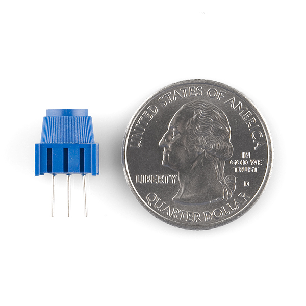
电位计是基于电阻的模拟传感器,可基于其旋钮的旋转来更改其内部电阻。电位计具有一个内部分压器,使您可以通过微控制器(101 开发板)读取中央针脚上的电压变化。要对电位计进行接线,请将两个外部针脚连接到电源电压(在此电路中是 3.3V)和接地。这两个针脚的连接位置并不重要,只要一个连接到电源,另一个连接到接地即可。中央针脚随后连接到模拟输入针脚,以便 101 开发板可以测量电压变化。扭动旋钮时,传感器读数会发生变化!
注:工具包中所含的电位计上具有三个标记,可帮助您确定针脚所插入到的实验电路板行。
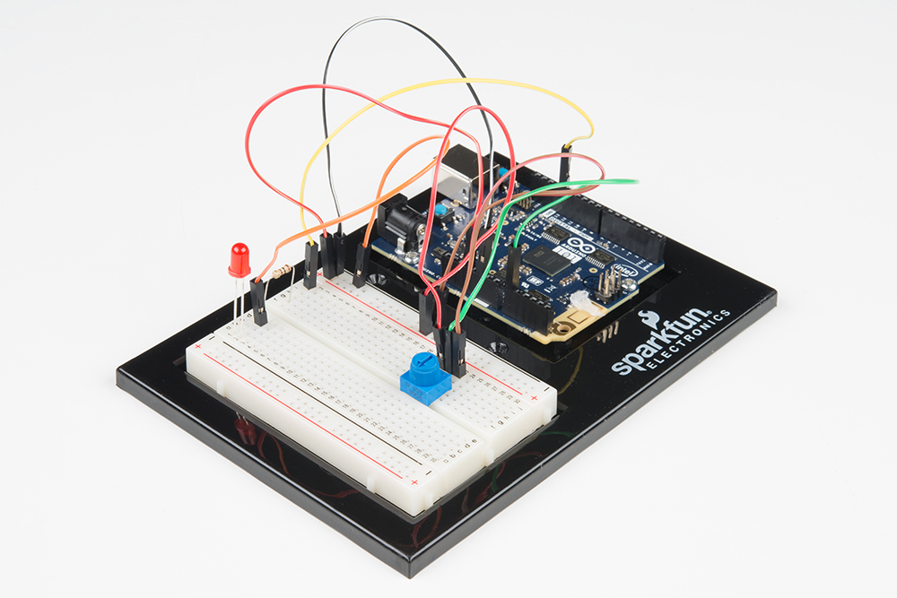
硬件接线
是否准备好开始对每个部件进行接线?请查看下面的接线图和接线表以了解如何连接每个部件。
| 极化组件 | 请特别注意组件用于指示如何在实验电路板上放置它的标记。极化组件只能按一个方向连接到电路。在表中,极化组件使用黄色警告三角突出显示。 |
实验的接线图

打开草图
在计算机上打开 Arduino IDE 软件。采用 Arduino 语言进行编码可控制电路。通过访问您先前下载并置于“示例”文件夹中的“101 SIK 指南代码”,来打开用于电路 2 的代码。
要打开该代码,请转到:文件 > 示例 > 101 SIK 指南代码 > Circuit_02
将以下代码复制并粘贴到 Arduino IDE 中。点击“上传”,然后查看发生的情况!
language:cpp
/* SparkFun Inventor's Kit
Example sketch 02

POTENTIOMETER

  Measure the position of a potentiometer and use it to
  control the blink rate of an LED. Turn the knob to make
  it blink faster or slower!

This sketch was written by SparkFun Electronics,
with lots of help from the Arduino community.
This code is completely free for any use.
Visit http://learn.sparkfun.com/products/2 for SIK information.
Visit http://www.arduino.cc to learn about Arduino.
*/

//Create global variables (variables that can be used anywhere in our sketch)

// Here we're creating a variable called "sensorPin" of type "int"
// and initializing it to have the value "0," which is the analog input pin the pot is     //conected to.
int sensorPin = 0;

// Variable for storing the pin number that the LED is connected to
int ledPin = 13;

// this function runs once when the sketch starts up
void setup()
{
  //set ledPin (13) as an OUTPUT
  pinMode(ledPin, OUTPUT);
}

// this function runs repeatedly after setup() finishes
void loop()
{

  //create a local variable (variable that can only be used inside of loop() to store       //a sensor value called sensorValue
  int sensorValue;

  //use the analogRead() function to read sensorPin and store the value in sensorValue
  sensorValue = analogRead(sensorPin);

  // Turn the LED on
  digitalWrite(ledPin, HIGH);

  delay(sensorValue);

  // Turn the LED off
  digitalWrite(ledPin, LOW);

 //delay for the value of sensorValue
  delay(sensorValue);

  //loop back to the top
}
要注意的代码
int sensorValue;
“变量”是可能在代码中更改的值的占位符。您必须先引入(或“声明”)变量,然后才能使用它们;此处您要声明一个名为 sensorValue 的变量,其类型为“int”(整数)。请记住,变量名称区分大小写!
sensorValue = analogRead(sensorPin);
使用 analogRead() 函数读取模拟针脚上的值。analogRead() 采用一个参数,即要使用的模拟针脚(“sensorPin”),并返回一个介于 0(0 伏)和 1023(3.3 伏)之间的数字(“sensorValue”)。
delay(sensorValue);
微控制器非常快,能够每秒运行数千行代码。为了减慢其速度以便我们可以查看它所执行的操作,我们通常在代码中插入延迟。delay() 以毫秒为单位进行计数;一秒等于 1000 毫秒。
应看到的情况
您应看到 LED 闪烁根据电位计而加快或减慢。如果它未运行,请确保正确装配了电路以及验证了代码并将它上传到开发板,或查看“故障诊断”部分。
故障诊断
偶发运行
这最可能是由于与电位计针脚之间的连接稍微有些接触不良。解决此问题的方法通常可以是按下电位计,或将电位计电路移动到实验电路板上的其他某个位置。
未运行
确保没有意外地将滑动片(中央针脚,即电位计中的电阻元件)连接到数字针脚 0 而不是模拟针脚 0(电源针脚下方的针脚行)。
LED 未亮起
LED 只能按一个方向运行。仔细检查连接。