SIK Experiment Guide for the Arduino 101/Genuino 101 Board (Chinese)
This Tutorial is Retired!
This tutorial covers concepts or technologies that are no longer current. It's still here for you to read and enjoy, but may not be as useful as our newest tutorials.
 D___Run___
 实验 7:读取光敏电阻
简介
在实验 2 中,您使用了电位计,它会基于旋钮的转动来更改电阻,进而更改模拟输入针脚所读取的电压。在此电路中,您将使用光敏电阻,它会基于传感器收到的光量来更改电阻。您将读取房间的光量值,在房间黑暗时使 LED 亮起,在房间明亮时使它熄灭。就是这样;您将构建一个夜间照明灯!
所需部件
您需要以下部件:
- 1x 实验电路板
- 1x Arduino 101 或 Genuino 101 开发板
- 1x LED
- 1x 100Ω 电阻
- 7x 跳线
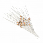
- 1x 光敏电阻
- 1x 10K 电阻
没有 SIK?
如果您要执行本实验,但又没有 SIK,那么我们建议您使用这些部件:


您还需要一个 Arduino 101 或 Genuino 101 开发板。

Arduino 101
DEV-13787
Genuino 101
DEV-13984光敏电阻简介
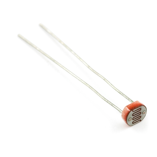
光敏电阻会基于对它照射的光量来更改其电阻。要将此光敏电阻与 101 开发板结合使用,您需要使用一个 10K 欧姆电阻构建一个分压器,如本实验的接线图所示。101 开发板无法读取电阻的变化,只能读取电压的变化。通过分压器可以将电阻的变化转换为对应的电压值。
通过分压器可以在基于电压的系统中使用基于电阻的传感器(如光敏电阻)。随着您探索其他传感器,您将发现更多类似于光敏电阻只有两个针脚的基于电阻的传感器。要将它们与 101 开发板结合使用,您需要构建一个分压器(类似于本实验中的分压器)。如需了解有关电阻的更多常规信息,请查看我们有关电阻的教程以及我们有关分压器的教程。
注:确保在分压器中使用 10K 欧姆电阻以及此工具包中的传感器。否则您会获得奇怪且不一致的结果。
硬件接线
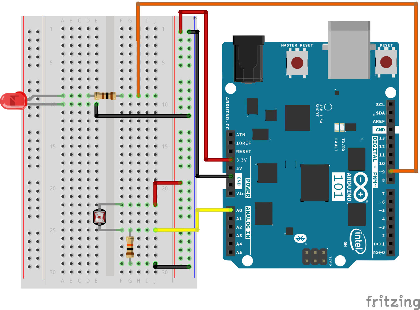
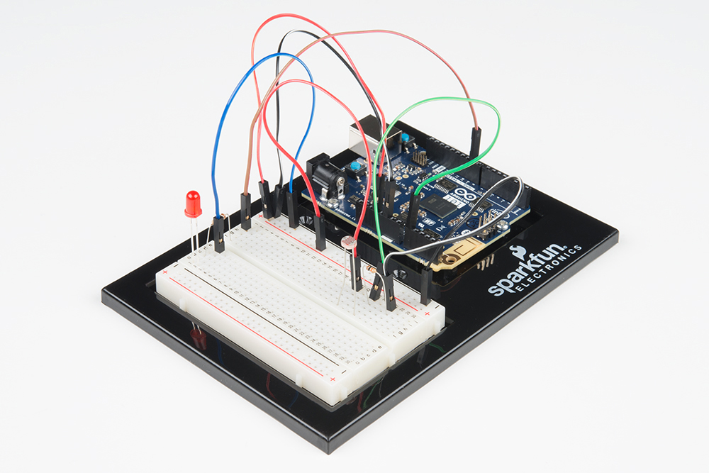
是否准备好开始对每个部件进行接线?请查看下面的接线图以了解如何连接每个部件。
| 极化组件 | 请特别注意组件用于指示如何在实验电路板上放置它的标记。极化组件只能按一个方向连接到电路。 |
实验的接线图
打开草图
在计算机上打开 Arduino IDE 软件。采用 Arduino 语言进行编码可控制电路。通过访问您先前下载并置于“示例”文件夹中的“101 SIK 指南代码”,来打开用于电路 7 的代码。
要打开该代码,请转到:文件 > 示例 > 101 SIK 指南代码 > Circuit_07
还可以将以下代码复制并粘贴到 Arduino IDE 中。点击“上传”,然后查看发生的情况!
language:cpp
/*
SparkFun Inventor's Kit
Example sketch 07

PHOTORESISTOR

  Read a photoresistor (light sensor) to detect "darkness" and turn on an LED when it is "dark" and turn back off again when it is "bright."

This sketch was written by SparkFun Electronics,
with lots of help from the Arduino community.
This code is completely free for any use.
Visit http://learn.sparkfun.com/products/2 for SIK information.
Visit http://www.arduino.cc to learn more about Arduino.
*/

// As usual, we'll create constants to name the pins we're using.
// This will make it easier to follow the code below.

const int sensorPin = 0;
const int ledPin = 9;

// We'll also set up some global variables for the light level a calibration value and     //and a raw light value
int lightCal;
int lightVal;

void setup()
{
  // We'll set up the LED pin to be an output.
  pinMode(ledPin, OUTPUT);
  lightCal = analogRead(sensorPin);
  //we will take a single reading from the light sensor and store it in the lightCal        //variable. This will give us a prelinary value to compare against in the loop
}

void loop()
{
  //Take a reading using analogRead() on sensor pin and store it in lightVal
  lightVal = analogRead(sensorPin);

  //if lightVal is less than our initial reading (lightCal) minus 50 it is dark and         //turn pin 9 HIGH. The (-50) part of the statement sets the sensitivity. The smaller       //the number the more sensitive the circuit will be to variances in light.
  if(lightVal < lightCal - 50)
  {
    digitalWrite(9,HIGH);
  }

  //else, it is bright, turn pin 9 LOW
  else
  {
    digitalWrite(9,LOW);
  }

}
要注意的代码
lightCal = analogRead(sensorPin); lightCal 是校准变量。101 开发板在设置中采用光传感器的单个读数,并在循环中使用此值与 lightVal 进行比较。此值在循环中不会更改,因为它是在设置函数中设置的。要更新此值,可以按“重置”按钮或关闭再打开开发板。
if(lightVal < lightCal -50) 如果在循环中不断更新的光量值变量小于在设置中设置的校准值减去 50,则表示黑暗,LED 应亮起。此语句的 (-50) 部分是灵敏度值。该值越高,电路的灵敏度便越低;该值越低,便对光照条件更灵敏。
应看到的情况
您应看到 LED 在房间黑暗时亮起,在变亮时熄灭。尝试将手盖住传感器,然后移开。如果它未运行,请确保正确装配了电路以及验证了代码并将它上传到开发板,或查看“故障诊断”部分。
故障诊断
LED 不亮
您可能在上传代码时使影子覆盖了传感器。确保传感器暴露在房间的环境光线中,然后按“主重置”按钮或重新上传代码。这会重置设置中的校准值。
仍未完全运行
您的逻辑语句可能错误。仔细检查代码,并尝试将灵敏度级别调低或调高一点。确保 if() 语句后面没有分号。这是常见错误,并且难以发现!