SIK Experiment Guide for the Arduino 101/Genuino 101 Board (Chinese)
This Tutorial is Retired!
This tutorial covers concepts or technologies that are no longer current. It's still here for you to read and enjoy, but may not be as useful as our newest tutorials.
 D___Run___
 实验 13:马达驱动器和输入
简介
在实验 12 中,您使用了马达驱动器板来控制马达的方向和速度。问题在于您必须对马达的方向和速度进行硬编码。使用马达的大多数应用都允许用户控制马达的速度和方向,这非常类似于您操纵自己的汽车。在本实验中,我们将添加两个输入并使用它们控制马达的方向和速度。
您是否准备好运行您的马达了?让我们开始吧!
所需部件
您需要以下部件:
- 1x 实验电路板
- 1x Arduino 101 或 Genuino 101 开发板
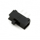
- 1x SPDT 开关
- 1x 10K 电位计
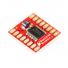
- 1x SparkFun 马达驱动器板
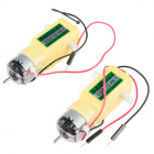
- 1x 48:1 比率齿轮马达
- 20x 跳线
没有 SIK?
如果您要执行本实验,但又没有 SIK,那么我们建议您使用这些部件:


您还需要一个 Arduino 101 或 Genuino 101 开发板。

Arduino 101
DEV-13787
Genuino 101
DEV-13984硬件接线
是否准备好开始对每个部件进行接线?请查看下面的接线图以了解如何连接每个部件。
| 极化组件 | 请特别注意组件用于指示如何在实验电路板上放置它的标记。极化组件只能按一个方向连接到电路。 |
实验的接线图

打开草图
在计算机上打开 Arduino IDE 软件。采用 Arduino 语言进行编码可控制电路。通过访问您先前下载并置于“示例”文件夹中的“SIK 指南代码”,来打开用于电路 13 的代码。
要打开该代码,请转到:文件 > 示例 > SIK 指南代码 > Circuit_13
还可以将以下代码复制并粘贴到 Arduino IDE 中。点击“上传”,然后查看发生的情况!
language:cpp
/*
SparkFun Inventor's Kit
Example sketch 13

SparkFun Motor Controller with Inputs

  Use the inputs to manually set the direction and speed of a motor.

This sketch was written by SparkFun Electronics,
with lots of help from the Arduino community.
This code is completely free for any use.
Visit http://learn.sparkfun.com/products/2 for SIK information.
Visit http://www.arduino.cc to learn more about Arduino.
*/
 //define the two direction logic pins and the speed / PWM pin
 const int DIR_A = 5;
 const int DIR_B = 4;
 const int PWM = 6;

 //define the input pins
 const int switchPin = 10;
 const int potPin = 0;

 void setup()
 {
  //set all pins as output
  pinMode(DIR_A, OUTPUT);
  pinMode(DIR_B, OUTPUT);
  pinMode(PWM, OUTPUT);
  //set the switchPin as INPUT
  pinMode(switchPin, INPUT);
  }

void loop()
{
//read the value from the potentiometer and divide
//it by 4 to get a 0-255 range. Store the value in
//the speed variable
int speed = analogRead(potPin) / 4;

 //read the value of the switch and store it in the
 //direction variable.

//if the value of direction is HIGH drive forward at
//a speed set by the speed variable, else drive reverse
//at a speed set by the speed variable.
if (digitalRead(switchPin) == HIGH)
{
  forward(speed);
}
else
 {
 reverse(speed);
 }
}

//create a custom function that defines moving forward
//the forward() function accepts one parameter and that is
//the speed at which you want to drive forward (0-255)
 void forward(int spd)
 {
 //motor contoller direction pins set to forward
 digitalWrite(DIR_A, HIGH);
 digitalWrite(DIR_B, LOW);

  //write the speed by using the parameter of spd
 analogWrite(PWM, spd);
  }

//create a custom function that defines moving in reverse
//the reverse() function accepts one parameter and that is
//the speed at which you want to drive in reverse (0-255)
void reverse(int spd)
{
//set motor controller pins to reverse
digitalWrite(DIR_A, LOW);
digitalWrite(DIR_B, HIGH);

 //write the speed by using the parameter of spd
 analogWrite(PWM, spd);
 }
这些可怕的大型函数采用单个值作为参数:速度。每个函数因而接受该值并将它应用于 analogWrite() 函数(而不是自定义函数)。自定义函数是清理代码的好方法,还可使它更加模块化并且可用于其他应用。请注意!您正在编写自己的库。
应看到的情况
您应能够通过反转 SPDT 开关来控制马达的方向,随后可通过电位计控制速度。继续进行并尝试调整两个输入以确保它们都运行正常并且马达响应这些输入。

故障诊断
马达只按一个方向旋转
仔细检查开关的接线,还要仔细检查 if() 语句以确保该语句后面没有分号。
此外,仔细检查以确保对待机针脚进行了正确接线(连接到 3.3V)。