SIK Experiment Guide for the Arduino 101/Genuino 101 Board (Chinese)
This Tutorial is Retired!
This tutorial covers concepts or technologies that are no longer current. It's still here for you to read and enjoy, but may not be as useful as our newest tutorials.
 D___Run___
 实验 8:使用 RGB 混合颜色
简介
在此电路中,您将使用多个电位计。您在实验 1 中使用了单个电位计。现在我们将更进一步,使用三个电位计!为何使用三个?您将使用每个电位计分别控制一个 RGB LED 的三种颜色(红色、绿色和蓝色)的亮度,以便形成一些比您在实验 3 中所使用的基本颜色更丰富的颜色。
拿出您的画笔,准备好绘制彩虹!
您需要以下部件:
- 1x 实验电路板
- 1x Arduino 101 或 Genuino 101 开发板
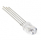
- 1x 共阴极 RGB LED
- 3x 100Ω 电阻
- 15x 跳线
- 3x 电位计
没有 SIK?
如果您要执行本实验,但又没有 SIK,那么我们建议您使用这些部件:


您还需要一个 Arduino 101 或 Genuino 101 开发板。

Arduino 101
DEV-13787
Genuino 101
DEV-13984推荐阅读
继续进行本实验之前,我们建议您熟悉以下教程中的概念:
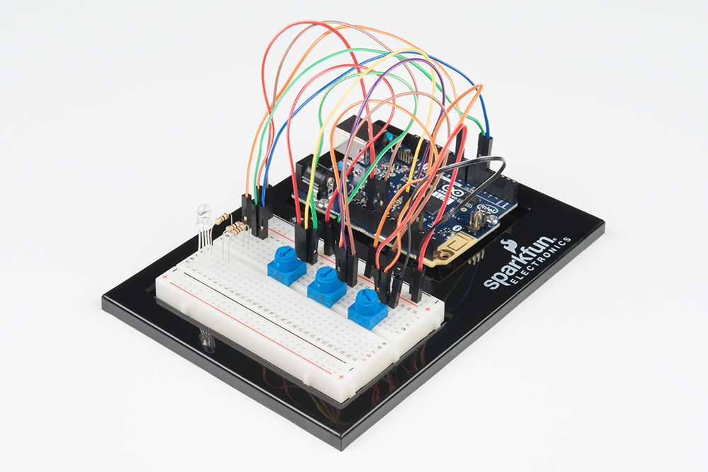
硬件接线
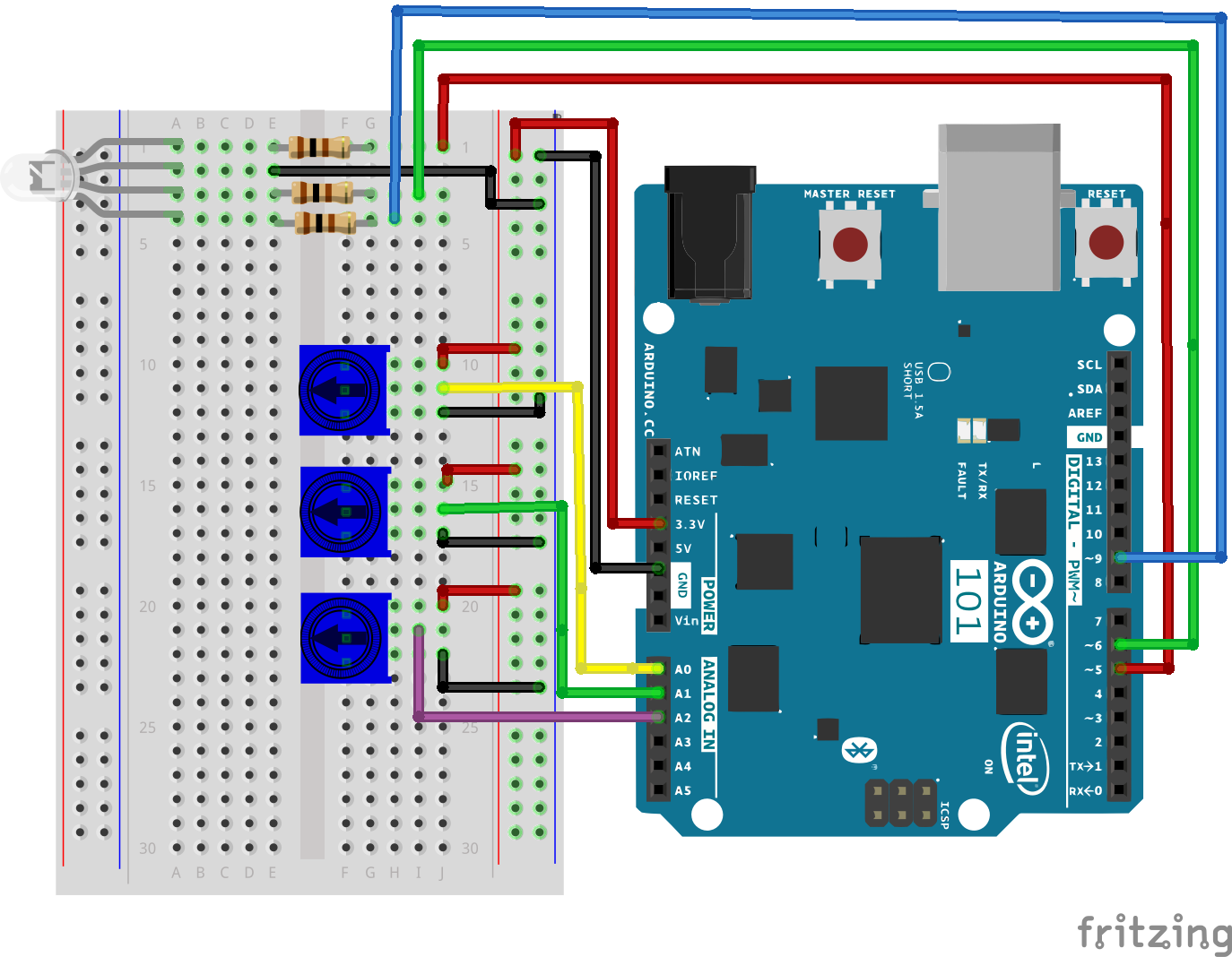
是否准备好开始对每个部件进行接线?请查看下面的接线图和接线表以了解如何连接每个部件。
| 极化组件 | 请特别注意组件用于指示如何在实验电路板上放置它的标记。极化组件只能按一个方向连接到电路。在表中,极化组件使用黄色警告三角突出显示。 |
实验的接线图
打开草图
在计算机上打开 Arduino IDE 软件。采用 Arduino 语言进行编码可控制电路。通过访问您先前下载并置于“示例”文件夹中的“SIK 指南代码”,来打开用于电路 8 的代码。
要打开该代码,请转到:文件 > 示例 > SIK 指南代码 > Circuit_08
将以下代码复制并粘贴到 Arduino IDE 中。点击“上传”,然后查看发生的情况!
language:cpp
/* SparkFun Inventor's Kit
Example sketch 08

POTENTIOMETER

  Measure the position of each potentiometer and map it to
  the red, green and blue values! Then write those values to the RGB LED.

This sketch was written by SparkFun Electronics,
with lots of help from the Arduino community.
This code is completely free for any use.
Visit http://learn.sparkfun.com/products/2 for SIK information.
Visit http://www.arduino.cc to learn more about Arduino.
*/

//create constants for the three analog input pins
const int redPot = 0;
const int greenPot = 1;
const int bluePot = 2;

//create constants for the three RGB pulse width pins
const int redPin = 5;
const int greenPin = 6;
const int bluePin = 9;

//create variables to store the red, green and blue values
int redVal;
int greenVal;
int blueVal;

void setup()
{
  //set the RGB pins as outputs
  pinMode(redPin, OUTPUT);
  pinMode(greenPin, OUTPUT);
  pinMode(bluePin, OUTPUT);
}

void loop()
{
  //read the three analog input pins and store their value to the color variables
  redVal = analogRead(redPot);
  greenVal = analogRead(greenPot);
  blueVal = analogRead(bluePot);

  //use the map() function to scale the 10 bit (0-1023) analog input value to an 8 bit
  //(0-255) PWM, or analogWrite() signal. Then store the new mapped value back in the
  //color variable

  redVal = map(redVal, 0, 1023, 0, 255);
  greenVal = map(greenVal, 0, 1023, 0, 255);
  blueVal = map(blueVal, 0, 1023, 0, 255);

  // use the analogWrite() function to write the color values to their respective
  // RGB pins.
  analogWrite(redPin, redVal);
  analogWrite(greenPin, greenVal);
  analogWrite(bluePin, blueVal);
}
要注意的代码
analogWrite(6,233); analogWrite 函数用于对 101 开发板的针脚 9、6、5 和 3 上的 PWM 进行控制。可以写入处于 0 - 255 范围内的值,其中 255 表示完全亮起,0 表示完全熄灭。
lightLevel = map(lightLevel, 0, 1023, 0, 255);
参数
map(value, fromLow, fromHigh, toLow, toHigh)
value:要映射的数字
fromLow:值当前范围的下限
fromHigh:值当前范围的上限
toLow:值目标范围的下限
toHigh:值目标范围的上限
当我们使用 analogRead() 读取模拟信号时,它会是介于 0 到 1023 之间的数字。但是当我们要使用 analogWrite() 驱动 PWM 针脚时,它需要介于 0 到 255 之间的数字。我们可以使用 map() 函数将较大范围“压缩”为较小范围。请参阅 Arduino 的映射参考页面以了解详细信息。
应看到的情况
您在调整三个电位计时应看到 RGB LED 更改颜色。每个电位计分别控制一种特定颜色(红色、绿色和蓝色)。当所有电位计都调整为最大值时,您应看到 RGB 发出白光。当它们全都调整为最小值时,RGB 应完全熄灭。如果不是这样,请查看下面的“故障诊断”部分。
故障诊断
偶发运行
这最可能是由于与电位计针脚之间的连接稍微有些接触不良。解决此问题的方法通常可以是按下电位计,或将电位计电路移动到实验电路板上的其他某个位置。
未运行
确保没有意外地将滑动片(中央针脚,即电位计中的电阻元件)连接到数字针脚 0 而不是模拟针脚 0。+(电源针脚下方的针脚行)。
LED 未亮起?
LED 只能按一个方向运行。仔细检查连接。