SIK Experiment Guide for the Arduino 101/Genuino 101 Board (Chinese)
This Tutorial is Retired!
This tutorial covers concepts or technologies that are no longer current. It's still here for you to read and enjoy, but may not be as useful as our newest tutorials.
 D___Run___
 实验 20:使用板载实时时钟 (RTC)
简介
微控制器十分擅长依据自己的计时方式“守时”。我们的意思是指其运行时间;它们按照内部时钟信号来运行,该信号使您可以跟踪自加电以来的毫秒数和微秒数。但是微控制器没有任何方法来了解实际时间,而实际时间是我们所有人用作日常工作和计划的基础的时间。
在本实验中,您将设置时钟,然后在 LCD 屏幕(您已在实验 17 中学习了如何使用它)上显示日期和时间。
注:101 开发板没有用于 RTC(实时时钟)的备用电池,因此如果您拔下开发板或电池耗尽,则必须在代码中重置 RTC 或开发使您可以调整时间的电路。
所需部件
您需要以下部件:
- 1x 实验电路板
- 1x Arduino 101 或 Genuino 101 开发板
- 1x 电位计
- 1x 3.3V LCD
- 16x 跳线
没有 SIK?
如果您要执行本实验,但又没有 SIK,那么我们建议您使用这些部件:


您还需要一个 Arduino 101 或 Genuino 101 开发板。

Arduino 101
DEV-13787
Genuino 101
DEV-13984推荐阅读
继续进行本实验之前,我们建议您熟悉以下教程中的概念:
实时时钟 (RTC) 简介
微控制器在保持运行时间(执行其作业所需的时序)方面表现优异。微控制器通过可跟踪自加电以来的毫秒数。但是,它们不擅长跟踪我们人类所使用的时间(“实际时间”)。微控制器使用实时时钟 (RTC) 来跟踪设置的起始点和不断前进的时间。
RTC 可跟踪时钟的小时、分钟和秒以及日历的天、月和年。在 101 开发板上,这要求您在首次加电时设置时间和日期。从该时间点起,它应该保持准确的时间。您随后可以使用时间触发事件在特定时间或日期发生,甚至可将它用作时间戳来记录数据。
注:如果 101 开发板断电,则您需要在代码中重置时钟。此外,RTC 是 101 开发板的板载组件,无需进行进一步接线。
硬件接线
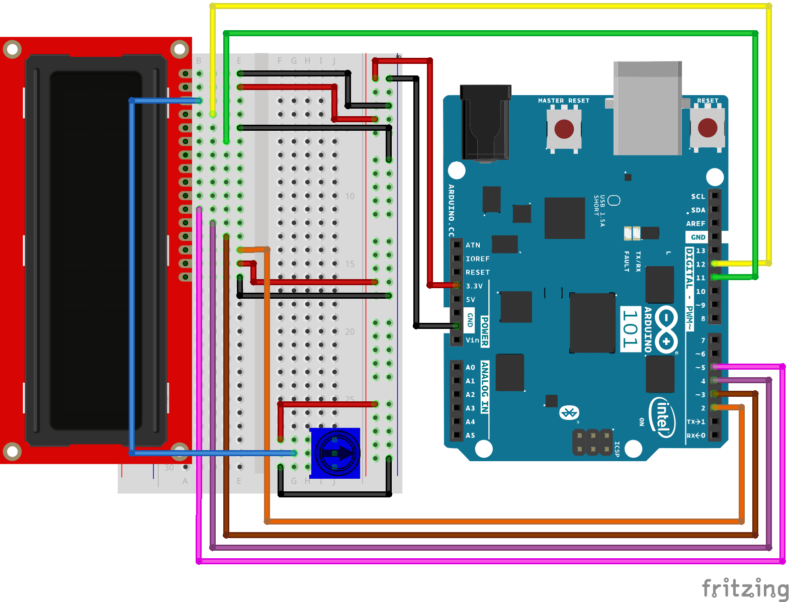
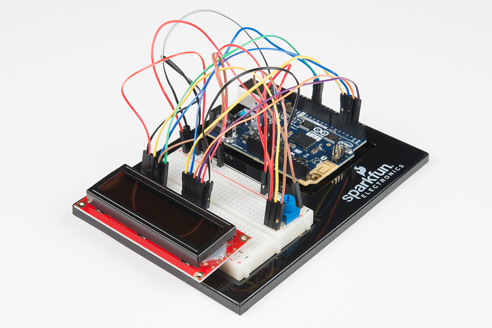
是否准备好开始对每个部件进行接线?请查看下面的接线图以了解如何连接每个部件。
| 极化组件 | 请特别注意组件用于指示如何在实验电路板上放置它的标记。极化组件只能按一个方向连接到电路。 |
实验的接线图
打开草图
在计算机上打开 Arduino IDE 软件。采用 Arduino 语言进行编码可控制电路。通过访问您先前下载并置于“示例”文件夹中的“101 SIK 指南代码”,来打开用于电路 20 的代码。
要打开该代码,请转到:文件 > 示例 > 101 SIK 指南代码 > Circuit_20
还可以将以下代码复制并粘贴到 Arduino IDE 中。点击“上传”,然后查看发生的情况!
language:cpp
/*
SparkFun Inventor's Kit
Example sketch 20

DISPLAYING THE DATE AND TIME

This sketch reads the RTC data and prints it on the LCD screen

This sketch was written by SparkFun Electronics,
with lots of help from the Arduino community.
This code is completely free for any use.
Visit http://learn.sparkfun.com/products/2 for SIK information.
Visit http://www.arduino.cc to learn more about Arduino.
*/

//include the CurieTime Library
#include
#include

//instantiate the lcd
LiquidCrystal lcd(12, 11, 5, 4, 3, 2);

void setup()
{
  //start lcd at 16 x 2
  lcd.begin(16, 2);

  //clear the lcd
  lcd.clear();

  //set time to 1:35:24 on April 4th, 2016\. Please change to your time / date
  setTime(1, 35, 24, 4, 10, 2016);
}

void loop()
{
 //create a character array of 16 characters for the time
 char clockTime[16];
 //use sprintf to create a time string of the hour, minte and seconds
 sprintf(clockTime, "    %2d:%2d:%2d    ", hour(), minute(), second());

 //create a character array of 15 characters for the date
 char dateTime[16];
 //use sprintf to create a date string from month, day and year
 sprintf(dateTime, "   %2d/%2d/%4d   ", month(), day(), year());

 //set cursor to column 0, row 0
 lcd.setCursor(0, 0);
 //print the date string over lcd
 lcd.print(dateTime);
 //set cursor to column 0, row 1
 lcd.setCursor(0, 1);
 //print the time string over lcd
 lcd.print(clockTime);
}
要注意的代码
setTime(1,35,00,4,10,2016);
101 开发板上的 RTC 在加电时必须进行设置。可使用 setTime() 函数执行此操作。需要按小时、分、秒、月、天、年的顺序向 setTime() 传递 6 个参数。如果 101 开发板由于某种原因而断电,则您必须使用此函数重置它。
sprintf(dateTime, " %2d/%2d/%4d ", month(), day(), year()); sprintf() 是字符串构建函数。这是通过接收数据并将它们置于字符数组(这在 Arduino 中基本上就是字符串)中来构建字符串的简单方式。%2d 和 %4d 中有趣的一点在于数据在插入时指定了数字位数,因此 %4d 是 4 位数。最后将要插入到字符串中的数据作为参数进行传递。在此例中是 month()、day() 和 year()。
应看到的情况
代码完全上传之后,您应看到 LCD 屏幕上显示两行文本。第一行应是日期(只应每天更改一次),第二行应是当前时间(应看到它在持续计数)。如果不是这样,请查看下面的“故障诊断”部分。
故障诊断
屏幕空白或完全亮起
通过旋转电位计来调整对比度。如果未进行正确调整,则您无法阅读文本。
完全不运行
仔细检查代码,特别是您是否包含了 LCD 库。
未显示正确时间
仔细检查代码。您可能必须更新 setTime() 函数。