SIK Experiment Guide for the Arduino 101/Genuino 101 Board (Chinese)
This Tutorial is Retired!
This tutorial covers concepts or technologies that are no longer current. It's still here for you to read and enjoy, but may not be as useful as our newest tutorials.
 D___Run___
 实验 16:使用移位寄存器
简介
现在我们将步入原始 IC(集成电路)的世界。在本实验中,您将了解有关使用移位寄存器的所有信息。移位寄存器会为 101 开发板提供额外八个输出(仅使用板上的三个针脚)。对于本实验,您将练习使用移位寄存器控制八个 LED。是的 -- 比实验 4 还要多两个 LED!
所需部件
您需要以下部件:
- 1x 实验电路板
- 1x Arduino 101 或 Genuino 101 开发板
- 8x LED
- 8x 330Ω 电阻
- 1x 移位寄存器 8 位 - 74HC595
- 19x 跳线
没有 SIK?
如果您要执行本实验,但又没有 SIK,那么我们建议您使用这些部件:


您还需要一个 Arduino 101 或 Genuino 101 开发板。

Arduino 101
DEV-13787
Genuino 101
DEV-13984推荐阅读
继续进行本实验之前,我们建议您熟悉以下教程中的概念:
移位寄存器简介
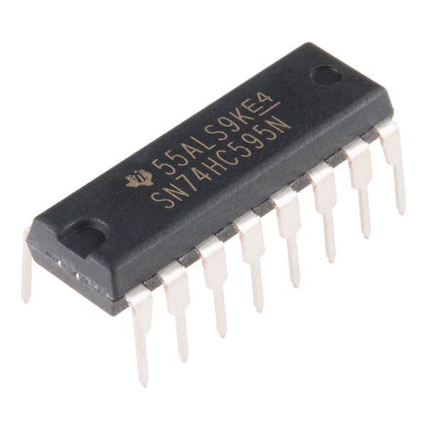
移位寄存器是一种集成电路 (IC)。IC 是由流行且常用的电路组成的微型塑料密封包。IC 充当单个组件,可执行特定作业功能,简化了过去曾经耗费大量时间和空间的电路设计。
移位寄存器本质上使您可以控制最多八个输出,同时仅使用 101 板上的三个针脚。与实验 4(在其中将六个针脚用于六个单独输出)相比,它使您可以通过更少的针脚控制更多的输出。
可这样理解:进入移位寄存器的数据类似于一列具有八个不同车厢的火车。如果车厢装满货物,则它表示的数据是 1。如果火车车厢为空,则它表示的数据是 0。当整列火车都进入移位寄存器时,它会分解,每个车厢都位于自己的轨道上。这些轨道可以转换为移位寄存器的八个输出针脚。如果车厢已满 (1),则它所处的针脚会上拉为 HIGH;如果车厢为空 (0),则针脚会下拉为 LOW。如果您在火车进入移位寄存器之后不断发送火车,则可以使 LED 呈现动态或控制类似于 7 段显示器的设备来倒计数,甚至是在不同时间转动的大量马达。只需向移位寄存器发送具有不同 1 和 0 模式的火车,即可实现所有这些目标。
如需了解有关火车移位寄存器的更多信息,请查看我们的移位寄存器教程。
硬件接线
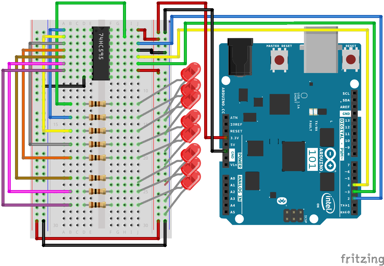
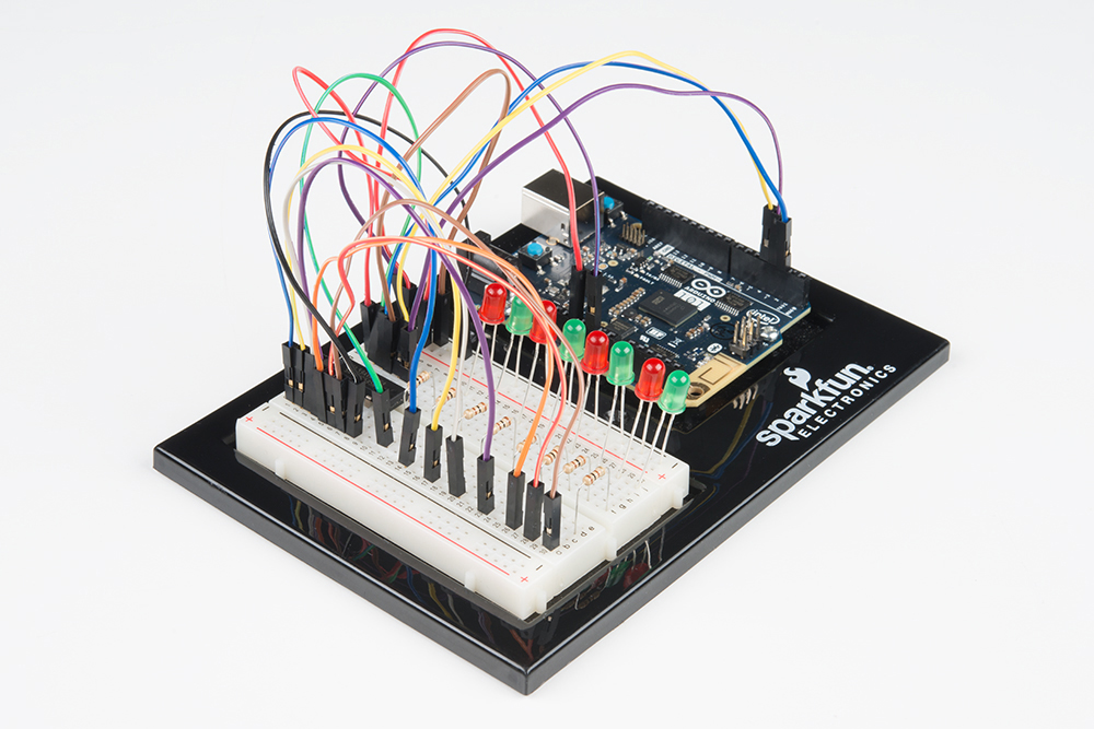
是否准备好开始对每个部件进行接线?请查看下面的接线图以了解如何连接每个部件。
| 极化组件 | 请特别注意组件用于指示如何在实验电路板上放置它的标记。极化组件只能按一个方向连接到电路。 |
实验的接线图
打开草图
在计算机上打开 Arduino IDE 软件。采用 Arduino 语言进行编码可控制电路。通过访问您先前下载并置于“示例”文件夹中的“101 SIK 指南代码”,来打开用于电路 16 的代码。
要打开该代码,请转到:文件 > 示例 > 101 SIK 指南代码 > Circuit_16
还可以将以下代码复制并粘贴到 Arduino IDE 中。点击“上传”,然后查看发生的情况!
language:cpp
/*
SparkFun Inventor's Kit
Example sketch 16

SHIFT REGISTER

  Use a shift register to turn three pins into eight (or more!)
  outputs

This sketch was written by SparkFun Electronics,
with lots of help from the Arduino community.
This code is completely free for any use.
Visit http://learn.sparkfun.com/products/2 for SIK information.
Visit http://www.arduino.cc to learn more about Arduino.
*/

// Pin definitions:
// The 74HC595 uses a type of serial connection called SPI
// (Serial Peripheral Interface) that requires three pins:

int datapin = 2;
int clockpin = 3;
int latchpin = 4;

// We'll also declare a global variable for the data we're
// sending to the shift register:

byte data = 0;

void setup()
{
  // Set the three SPI pins to be outputs:

  pinMode(datapin, OUTPUT);
  pinMode(clockpin, OUTPUT);
  pinMode(latchpin, OUTPUT);
}

void loop()
{
  // We're going to use the same functions we played with back
  // in circuit 04, "Multiple LEDs," we've just replaced
  // digitalWrite() with a new function called shiftWrite()
  // (see below). We also have a new function that demonstrates
  // binary counting.

  // To try the different functions below, uncomment the one
  // you want to run, and comment out the remaining ones to
  // disable them from running.

  oneAfterAnother();      // All on, all off

  //oneOnAtATime();       // Scroll down the line

  //pingPong();           // Like above, but back and forth

  //randomLED();          // Blink random LEDs

  //marquee();

  //binaryCount();        // Bit patterns from 0 to 255
}

void shiftWrite(int desiredPin, boolean desiredState)

// This function lets you make the shift register outputs
// HIGH or LOW in exactly the same way that you use digitalWrite().

// Like digitalWrite(), this function takes two parameters:

//    "desiredPin" is the shift register output pin
//    you want to affect (0-7)

//    "desiredState" is whether you want that output
//    to be HIGH or LOW

// Inside the Arduino, numbers are stored as arrays of "bits,"
// each of which is a single 1 or 0 value. Because a "byte" type
// is also eight bits, we'll use a byte (which we named "data"
// at the top of this sketch) to send data to the shift register.
// If a bit in the byte is "1," the output will be HIGH. If the bit
// is "0," the output will be LOW.

// To turn the individual bits in "data" on and off, we'll use
// a new Arduino commands called bitWrite(), which can make
// individual bits in a number 1 or 0.
{
  // First we'll alter the global variable "data," changing the
  // desired bit to 1 or 0:

  bitWrite(data,desiredPin,desiredState);

  // Now we'll actually send that data to the shift register.
  // The shiftOut() function does all the hard work of
  // manipulating the data and clock pins to move the data
  // into the shift register:

  shiftOut(datapin, clockpin, MSBFIRST, data);

  // Once the data is in the shift register, we still need to
  // make it appear at the outputs. We'll toggle the state of
  // the latchPin, which will signal the shift register to "latch"
  // the data to the outputs. (Latch activates on the high-to
  // -low transition).

  digitalWrite(latchpin, HIGH);
  digitalWrite(latchpin, LOW);
}

/*
oneAfterAnother()

This function will light one LED, delay for delayTime, then light
the next LED, and repeat until all the LEDs are on. It will then
turn them off in the reverse order.
*/

void oneAfterAnother()
{
  int index;
  int delayTime = 100; // Time (milliseconds) to pause between LEDs
                       // Make this smaller for faster switching

  // Turn all the LEDs on:

  // This for() loop will step index from 0 to 7
  // (putting "++" after a variable means add one to it)
  // and will then use digitalWrite() to turn that LED on.

  for(index = 0; index <= 7; index++)
  {
    shiftWrite(index, HIGH);
    delay(delayTime);
  }

  // Turn all the LEDs off:

  // This for() loop will step index from 7 to 0
  // (putting "--" after a variable means subtract one from it)
  // and will then use digitalWrite() to turn that LED off.

  for(index = 7; index >= 0; index--)
  {
    shiftWrite(index, LOW);
    delay(delayTime);
  }
}

/*
oneOnAtATime()

This function will step through the LEDs, lighting one at at time.
*/

void oneOnAtATime()
{
  int index;
  int delayTime = 100; // Time (milliseconds) to pause between LEDs
                       // Make this smaller for faster switching

  // step through the LEDs, from 0 to 7

  for(index = 0; index <= 7; index++)
  {
    shiftWrite(index, HIGH);    // turn LED on
    delay(delayTime);       // pause to slow down the sequence
    shiftWrite(index, LOW); // turn LED off
  }
}

/*
pingPong()

This function will step through the LEDs, lighting one at at time,
in both directions.
*/

void pingPong()
{
  int index;
  int delayTime = 100; // time (milliseconds) to pause between LEDs
                       // make this smaller for faster switching

  // step through the LEDs, from 0 to 7

  for(index = 0; index <= 7; index++)
  {
    shiftWrite(index, HIGH);    // turn LED on
    delay(delayTime);       // pause to slow down the sequence
    shiftWrite(index, LOW); // turn LED off
  }

  // step through the LEDs, from 7 to 0

  for(index = 7; index >= 0; index--)
  {
    shiftWrite(index, HIGH);    // turn LED on
    delay(delayTime);       // pause to slow down the sequence
    shiftWrite(index, LOW); // turn LED off
  }
}

/*
randomLED()

This function will turn on random LEDs. Can you modify it so it
also lights them for random times?
*/

void randomLED()
{
  int index;
  int delayTime = 100; // time (milliseconds) to pause between LEDs
                       // make this smaller for faster switching

  // The random() function will return a semi-random number each
  // time it is called. See http://arduino.cc/en/Reference/Random
  // for tips on how to make random() more random.

  index = random(8);    // pick a random number between 0 and 7

  shiftWrite(index, HIGH);  // turn LED on
  delay(delayTime);     // pause to slow down the sequence
  shiftWrite(index, LOW);   // turn LED off
}

/*
marquee()

This function will mimic "chase lights" like those around signs.
*/

void marquee()
{
  int index;
  int delayTime = 200; // Time (milliseconds) to pause between LEDs
                       // Make this smaller for faster switching

  // Step through the first four LEDs
  // (We'll light up one in the lower 4 and one in the upper 4)

  for(index = 0; index <= 3; index++)
  {
    shiftWrite(index, HIGH);    // Turn a LED on
    shiftWrite(index+4, HIGH);  // Skip four, and turn that LED on
    delay(delayTime);       // Pause to slow down the sequence
    shiftWrite(index, LOW); // Turn both LEDs off
    shiftWrite(index+4, LOW);
  }
}

/*
binaryCount()

Numbers are stored internally in the Arduino as arrays of "bits,"
each of which is a 1 or 0\. Just like the base-10 numbers we use
every day, The position of the bit affects the magnitude of its
contribution to the total number:

Bit position   Contribution
0              1
1              2
2              4
3              8
4              16
5              32
6              64
7              128

To build any number from 0 to 255 from the above 8 bits, just
select the contributions you need to make. The bits will then be
1 if you use that contribution, and 0 if you don't.

This function will increment the "data" variable from 0 to 255
and repeat. When we send this value to the shift register and LEDs,
you can see the on-off pattern of the eight bits that make up the
byte. See http://www.arduino.cc/playground/Code/BitMath for more
information on binary numbers.
*/

void binaryCount()
{
  int delayTime = 1000; // time (milliseconds) to pause between LEDs
                        // make this smaller for faster switching

  // Send the data byte to the shift register:

  shiftOut(datapin, clockpin, MSBFIRST, data);

  // Toggle the latch pin to make the data appear at the outputs:

  digitalWrite(latchpin, HIGH);
  digitalWrite(latchpin, LOW);

  // Add one to data, and repeat!
  // (Because a byte type can only store numbers from 0 to 255,
  // if we add more than that, it will "roll around" back to 0
  // and start over).

  data++;

  // Delay so you can see what's going on:

  delay(delayTime);
}
要注意的代码
shiftOut(datapin, clockpin, MSBFIRST, data);
您将使用 SPI 与移位寄存器(和许多其他部件)进行通信。此接口使用一个数据线和单独的时钟线,它们相互配合,以高速将数据移入或移出 101 开发板。MSBFIRST 参数指定发送各个位型的顺序;在此例中,我们将首先发送最高有效位型。
bitWrite(data, desiredPin, desiredState);
位型是计算机中的最小可能内存片段;每个位型都可以存储“1”或“0”。较大数字存储为位型数组。有时我们要直接操作这些位型;例如,现在当我们向移位寄存器发送八个位型,并且我们要使它们为 1 或 0 以打开或关闭 LED 时。Arduino 具有几个使此操作易于执行的命令(如 bitWrite())。
应看到的情况
与实验 4 类似,您应看到 LED 亮起(但是这次您是使用移位寄存器)。如果它们未亮起,请确保正确装配了电路以及验证了代码并将它上传到开发板。请查看“故障诊断”部分。
故障诊断
Arduino 的电源 LED 熄灭
这种情况在我们遇到过好几次了。当芯片插反时,会发生这种情况。如果您进行了快速修复,则不会有任何组件损坏。
未完全运行
很抱歉听上去像是老生常谈,不过可能就是如同跨接导线这样简单的错误而造成的。