SIK Experiment Guide for the Arduino 101/Genuino 101 Board (Chinese)
This Tutorial is Retired!
This tutorial covers concepts or technologies that are no longer current. It's still here for you to read and enjoy, but may not be as useful as our newest tutorials.
 D___Run___
 简介:Arduino/Genuino SparkFun Inventor's Kit
此《SparkFun Inventor's Kit 实验指南》可指导您使用基于英特尔® Curie 的 Arduino 101® 或 Genuino 101® 开发板探索入门级嵌入式电子设备。此指南包含探索适用于 Arduino 101 的 SparkFun Inventor's Kit 的 21 个电路所需的所有信息。此指南围绕一个核心理念 -- 任何人都可以(并且应该)使用尖端电子设备。
当您完成此指南的学习之后,您将了解如何开始创建自己的项目和实验,从构建机器人和游戏控制器到 IoT(物联网)和数据记录,世界将在您的掌控之中。现在不再废话 -- 让我们开始进行发明创造!
包含的材料
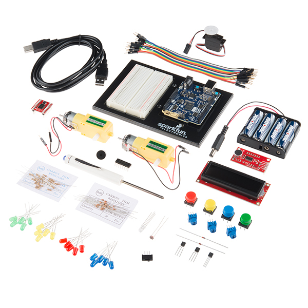
下面是适用于 Arduino 101/Genuino 101 开发板的 SparkFun Inventor's Kit (101 SIK) 的所有部件:
- Arduino 101/Genuino 101 -- Arduino 101 或 Genuino 101 开发板。
- Arduino 和实验电路板固定架 -- 一个很棒的固定架,用于 Arduino 101/Genuino 101 开发板和实验电路板。
- 实验电路板 -- 十分适用于制作 Arduino 的电路和连接。
- 便携盒 -- 方便地随处携带套件。
- SparkFun 微型螺丝刀 -- 用于帮助您使用螺钉将 RedBoard 安装到固定架上。
- 3.3V 16x2 黑底白字 LCD(带接头) -- 这是基本的 16 字符 2 行显示器,具有精美的黑色背景和白色字符,运行电压是 3.3V。
- 74HC595 移位寄存器 -- 简单的移位寄存器 IC。记录数据并进行锁定以释放 RedBoard 上的 IO 针脚。
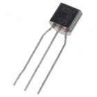
- NPN 晶体管 -- 此小型晶体管可以用于帮助驱动大型负载,或是放大或切换应用。
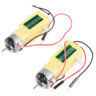
- 业余级齿轮马达组 -- 一组业余级马达,其齿轮箱设置为 120 RPM。
- 小型伺服马达 -- 这是一个可满足所有机电需求的简单、低成本、高质量伺服马达。
- SPDT 开关 -- 这是一个高质量单刀 - 双掷 (SPDT) 开关,十分适合于实验电路板。
- TMP36 温度传感器 -- 一个用于检测温度变化的传感器。
- ** USB A 到 B 电缆** -- 这根 6' 电缆在主机端提供 USB-A 连接器,在设备端提供标准 B 连接器。
- 插头到插头跳线 -- 这些是高质量导线,使您可以将 Arduino 上的插孔接头连接到组件和实验电路板。
- 光电管 -- 一个用于检测环境光线的传感器。十分适合于检测何时打开抽屉或何时夜间临近。
- 三色 LED -- 因为每个人都喜欢闪亮亮的东西。
- 红色、蓝色、黄色和绿色 LED -- 发光二极管可制作很棒的常规指示灯。
- 红色、蓝色、黄色和绿色触觉按钮 -- 不同的彩色按钮会让您欣喜若狂。
- 10K 电位器 -- 也称为可变电阻,这是常用于控制音量和对比度的设备,可形成很好的常规用户控制输入。
- 压电式蜂鸣器 -- 用于形成声音和播放歌曲。
- 100 欧姆电阻 -- 用于 3.3V LED 的不错限流电阻,并且是强大的上拉电阻。
- 10K 欧姆电阻 -- 这些可用作不错的上拉电阻、下拉电阻和限流器。
- SparkFun 马达驱动器 -- 这款精致的小型板十分适合于控制最多两个单独马达的速度和方向。
- SparkFun 声音探测器板 -- 一个麦克风分支板,具有三个输出:原始音频、封包和 GATE。此板十分适合于基于声音的简单项目。
实验列表
下面是您将使用此 101 SIK 实验指南完成的实验的列表。或者,您也可以使用右侧按钮四处导航。
- 实验 1:使 LED 闪烁
- 实验 2:读取电位计
- 实验 3:驱动 RGB LED
- 实验 4:驱动多个 LED
- 实验 5:读取按下按钮操作
- 实验 6:读取 SPDT 开关
- 实验 7:读取光敏电阻
- 实验 8:使用 RGB 混合颜色
- 实验 9:读取温度传感器
- 实验 10:驱动伺服马达
- 实验 11:使用晶体管
- 实验 12:使用马达驱动器
- 实验 13:具有输入的马达驱动器
- 实验 14:使用压电式蜂鸣器
- 实验 15:使用声音探测器板
- 实验 16:使用移位寄存器
- 实验 17:使用 LCD
- 实验 18:读取板载重力感应器
- 实验 19:点击检测
- 实验 20:使用板载实时时钟
- 实验 21:使用板载低能量蓝牙
推荐阅读
继续查看此指南之前,我们建议您熟悉一下以下教程中的概念:
- 电压、电流、电阻和欧姆定律 - 电子和电气工程中的最基本概念。请确保非常熟悉这些概念,因为它们将贯穿用于您的整个电子设备探索活动过程。
- 什么是电路?- 在此指南中,我们将构建各种电路。了解电路的含义对于了解 Inventor's Kit 至关重要。
- 如何使用实验电路板 -- 首次使用实验电路板?请查看此教程!它将帮助您了解实验电路板为何十分适用于原型设计以及如何使用。
开放源代码!
在 SparkFun,我们的工程师和教育工作者会在很长一段时间内不断改进此套件并提出新实验。我们要感谢 Oomlout 从最初多年前整理 Arduino 套件材料开始以来所付出的努力。Oomlout 和 SparkFun 版本按照 Creative Commons Attribution Share-Alike 3.0 Unported License 获得许可。
要查看此许可证的副本,请访问此链接,或写信给以下地址:Creative Commons, 171 Second Street, Suite 300, San Francisco, CA 94105, USA。
什么是 101?

Arduino 101 是一款学习和开发主板,它具有英特尔 Curie 模块的高性能和低功耗特性,同时兼具 Arduino 的简洁性,而且价格便宜。这款开发主板的强大版型和外围设备支持列表与 UNO 相同,并添加了板载低能量蓝牙功能以及一个 6 轴重力感应器和陀螺仪(称为惯性测量单元 (IMU)),可帮助您在联网环境中轻松开展创新活动。
英特尔 Curie 模块包含两个小型内核,一个 x86 (Quark) 和一个 32 位 ARC 体系结构内核,其时钟都是 32MHz。英特尔工具链可通过最佳方式在两个内核间编译 Arduino 草图,以完成要求最苛刻的任务。Arduino 101 开发板带有 14 个数字输入/输出针脚(其中 4 个可以用作 PWM 输出)、6 个模拟输入、1 个用于串行通信和草图上传的 USB 连接器、1 个电源插座、1 个具有 SPI 信号和 I2C 专用针脚的 ICSP 接头。该开发板运行电压和 I/O 是 3.3V,但是所有针脚都可防护 5V 过电压。
下载并安装 Arduino 软件
下载 Arduino IDE
要准备并运行 101 开发板,您需要先从 www.arduino.cc 下载最新版本的 Arduino 软件(免费且开发源代码!)。此软件称为 Arduino IDE,能让您对开发板进行编程以完全按照自己的想法执行操作。它类似于用于编写程序的字处理器。使用联网的计算机,打开您常用的浏览器,然后转到 Arduino 下载页面。
查看我们的安装 Arduino IDE 教程以详细了解如何在计算机上安装 Arduino IDE。
将开发板添加到 Arduino IDE
自 Arduino 版本 1.6.2 推出以来,Arduino 大大简化了对可以使用 Arduino IDE 编程的开发板进行添加和更新的操作。这可以通过开发板管理器进行。Arduino 101 不属于随 Arduino IDE 的原始下载附带的标准核心开发板集合,因此您必须通过开发板管理器添加它。
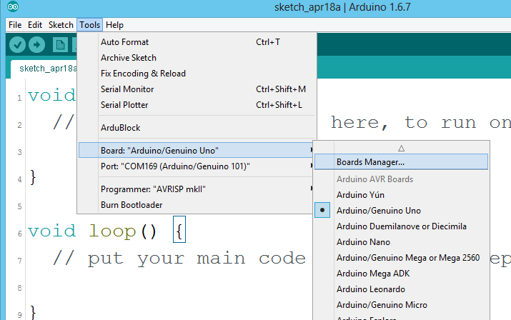
要访问开发板管理器,请打开 Arduino IDE。在顶部的下拉菜单中,选择工具 > 开发板 > 开发板管理器...。这会显示开发板管理器,如下所示。

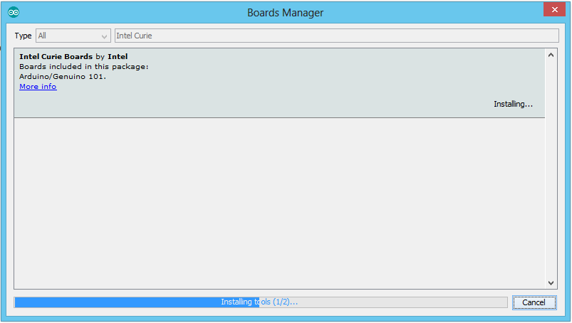
在开发板管理器中,搜索“英特尔 Curie”。这应显示一个选项,该选项此时是 101。选择此选项,然后单击“安装”。根据网络连接的速度,这可能需要花费几分钟。此过程是下载计算机需要用于开发板的驱动程序以及示例代码、库和开发板定义。系统会弹出几个对话框,请求您允许安装驱动程序并更改某些文件;继续进行并接受这些内容。
此过程完成之后,我们建议完全关闭 Arduino IDE,然后重新打开它。一旦它已打开并准备就绪,您便可以使用 USB 电缆将 101 开发板插入计算机。
将 101 开发板连接到计算机
使用 SparkFun Inventor's Kit (SIK) 中提供的 USB 电缆将 101 开发板插入计算机上的一个 USB 输入。
开始使用 Arduino IDE
现在,终于要打开 Arduino 软件了。系统会向您显示一个窗口,类似于下面这样:
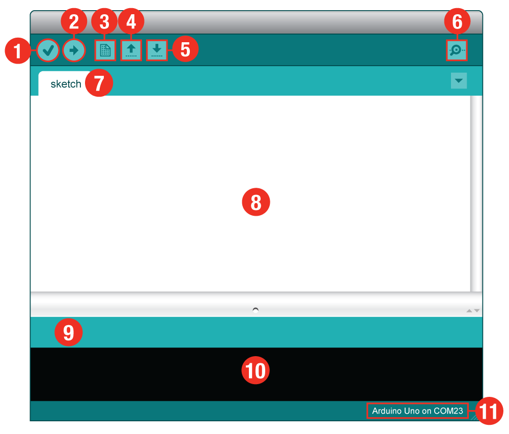
- 验证:编译并审批您的代码。它会捕获语法中的错误(如缺少分号或括号)。
- 上传:将您的代码发送到 101 开发板。
- 新建:此按钮会打开新代码窗口选项卡。
- 打开:此按钮会让您打开现有草图。
- 保存:这会保存当前活动草图。
- 串行监视器:这会打开一个窗口,其中显示 101 开发板所传输的任何串行信息。这对于调试非常有用。
- 草图名称:这会显示您当前所处理的草图的名称。
- 代码区域:这是在其中为草图编写代码的区域。
- 消息区域:IDE 在此位置向您告知代码中是否存在错误。
- 文本控制台:文本控制台显示完整错误消息。进行调试时,文本控制台非常有用。
- 开发板和串行端口:向您显示开发板和串行端口选择。
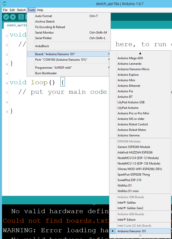
选择开发板:Arduino/Genuino 101
我们需要先进行一些调整,然后才能开始进入实验。此步骤需要向 Arduino IDE 告知在许多 Arduino 开发板中,我们具有哪些开发板。转到工具菜单。然后将鼠标悬停在开发板上方,确保选择了 Arduino/Genuino 101。
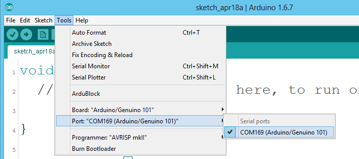
选择串行端口
接下来我们需要向 Arduino IDE 告知 101 开发板连接到计算机的哪个串行端口。再次转到工具,将鼠标悬停在端口上方,然后选择 101 开发板的串行端口。这会让 Arduino 101 出现在带括号的端口号旁。
Windows 用户:这可能是 COM3 或更高(COM1 和 COM2 通常保留用于硬件串行端口)。如果有多个 COM 端口可用,则 101 开发板可能是列表中编号最大的端口。要进行确定,还可以断开 101 开发板的连接,然后重新打开菜单;消失的条目应是 101 开发板。重新连接开发板并选择该串行端口。
Mac 用户:从工具中选择 101 开发板的串行设备,然后将鼠标悬停在端口上方。在 Mac 上,这应是包含 /dev/tty.usbmodem or /dev/tty.usbserial 的内容。
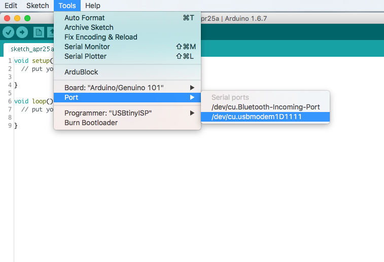
Linux 用户:请访问 Arduino 学习 Linux 部分,以了解有关 Linux 上的 Arduino 的更多信息。
下载 Arduino 代码
设置的完成已近在眼前!下载 SIK 指南代码。单击以下链接可下载该代码:
解压“101_SIK_Guide_Code”并将它复制到 Arduino 文件夹中的“示例”文件夹中。
Windows 用户:解压文件“101_SIK_Guide_Code”。它应位于浏览器的“下载”文件夹中。右键单击压缩文件夹并选择“解压”。将“SIK 指南代码”文件夹复制到名为“示例”的 Arduino 文件夹中。
Mac 用户:解压文件“101_SIK_Guide_Code”。它应位于浏览器的“下载”文件夹中。右键单击压缩文件夹并解压。在应用程序文件夹中查找“Arduino”。右键单击(ctrl + 单击)“Arduino”。选择“显示软件包内容”。然后,单击浏览文件夹内容 > 资源 > Java > 示例。将“101 SIK 指南代码”文件夹复制到名为“示例”的 Arduino 文件夹中。
实验 1:使 LED 闪烁
简介
LED 是小型而功能强大的灯,可用于许多不同应用。开始时,我们将设法使一个 LED(微控制器的 Hello World)闪烁。没错 -- 这如同开灯和关灯一样简单。这可能看上去没有太多意义,不过建立这一重要基准线会随着我们开展更复杂的实验而为您打下坚实的基础。
所需部件
您需要以下部件:
- 1x 实验电路板
- 1x Arduino 101 或 Genuino 101 开发板
- 1x LED
- 1x 100Ω 电阻
- 3x 跳线
没有 101 SIK?
如果您要执行本实验,但又没有 101 SIK,那么我们建议您使用这些部件:


您还需要一个 Arduino 101 或 Genuino 101 开发板。

Arduino 101
DEV-13787
Genuino 101
DEV-13984推荐阅读
继续进行本实验之前,我们建议您熟悉以下教程中的概念:
- 发光二极管 -- 了解有关 LED 的更多信息!
LED 简介
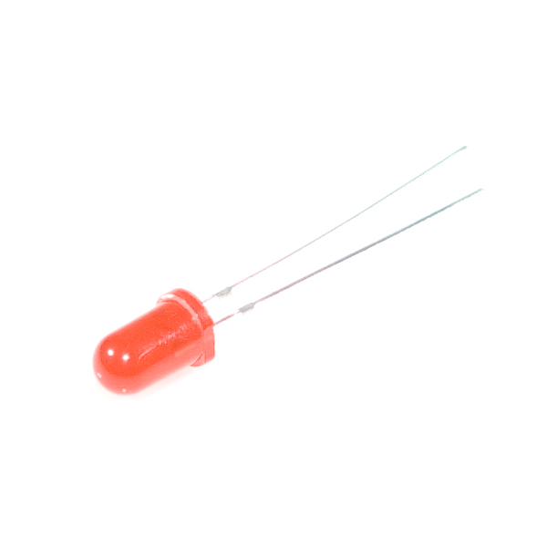
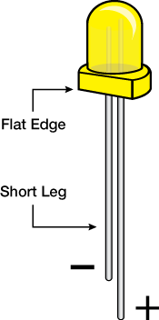
发光二极管 (LED) 仅允许电流按一个方向通过它。可将 LED 视为单行道。电流流过 LED 时,它会点亮!如果您查看一下 LED,便会注意到其引脚具有不同长度。长引脚(“阳极”)是电流进入 LED 的位置。此针脚应始终连接到电流源。短引脚(“阴极”)是电流出口。短引脚应始终连接到接地路径。
对于 LED 施加的电流量,LED 要求十分严苛。电流太大可能会导致 LED 烧坏。为了限制通过 LED 的电流量,我们将一个电阻与电源和 LED 的长引脚并联使用;这称为限流电阻。对于 101 开发板,应使用 100 欧姆电阻。正因为如此,我们在工具包中包含了一袋这样的电阻!
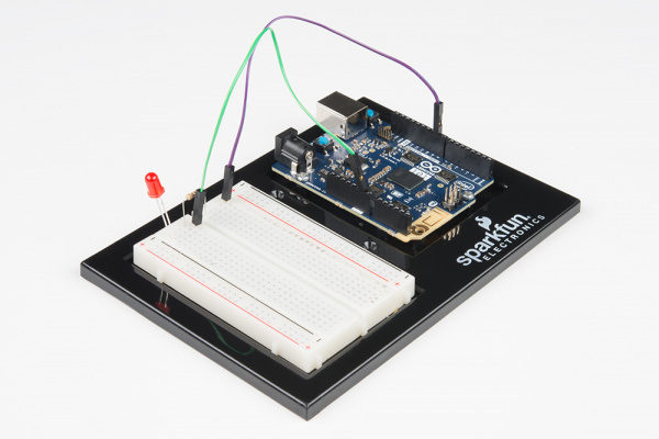
硬件接线
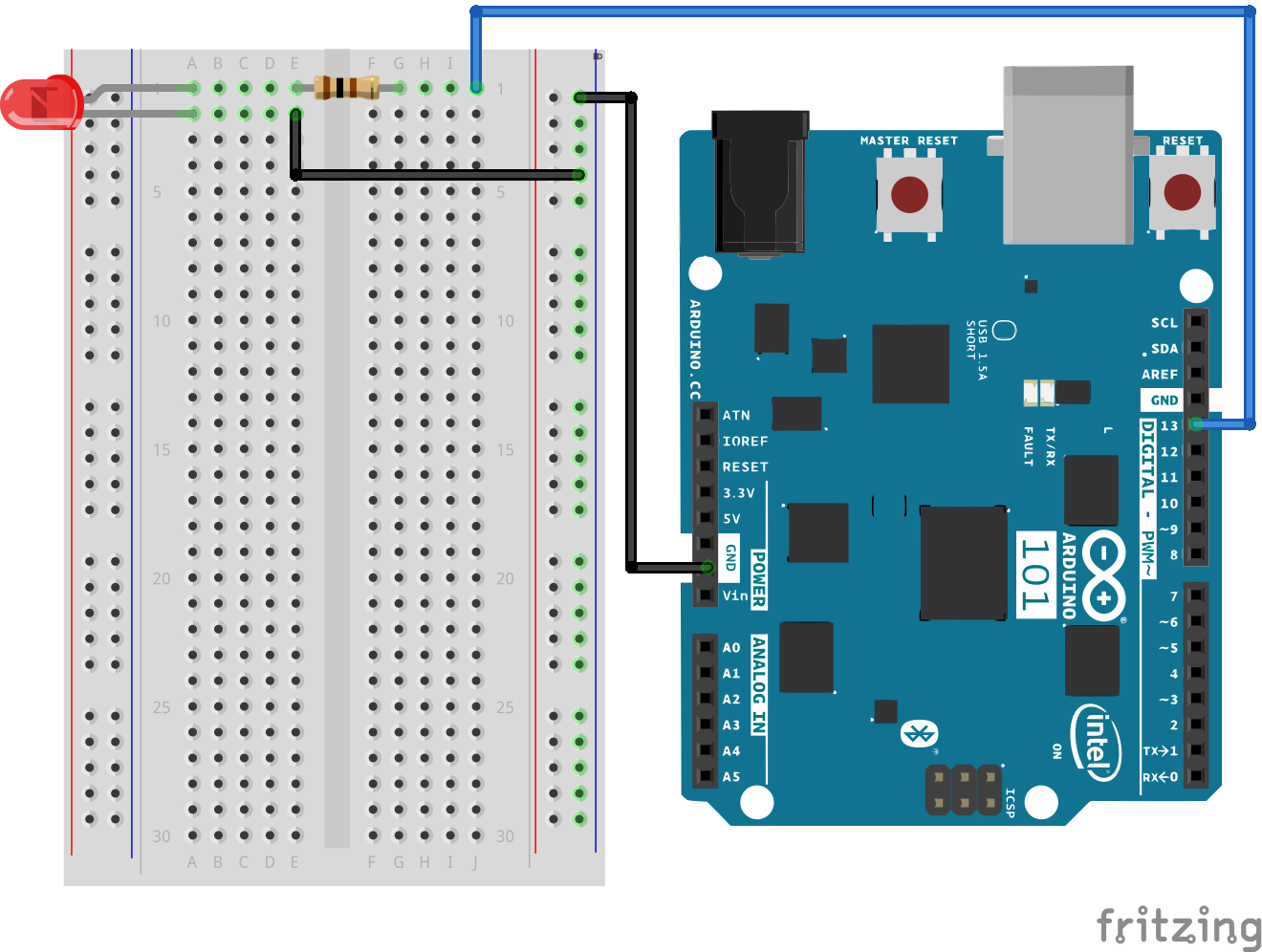
是否准备好开始对每个部件进行接线?请查看下面的接线图和接线表以了解如何连接每个部件。
| 极化组件 | 请特别注意组件用于指示如何在实验电路板上放置它的标记。极化组件只能按一个方向连接到电路。在下表中,极化组件使用黄色警告三角突出显示。 |
请注意:密切注意 LED。LED 的负极是短引脚,使用平边进行标记。
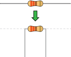
诸如电阻这类组件需要将其引脚弯曲成 90° 角,以便正确插入实验电路板插槽。您也可以将引脚切短以使它们更易于在实验电路板上使用。
实验的接线图
打开第一个草图
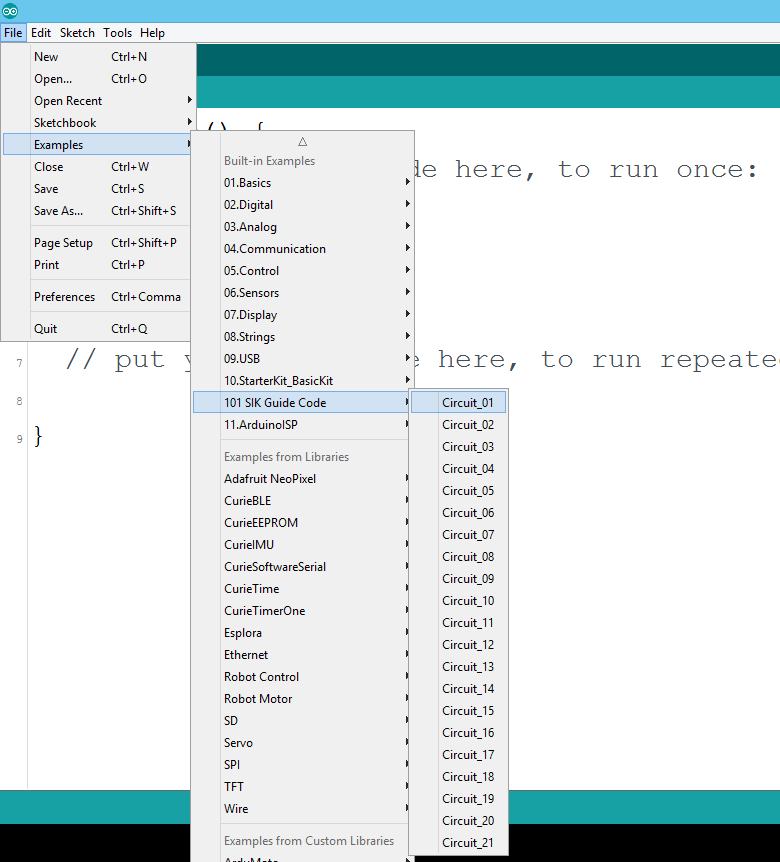
在计算机上打开 Arduino IDE 软件。采用 Arduino 语言进行编码可控制电路。通过访问您先前下载并置于“示例”文件夹中的“101 SIK 指南代码”,来打开用于电路 1 的代码。
要打开该代码,请转到:文件 > 示例 > 101 SIK 指南代码 > Circuit_01
还可以将以下代码复制并粘贴到 Arduino IDE 中。点击“上传”,然后查看发生的情况!
language:cpp
/*
SparkFun Inventor's Kit for the Arduino / Genuino 101
Example sketch 01

BLINKING AN LED

Turn an LED on for one second, off for one second,
and repeat forever.

This sketch was written by SparkFun Electronics,
with lots of help from the Arduino community.
This code is completely free for any use.
Visit http://learn.sparkfun.com/products/2 for SIK information.
Visit http://www.arduino.cc to learn about Arduino.
*/

//The setup function runs once upon your Arduino being powered or once upload is          //complete.

void setup()
{
  //set pin 13 to OUTPUT
  pinMode(13, OUTPUT);
}

//The loop function runs from the top down and repeats itself until you upload new        //code or power down your Arduino
void loop()
{
  //Turn pin 13 HIGH (ON).
  digitalWrite(13, HIGH);

  //wait 1000 milliseconds (1 second)
  delay(1000);

  //Turn pin 13, LOW (OFF)
  digitalWrite(13, LOW);

  //wait 1000 milliseconds
  delay(1000);
}
要注意的代码
pinMode(13, OUTPUT);
您需要先告知开发板是 INPUT 还是 OUTPUT,然后才能使用 101 开发板针脚中的一个。我们使用名为 pinMode() 的内置“函数”来执行此操作。
digitalWrite(13, HIGH);
将针脚用作 OUTPUT 时,您可以命令它成为 HIGH(输出 3.3 伏)或 LOW(输出 0 伏)。
应看到的情况
您应看到 LED 闪烁并熄灭。如果它没有这样,请确保正确装配了电路以及验证了代码并将它上传到开发板,或查看“故障诊断”部分。
故障诊断
程序未上传
有时会发生这种情况;最可能的原因是混淆了串行端口。可以在工具 > 串行端口 > 中更改此信息。
此外,如果您遇到超时错误或 IDE 找不到您的 101 开发板,请尝试按 101 开发板上的“主重置”按钮,等待大约 10 秒,然后尝试重新上传草图。
仍未成功
实验 2:读取电位计
简介
在此电路中,您将使用电位计。您将学习如何通过读取传感器并将它存储为变量,然后将它用作延迟时间,来使用电位计控制闪烁 LED 的时间。
所需部件
您需要以下部件:
- 1x 实验电路板
- 1x Arduino 101 或 Genuino 101 开发板
- 1x LED
- 1x 100Ω 电阻
- 7x 跳线
- 1x 电位计
没有 SIK?
如果您要执行本实验,但又没有 SIK,那么我们建议您使用这些部件:

您还需要一个 Arduino 101 或 Genuino 101 开发板。
Arduino 101
DEV-13787
Genuino 101
DEV-13984推荐阅读
继续进行本实验之前,我们建议您熟悉以下教程中的概念:
电位计简介
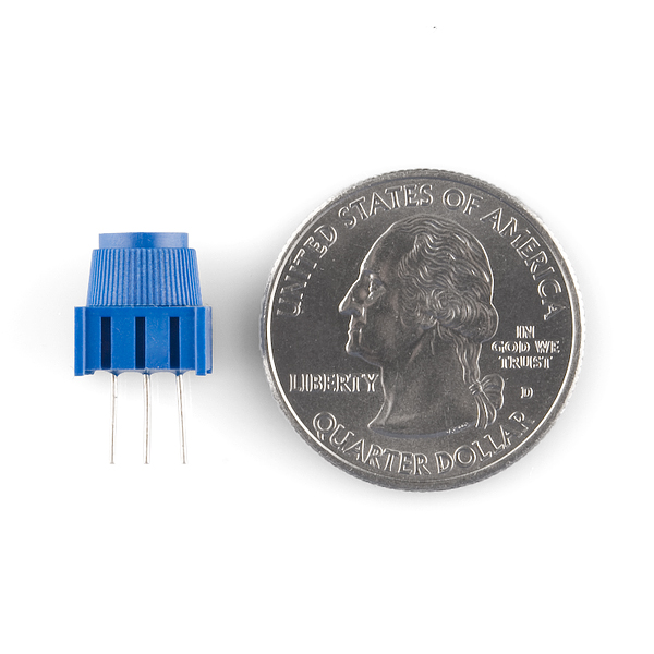
电位计是基于电阻的模拟传感器,可基于其旋钮的旋转来更改其内部电阻。电位计具有一个内部分压器,使您可以通过微控制器(101 开发板)读取中央针脚上的电压变化。要对电位计进行接线,请将两个外部针脚连接到电源电压(在此电路中是 3.3V)和接地。这两个针脚的连接位置并不重要,只要一个连接到电源,另一个连接到接地即可。中央针脚随后连接到模拟输入针脚,以便 101 开发板可以测量电压变化。扭动旋钮时,传感器读数会发生变化!
注:工具包中所含的电位计上具有三个标记,可帮助您确定针脚所插入到的实验电路板行。
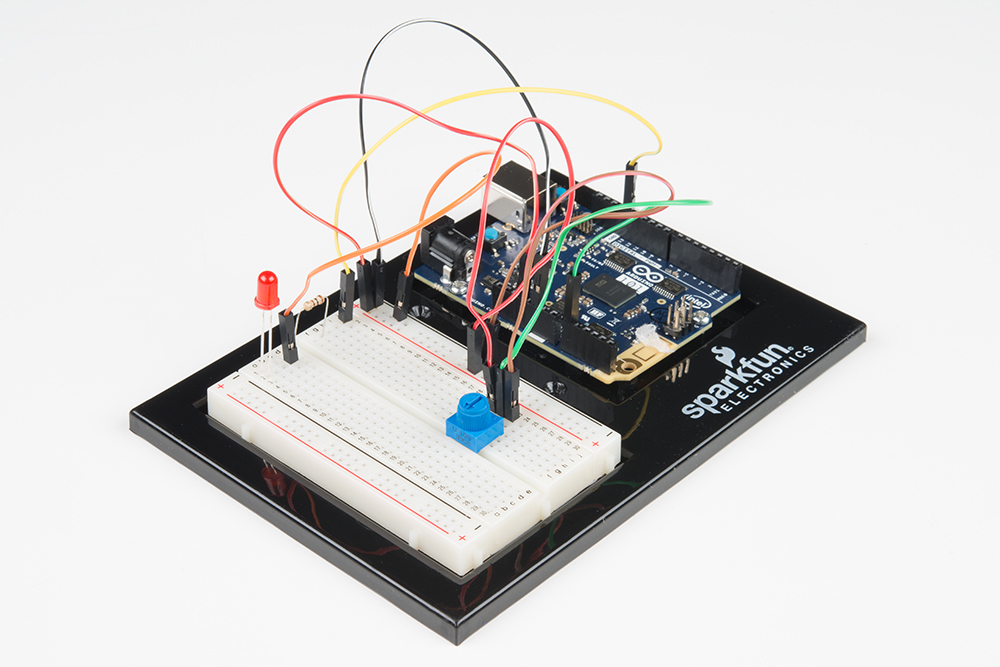
硬件接线
是否准备好开始对每个部件进行接线?请查看下面的接线图和接线表以了解如何连接每个部件。
| 极化组件 | 请特别注意组件用于指示如何在实验电路板上放置它的标记。极化组件只能按一个方向连接到电路。在表中,极化组件使用黄色警告三角突出显示。 |
实验的接线图

打开草图
在计算机上打开 Arduino IDE 软件。采用 Arduino 语言进行编码可控制电路。通过访问您先前下载并置于“示例”文件夹中的“101 SIK 指南代码”,来打开用于电路 2 的代码。
要打开该代码,请转到:文件 > 示例 > 101 SIK 指南代码 > Circuit_02
将以下代码复制并粘贴到 Arduino IDE 中。点击“上传”,然后查看发生的情况!
language:cpp
/* SparkFun Inventor's Kit
Example sketch 02

POTENTIOMETER

  Measure the position of a potentiometer and use it to
  control the blink rate of an LED. Turn the knob to make
  it blink faster or slower!

This sketch was written by SparkFun Electronics,
with lots of help from the Arduino community.
This code is completely free for any use.
Visit http://learn.sparkfun.com/products/2 for SIK information.
Visit http://www.arduino.cc to learn about Arduino.
*/

//Create global variables (variables that can be used anywhere in our sketch)

// Here we're creating a variable called "sensorPin" of type "int"
// and initializing it to have the value "0," which is the analog input pin the pot is     //conected to.
int sensorPin = 0;

// Variable for storing the pin number that the LED is connected to
int ledPin = 13;

// this function runs once when the sketch starts up
void setup()
{
  //set ledPin (13) as an OUTPUT
  pinMode(ledPin, OUTPUT);
}

// this function runs repeatedly after setup() finishes
void loop()
{

  //create a local variable (variable that can only be used inside of loop() to store       //a sensor value called sensorValue
  int sensorValue;

  //use the analogRead() function to read sensorPin and store the value in sensorValue
  sensorValue = analogRead(sensorPin);

  // Turn the LED on
  digitalWrite(ledPin, HIGH);

  delay(sensorValue);

  // Turn the LED off
  digitalWrite(ledPin, LOW);

 //delay for the value of sensorValue
  delay(sensorValue);

  //loop back to the top
}
要注意的代码
int sensorValue;
“变量”是可能在代码中更改的值的占位符。您必须先引入(或“声明”)变量,然后才能使用它们;此处您要声明一个名为 sensorValue 的变量,其类型为“int”(整数)。请记住,变量名称区分大小写!
sensorValue = analogRead(sensorPin);
使用 analogRead() 函数读取模拟针脚上的值。analogRead() 采用一个参数,即要使用的模拟针脚(“sensorPin”),并返回一个介于 0(0 伏)和 1023(3.3 伏)之间的数字(“sensorValue”)。
delay(sensorValue);
微控制器非常快,能够每秒运行数千行代码。为了减慢其速度以便我们可以查看它所执行的操作,我们通常在代码中插入延迟。delay() 以毫秒为单位进行计数;一秒等于 1000 毫秒。
应看到的情况
您应看到 LED 闪烁根据电位计而加快或减慢。如果它未运行,请确保正确装配了电路以及验证了代码并将它上传到开发板,或查看“故障诊断”部分。
故障诊断
偶发运行
这最可能是由于与电位计针脚之间的连接稍微有些接触不良。解决此问题的方法通常可以是按下电位计,或将电位计电路移动到实验电路板上的其他某个位置。
未运行
确保没有意外地将滑动片(中央针脚,即电位计中的电阻元件)连接到数字针脚 0 而不是模拟针脚 0(电源针脚下方的针脚行)。
LED 未亮起
LED 只能按一个方向运行。仔细检查连接。
实验 3:驱动 RGB LED
简介
您知道甚至比闪烁的 LED 更加有趣的东西么?使用一个 LED 更改颜色。在此电路中,您将学习如何使用 RGB LED 创建独一无二的颜色组合。根据每个二极管的亮度,几乎可以创造出任何颜色!
所需部件
您需要以下部件:
- 1x 实验电路板
- 1x Arduino 101 或 Genuino 101 开发板
- 1x 共阴极 RGB LED
- 3x 100Ω 电阻
- 6x 跳线
没有 101 SIK?
如果您要执行本实验,但又没有 SIK,那么我们建议您使用这些部件:
您还需要一个 Arduino 101 或 Genuino 101 开发板。
Arduino 101
DEV-13787
Genuino 101
DEV-13984红绿蓝 (RGB) LED 简介
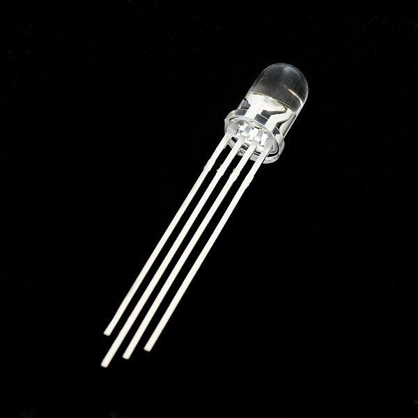
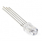
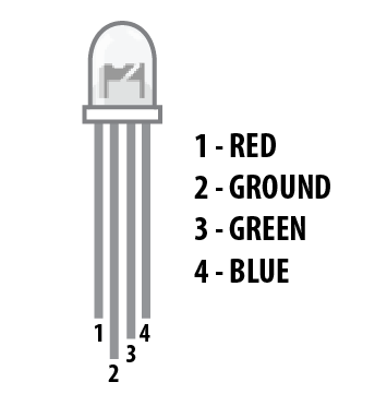
红绿蓝 (RGB) LED 是一体式的 3 个 LED。RGB 具有四个针脚,三个较短针脚中的每个针脚用于控制一种颜色:红色、绿色或蓝色。RGB 的较长针脚是通用接地针脚。您可以打开和关闭不同颜色以组合它们,从而创建自定义彩色 LED。例如,如果打开红色针脚和绿色针脚,则 RGB 会呈黄色亮起。
但是哪个针脚表示哪种颜色呢?拿起 RGB,以便最长针脚(通用接地)向左对齐,如下图所示。从最左侧开始,针脚分别是红色、接地、绿色和蓝色。
注:对 RGB 进行接线时,每个彩色针脚仍需要与您计划用于控制它的 101 开发板针脚并联一个限流电阻,如同任何标准 LED 一样。
硬件接线
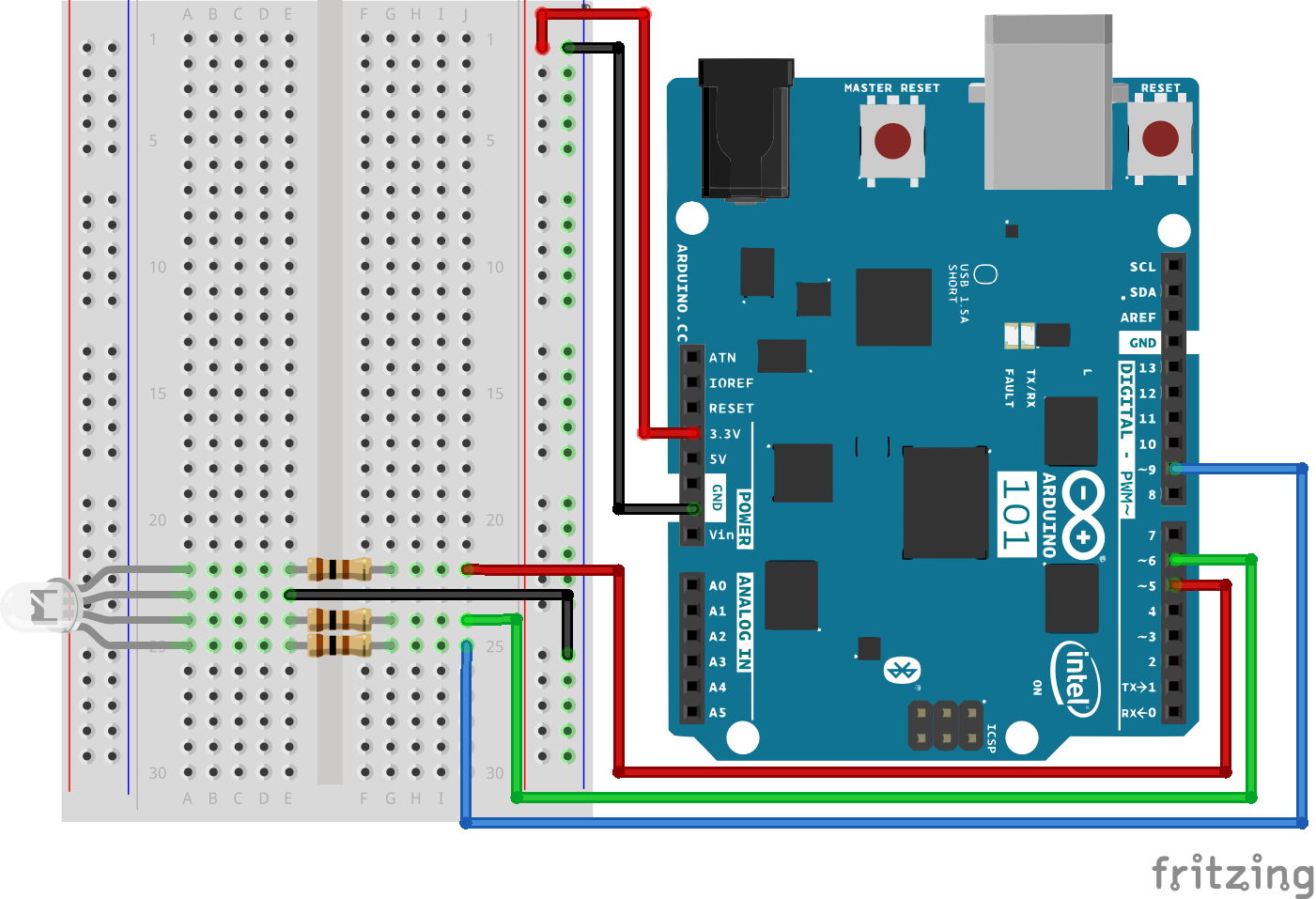
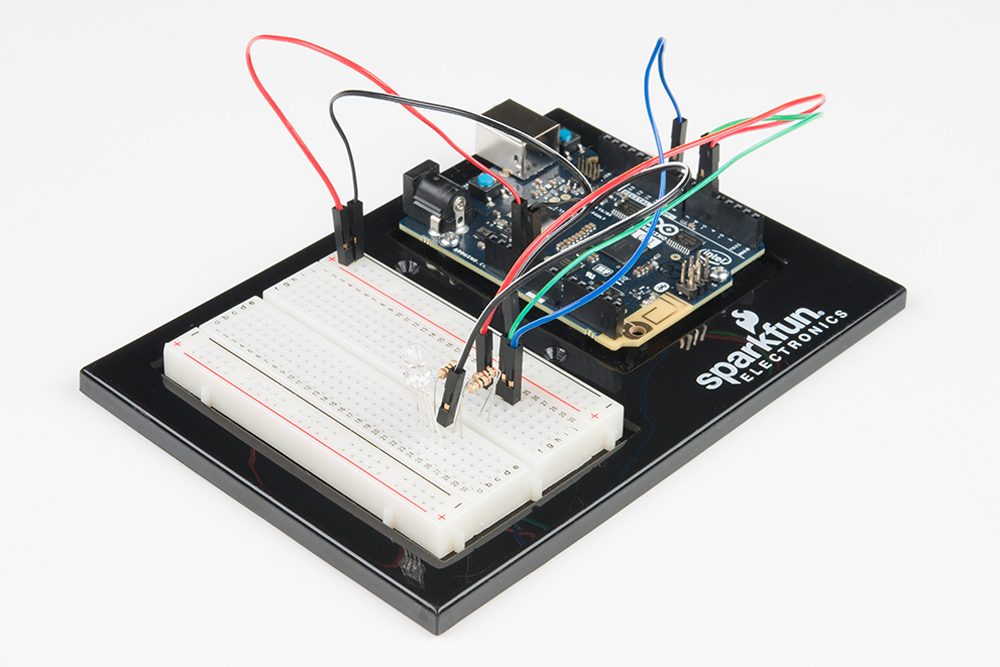
是否准备好开始对每个部件进行接线?请查看下面的接线图和接线表以了解如何连接每个部件。
| 极化组件 | 请特别注意组件用于指示如何在实验电路板上放置它的标记。极化组件只能按一个方向连接到电路。在下表中,极化组件使用黄色警告三角突出显示。 |
实验的接线图
打开草图
在计算机上打开 Arduino IDE 软件。采用 Arduino 语言进行编码可控制电路。通过访问您先前下载并置于“示例”文件夹中的“101 SIK 指南代码”,来打开用于电路 3 的代码。
要打开该代码,请转到:文件 > 示例 > 101 SIK 指南代码 > Circuit_03
还可以将以下代码复制并粘贴到 Arduino IDE 中。点击“上传”,然后查看发生的情况!
language:cpp
/*
SparkFun Inventor's Kit
Example sketch 03

RGB LED

Make an RGB LED display a rainbow of colors!

This sketch was written by SparkFun Electronics,
with lots of help from the Arduino community.
Visit http://learn.sparkfun.com/products/2 for SIK information.
Visit http://www.arduino.cc to learn about the Arduino.
*/

//create variables for pin numbers. We are making them constants here, because they       //never change.
const int RED_PIN = 5;
const int GREEN_PIN = 6;
const int BLUE_PIN = 9;

// How fast we plan to cycle through colors in milliseconds
int DISPLAY_TIME = 10;

void setup()
{
//set the three pin variables as outputs
pinMode(RED_PIN, OUTPUT);
pinMode(GREEN_PIN, OUTPUT);
pinMode(BLUE_PIN, OUTPUT);
}

void loop()
{
// We've written a custom function called mainColors() that steps
// through all eight of these colors. We're only "calling" the
// function here (telling it to run). The actual function code
// is further down in the sketch.
mainColors();

}

// Here's the mainColors() custom function we've written.
void mainColors()
{
// Off (all LEDs off):
digitalWrite(RED_PIN, LOW);
digitalWrite(GREEN_PIN, LOW);
digitalWrite(BLUE_PIN, LOW);

//wait 1 second
delay(1000);

// Red (turn just the red LED on):
digitalWrite(RED_PIN, HIGH);
digitalWrite(GREEN_PIN, LOW);
digitalWrite(BLUE_PIN, LOW);

//wait 1 seconds
delay(1000);

// Green (turn just the green LED on):
digitalWrite(RED_PIN, LOW);
digitalWrite(GREEN_PIN, HIGH);
digitalWrite(BLUE_PIN, LOW);

//wait 1 second
delay(1000);

// Blue (turn just the blue LED on):
digitalWrite(RED_PIN, LOW);
digitalWrite(GREEN_PIN, LOW);
digitalWrite(BLUE_PIN, HIGH);

//wait 1 second
delay(1000);

// Yellow (turn red and green on):
digitalWrite(RED_PIN, HIGH);
digitalWrite(GREEN_PIN, HIGH);
digitalWrite(BLUE_PIN, LOW);

//wait 1 second
delay(1000);

// Cyan (turn green and blue on):
digitalWrite(RED_PIN, LOW);
digitalWrite(GREEN_PIN, HIGH);
digitalWrite(BLUE_PIN, HIGH);

//wait 1 second
delay(1000);

// Purple (turn red and blue on):
digitalWrite(RED_PIN, HIGH);
digitalWrite(GREEN_PIN, LOW);
digitalWrite(BLUE_PIN, HIGH);

//wait 1 second
delay(1000);

// White (turn all the LEDs on):
digitalWrite(RED_PIN, HIGH);
digitalWrite(GREEN_PIN, HIGH);
digitalWrite(BLUE_PIN, HIGH);

//wait 1 second
delay(1000);
}
要注意的代码
language:cpp
for (x = 0; x < 768; x++)
{}
for() 循环用于在某个范围内按设置的次数重复执行操作,并重复运行括号 {} 中的代码。此处的变量“x”从 0 开始,以 767 结束,每次增加一(“x++”)。
language:cpp
if (x <= 255)
{}
else
{}
“If/else”语句用于在程序中进行选择。括号 () 中的语句会进行计算;如果它为 true,则第一对括号 {} 中的代码会运行。如果它不是 true,则第二对括号 {} 中的代码会运行。
应看到的情况
您应看到 LED 亮起,但是这次是让人眼前一亮的新颜色!如果它未亮起,请确保正确装配了电路以及验证了代码并将它上传到开发板,或查看“故障诊断”部分。
故障诊断
LED 不亮或显示不正确的颜色
由于 LED 的四个针脚相距很近,因此有时容易弄错位置。仔细检查每个针脚是否都处于应处的位置。
看到红色
RGB LED 中的红色二极管可能比其他两个二极管要更亮一些。要使颜色更加平衡,请使用欧姆值更高的电阻。
实验 4:驱动多个 LED
简介
现在您已使 LED 闪烁和熄灭,接下来该进一步实验 – 同时连接六个 LED。我们还将通过创建各种发光序列来为 101 开发板进行一些测试。本实验可用于开始实践编写自己的程序以及体验 101 开发板的运行方式,值得一试。
除了控制 LED 以外,您还将学习一些使代码保持整洁的编程技巧!
您需要以下部件:
- 1x 实验电路板
- 1x Arduino 101 或 Genuino 101 开发板
- 6x LED
- 6x 100Ω 电阻
- 7x 跳线
没有 SIK?
如果您要执行本实验,但又没有 SIK,那么我们建议您使用这些部件:
您还需要一个 Arduino 101 或 Genuino 101 开发板。
Arduino 101
DEV-13787
Genuino 101
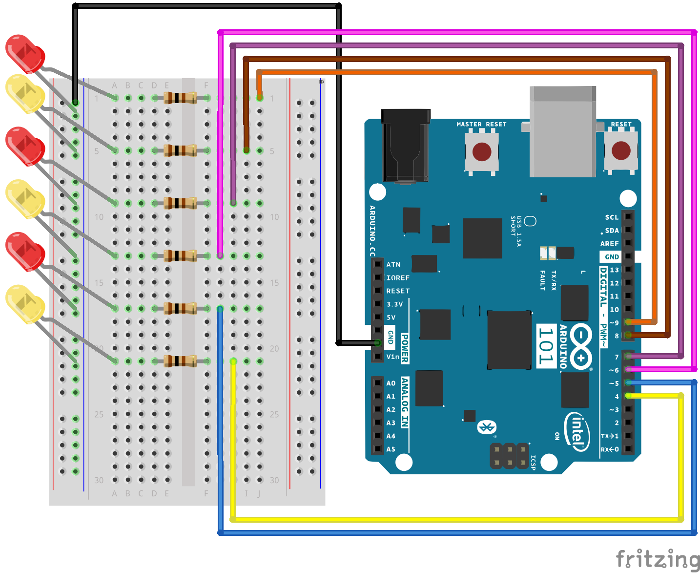
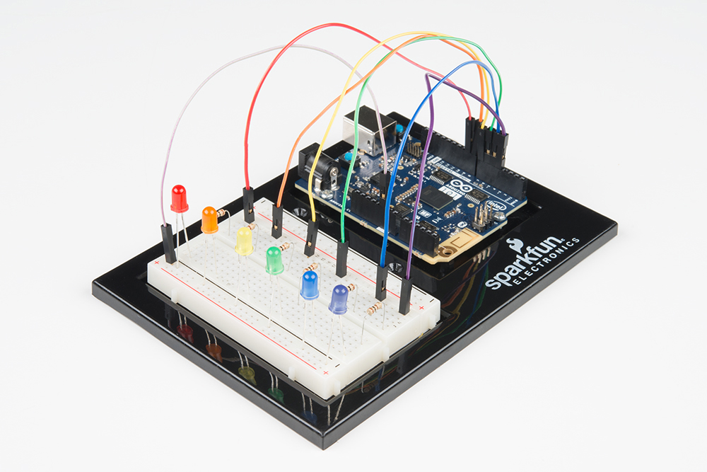
DEV-13984硬件接线
是否准备好开始对每个部件进行接线?请查看下面的接线图和接线表以了解如何连接每个部件。
| 极化组件 | 请特别注意组件用于指示如何在实验电路板上放置它的标记。极化组件只能按一个方向连接到电路。 |
实验的接线图
打开草图
在计算机上打开 Arduino IDE 软件。采用 Arduino 语言进行编码可控制电路。通过访问您先前下载并置于“示例”文件夹中的“101 SIK 指南代码”,来打开用于电路 4 的代码。
要打开该代码,请转到:文件 > 示例 > 101 SIK 指南代码 > Circuit_04
还可以将以下代码复制并粘贴到 Arduino IDE 中。点击“上传”,然后查看发生的情况!
language:cpp
/*
SparkFun Inventor's Kit
Example sketch 04

MULTIPLE LEDs

  Make six LEDs dance. Dance LEDs, dance!

This sketch was written by SparkFun Electronics,
with lots of help from the Arduino community.
This code is completely free for any use.
Visit http://learn.sparkfun.com/products/2 for SIK information.
Visit http://www.arduino.cc to learn more about Arduino.
*/

// To keep track of all the LED pins, we'll use an "array."
// An array lets you store a group of variables, and refer to them
// by their position, or "index." Here we're creating an array of
// six integers, and initializing them to a set of values:
int ledPins[] = {4,5,6,7,8,9};

void setup()
{
  //create a local variable to store the index of which pin we want to control
  int index;

  // For the for() loop below, these are the three statements:

  //   1\. index = 0;    Before starting, make index = 0.
  //   2\. index <= 5;   If index is less or equal to 5, run the following code
  //   3\. index++   Putting "++" after a variable means "add one to it".

  // When the test in statement 2 is finally false, the sketch
  // will continue.

  // This for() loop will make index = 0, then run the pinMode()
  // statement within the brackets. It will then do the same thing
  // for index = 2, index = 3, etc. all the way to index = 5.

  for(index = 0; index <= 5; index++)
  {
    pinMode(ledPins[index],OUTPUT);
  }
}

void loop()
{
  // This loop() calls functions that we've written further below.
  // We've disabled some of these by commenting them out (putting
  // "//" in front of them). To try different LED displays, remove
  // the "//" in front of the ones you'd like to run, and add "//"
  // in front of those you don't to comment out (and disable) those
  // lines.

  // Light up all the LEDs in turn
  oneAfterAnotherNoLoop();

  // Same as oneAfterAnotherNoLoop, but less typing
  //oneAfterAnotherLoop();

  // Turn on one LED at a time, scrolling down the line
  //oneOnAtATime();

  // Light the LEDs middle to the edges
  //pingPong();

  // Chase lights like you see on signs
  //marquee();

  // Blink LEDs randomly
  //randomLED();
}

/*
oneAfterAnotherNoLoop()
This function will light one LED, delay for delayTime, then light
the next LED, and repeat until all the LEDs are on. It will then
turn them off in the reverse order.
*/

void oneAfterAnotherNoLoop()
{
// time (milliseconds) to pause between LEDs
  int delayTime = 100;

  // turn all the LEDs on:

  digitalWrite(ledPins[0], HIGH);  //Turns on LED #0 (pin 4)
  delay(delayTime);                //wait delayTime milliseconds
  digitalWrite(ledPins[1], HIGH);  //Turns on LED #1 (pin 5)
  delay(delayTime);                //wait delayTime milliseconds
  digitalWrite(ledPins[2], HIGH);  //Turns on LED #2 (pin 6)
  delay(delayTime);                //wait delayTime milliseconds
  digitalWrite(ledPins[3], HIGH);  //Turns on LED #3 (pin 7)
  delay(delayTime);                //wait delayTime milliseconds
  digitalWrite(ledPins[4], HIGH);  //Turns on LED #4 (pin 8)
  delay(delayTime);                //wait delayTime milliseconds
  digitalWrite(ledPins[5], HIGH);  //Turns on LED #5 (pin 9)
  delay(delayTime);                //wait delayTime milliseconds

  // turn all the LEDs off:

  digitalWrite(ledPins[5], LOW);   //Turn off LED #5 (pin 9)
  delay(delayTime);                //wait delayTime milliseconds
  digitalWrite(ledPins[4], LOW);   //Turn off LED #4 (pin 8)
  delay(delayTime);                //wait delayTime milliseconds
  digitalWrite(ledPins[3], LOW);   //Turn off LED #3 (pin 7)
  delay(delayTime);                //wait delayTime milliseconds
  digitalWrite(ledPins[2], LOW);   //Turn off LED #2 (pin 6)
  delay(delayTime);                //wait delayTime milliseconds
  digitalWrite(ledPins[1], LOW);   //Turn off LED #1 (pin 5)
  delay(delayTime);                //wait delayTime milliseconds
  digitalWrite(ledPins[0], LOW);   //Turn off LED #0 (pin 4)
  delay(delayTime);                //wait delayTime milliseconds
}

/*
oneAfterAnotherLoop()

This function does exactly the same thing as oneAfterAnotherNoLoop(),
but it takes advantage of for() loops and the array to do it with
much less typing.
*/

void oneAfterAnotherLoop()
{
  int index;
  int delayTime = 100; // milliseconds to pause between LEDs
                       // make this smaller for faster switching

  // Turn all the LEDs on:

  // This for() loop will step index from 0 to 5
  // (putting "++" after a variable means add one to it)
  // and will then use digitalWrite() to turn that LED on.

  for(index = 0; index <= 5; index++)
  {
    digitalWrite(ledPins[index], HIGH);
    delay(delayTime);
  }

  // Turn all the LEDs off:

  // This for() loop will step index from 5 to 0
  // (putting "--" after a variable means subtract one from it)
  // and will then use digitalWrite() to turn that LED off.

  for(index = 5; index >= 0; index--)
  {
    digitalWrite(ledPins[index], LOW);
    delay(delayTime);
  }
}

/*
oneOnAtATime()

This function will step through the LEDs,
lighting only one at at time.
*/

void oneOnAtATime()
{
  int index;
  int delayTime = 100; // milliseconds to pause between LEDs
                       // make this smaller for faster switching

  // step through the LEDs, from 0 to 5

  for(index = 0; index <= 5; index++)
  {
    digitalWrite(ledPins[index], HIGH);  // turn LED on
    delay(delayTime);                    // pause to slow down
    digitalWrite(ledPins[index], LOW);   // turn LED off
  }
}

/*
pingPong()

This function will step through the LEDs,
lighting one at at time in both directions.
*/

void pingPong()
{
  int index;
  int delayTime = 100; // milliseconds to pause between LEDs
                       // make this smaller for faster switching

  // step through the LEDs, from 0 to 5

  for(index = 0; index <= 5; index++)
  {
    digitalWrite(ledPins[index], HIGH);  // turn LED on
    delay(delayTime);                    // pause to slow down
    digitalWrite(ledPins[index], LOW);   // turn LED off
  }

  // step through the LEDs, from 5 to 0

  for(index = 5; index >= 0; index--)
  {
    digitalWrite(ledPins[index], HIGH);  // turn LED on
    delay(delayTime);                    // pause to slow down
    digitalWrite(ledPins[index], LOW);   // turn LED off
  }
}

/*
marquee()

This function will mimic "chase lights" like those around signs.
*/

void marquee()
{
  int index;
  int delayTime = 200; // milliseconds to pause between LEDs
                       // Make this smaller for faster switching

  // Step through the first four LEDs
  // (We'll light up one in the lower 3 and one in the upper 3)

  for(index = 0; index <= 2; index++) // Step from 0 to 3
  {
    digitalWrite(ledPins[index], HIGH);    // Turn a LED on
    digitalWrite(ledPins[index+3], HIGH);  // Skip four, and turn that LED on
    delay(delayTime);                      // Pause to slow down the sequence
    digitalWrite(ledPins[index], LOW);     // Turn the LED off
    digitalWrite(ledPins[index+3], LOW);   // Skip four, and turn that LED off
  }
}

/*
randomLED()

This function will turn on random LEDs. Can you modify it so it
also lights them for random times?
*/

void randomLED()
{
  int index;
  int delayTime;

  // The random() function will return a semi-random number each
  // time it is called. See http://arduino.cc/en/Reference/Random
  // for tips on how to make random() even more random.

  index = random(5);    // pick a random number between 0 and 5
  delayTime = 100;

  digitalWrite(ledPins[index], HIGH);  // turn LED on
  delay(delayTime);                    // pause to slow down
  digitalWrite(ledPins[index], LOW);   // turn LED off
}
要注意的代码
int ledPins[] = {4,5,6,7,8,9};
必须管理许多变量时,“数组”是将它们分组在一起的便利方式。我们在此处要创建一个名为 ledPins 的整数数组,其中包含六个元素。每个元素都通过其索引进行引用。第一个元素的索引是 [0]。
digitalWrite(ledPins[0], HIGH);
可通过其位置引用数组中的元素。第一个元素处于位置 0,第二个元素处于位置 1,等等。您可引用使用了“ledPins[x]”的一个元素,其中 x 是位置。我们在这里将数字针脚 4 设为 HIGH,因为位置 0 处的数组元素是“4”。
index = random(5);
计算机会在每次运行时执行相同操作。但是有时您要随机执行操作,就像模拟投掷骰子。random() 函数是实现此目标的好方法。请参阅 http://arduino.cc/en/reference/random 以获取详细信息。
应看到的情况
这类似于实验 1,但您应看到所有 LED 闪烁,而非一个 LED。如果它们未闪烁,请确保正确装配了电路以及验证了代码并将它上传到开发板,或查看“故障诊断”部分。
故障诊断
某些 LED 未能亮起
很容易反向插入 LED。检查未运行的 LED 并确保它们处于正确的方向。
运行失序
由于有八根导线,因此容易使两根导线交叉。仔细检查第一个 LED 是否插入针脚 4,此后按顺序插入每个针脚。
重新开始
容易在没有注意的情况下意外地将导线放错位置。拔出每个部件并重新开始通常比尝试查出问题更容易。
实验 5:读取按下按钮操作
简介
到目前为止,我们将大部分精力集中在输出上。现在我们将转到另一方面,来尝试使用输入。在实验 2 中,我们使用了一个模拟输入来读取电位计。在本实验中,我们将使用数字输入读取最常见且简单的输入之一 – 按钮。我们将使用它在 RGB 上循环显示不同颜色。
所需部件
您需要以下部件:
- 1x 实验电路板
- 1x Arduino 101 或 Genuino 101 开发板
- 1x RGB LED
- 1x 100Ω 电阻
- 8x 跳线
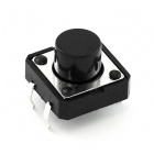
- 1x 按钮
- 1x 10K 电阻
没有 SIK?
如果您要执行本实验,但又没有 SIK,那么我们建议您使用这些部件:
您还需要一个 Arduino 101 或 Genuino 101 开发板。
Arduino 101
DEV-13787
Genuino 101
DEV-13984推荐阅读
继续进行本教程之前,我们建议您熟悉一下这些教程中的概念:
按钮简介
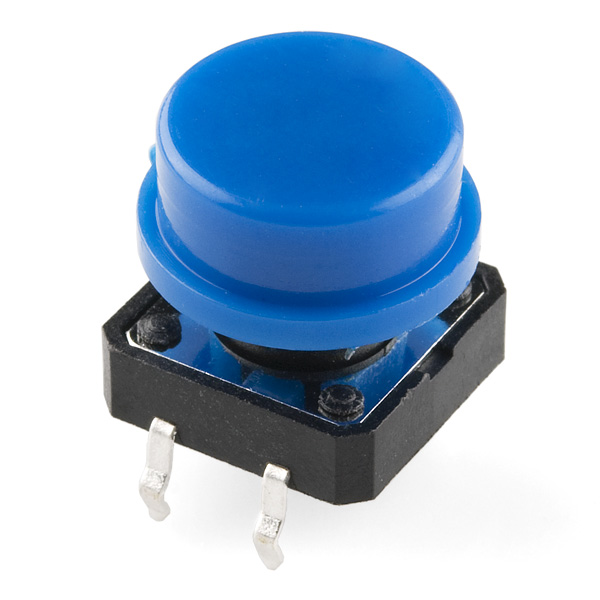
瞬息按钮仅当按下时才会关闭或完成电路。按钮具有四个针脚,它们分为两组,每组两个针脚。按下按钮并听到清脆的“咔哒”声时,按钮会桥接两组针脚,使电流流过电路。
如何知道哪些针脚已进行配对?此工具包中包含的按钮仅在一个方向上跨实验电路板沟槽进行安装。将按钮牢固地按入实验电路板(跨沟槽)之后,针脚按水平方向配对。朝向实验电路板顶部的针脚连接在一起,朝向实验电路板底部的针脚连接在一起。
注:并非所有按钮都采用此针脚格式。请参阅特定按钮的数据表以确定哪些针脚已进行配对。
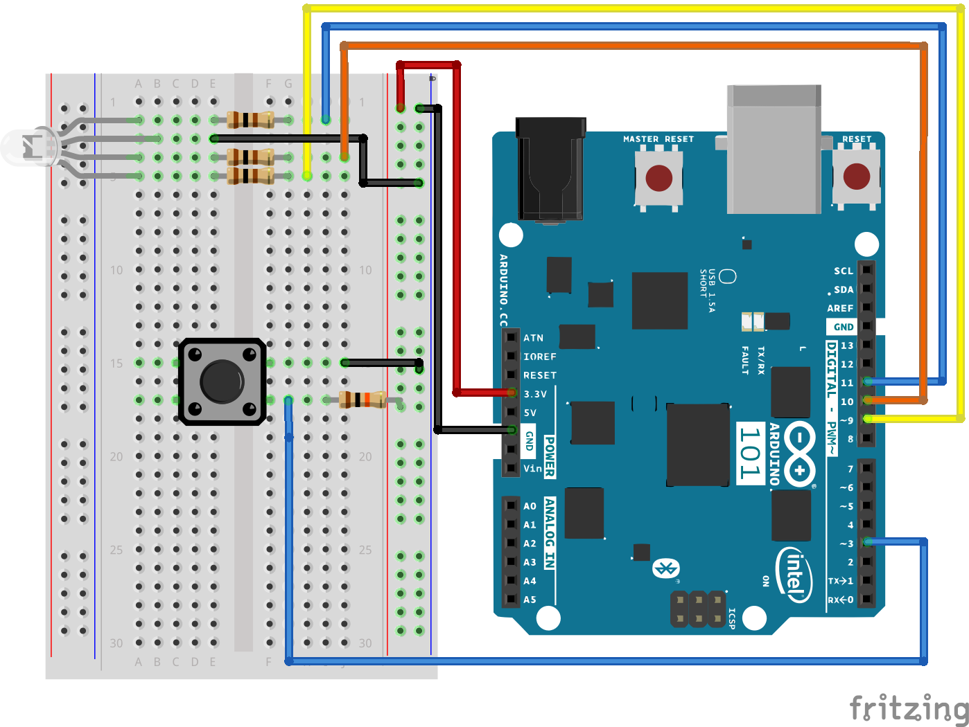
硬件接线
是否准备好开始对每个部件进行接线?请查看下面的接线图和接线表以了解如何连接每个部件。
| 极化组件 | 请特别注意组件用于指示如何在实验电路板上放置它的标记。极化组件只能按一个方向连接到电路。 |
实验的接线图
数字输入
我们以前曾将模拟针脚用于输入;现在我们还会将数字针脚用于输入。因为数字针脚只能识别 HIGH 和 LOW 信号,所以它们十分适用于与也只有“开”和“关”状态的按钮和开关相连接。
我们将按钮的一端接地,将另一端连接到数字针脚。当我们按下按钮时,针脚会接地,因此会由 Arduino 开发板读为“LOW”。
不过别着急 -- 未按下按钮时会发生什么情况?在此状态下,针脚会与任何对象断开连接,我们称之为“浮动”。那么针脚会读为什么?HIGH 还是 LOW?这难以判断,因为没有与 3.3V 或接地之间的实体连接。针脚可能读为任一状态。
为了解决此问题,我们将在信号针脚与 3.3V 之间连接一个小型(10K 或 10,000 欧姆)电阻。此“上拉”电阻会确保当您未按下按钮时,针脚仍具有与 3.3 伏之间的弱连接,因此读为 HIGH。
高级:当您习惯于使用上拉电阻并且知道何时需要使用它们时,您可以在 Arduino 中的 ATmega 处理器上激活内部上拉电阻。请参阅 http://arduino.cc/en/Tutorial/DigitalPins 以获取信息。
打开草图
在计算机上打开 Arduino IDE 软件。采用 Arduino 语言进行编码可控制电路。通过访问您先前下载并置于“示例”文件夹中的“101 SIK 指南代码”,来打开用于电路 5 的代码。
要打开该代码,请转到:文件 > 示例 > 101 SIK 指南代码 > Circuit_05
还可以将以下代码复制并粘贴到 Arduino IDE 中。点击“上传”,然后查看发生的情况!
language:cpp
/*
SparkFun Inventor's Kit
Example sketch 05

PUSH BUTTONS

  Use pushbuttons for digital input

This sketch was written by SparkFun Electronics,
with lots of help from the Arduino community.
This code is completely free for any use.
Visit http://learn.sparkfun.com/products/2 for SIK information.
Visit http://www.arduino.cc to learn about the Arduino.

*/

// First we'll set up constants for the pin numbers.
// This will make it easier to follow the code below.

 // pushbutton pin
 const int buttonPin = 3;

 //RGB LED pins
 const int redPin = 11;
 const int greenPin = 10;
 const int bluePin = 9;

//create a variable to store a counter and set it to 0
int counter = 0;
void setup()
{
  // Set up the pushbutton pins to be an input:
  pinMode(buttonPin, INPUT);

  // Set up the RGB pins to be an outputs:
  pinMode(redPin, OUTPUT);
  pinMode(greenPin,OUTPUT);
  pinMode(bluePin,OUTPUT);
}

void loop()
{
 // local variable to hold the pushbutton states
  int buttonState;

  //read the digital state of buttonPin with digitalRead() function and store the           //value in buttonState variable
  buttonState = digitalRead(buttonPin);

  //if the button is pressed increment counter and wait a tiny bit to give us some          //time to release the button
  if (buttonState == LOW) // light the LED
  {
    counter++;
    delay(150);
  }

  //use the if satement to check the value of counter. If counter is equal to 0 all         //pins are off
  if(counter == 0)
  {
   digitalWrite(redPin,LOW);
   digitalWrite(greenPin,LOW);
   digitalWrite(bluePin,LOW);
  }

  //else if counter is equal to 1, redPin is HIGH
  else if(counter == 1)
  {
   digitalWrite(redPin,HIGH);
   digitalWrite(greenPin,LOW);
   digitalWrite(bluePin,LOW);
  }

  //else if counter is equal to 2 greenPin is HIGH
  else if(counter ==2)
  {
   digitalWrite(redPin,LOW);
   digitalWrite(greenPin,HIGH);
   digitalWrite(bluePin,LOW);
  }

  //else if counter is equal to 3 bluePin is HIGH
  else if(counter ==3)
  {
   digitalWrite(redPin,LOW);
   digitalWrite(greenPin,LOW);
   digitalWrite(bluePin,HIGH);
  }

  //else reset the counter to 0 (which turns all pins off)
  else
  {
   counter =0;
  }
}
要注意的代码
pinMode(buttonPin, INPUT);
数字针脚可以用作输入以及输出。执行任一操作之前,需要向 Arduino 告知您的目标方向。
buttonState = digitalRead(buttonPin);
要读取数字输入,可使用 digitalRead() 函数。它会在针脚上存在 3.3V 时返回 HIGH,在针脚上存在 0V 时返回 LOW。
if (button1State == LOW)
因为我们已将按钮连接到 GND,所以它会在按下时读为 LOW。我们在这里使用“等值”运算符(“==”)来了解是否按下了按钮。
应看到的情况
您应在按下任一按钮时看到 LED 亮起,在同时按下两个按钮时看到 LED 熄灭。(请查看代码以查明原因!)如果它未运行,请确保正确装配了电路以及验证了代码并将它上传到开发板,或查看“故障诊断”部分。

故障诊断
指示灯未亮起
按钮是方形的,因此容易将其放错。将它旋转 90 度,然后看看它是否开始运行。
感到乏味
别担心;这些电路全都极其精简,以便您能轻松尝试使用各个组件,但是一旦您将它们组合在一起,便可获得无穷乐趣。
实验 6:读取 SPDT 开关
简介
在前面的实验中,您使用了按钮作为数字输入。在本实验中,您将探索另一个数字输入,即 SPDT(单刀 - 双掷)开关。您将使用该开关选择两个 LED 中的哪个会闪烁。
所需部件
您需要以下部件:
- 1x 实验电路板
- 1x Arduino 101 或 Genuino 101 开发板
- 2x LED(1 个红色,1 个黄色)
- 2x 100Ω 电阻
- 8x 跳线
- 1x SPDT 开关
没有 SIK?
如果您要执行本实验,但又没有 SIK,那么我们建议您使用这些部件:
您还需要一个 Arduino 101 或 Genuino 101 开发板。
Arduino 101
DEV-13787
Genuino 101
DEV-13984推荐阅读
继续进行本教程之前,我们建议您熟悉一下这些教程中的概念:
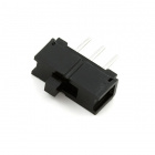
单刀 - 双掷 (SPDT) 开关简介

单刀 - 双掷 (SPDT) 开关在中央有一个公共针脚,此外是其他两个针脚,它们根据开关的位置,会连接到或未连接到公共(中央)针脚。要采用与按钮相似的方式读取开关,需要将公共针脚连接到 101 开发板上的数字通用输入/输出 (GPIO) 针脚,并将其他针脚连接到 3.3V 和接地。哪个针脚连接到哪个位置并不重要。移动开关时,公共针脚会是 HIGH(连接到 3.3V)或 LOW(接地)。
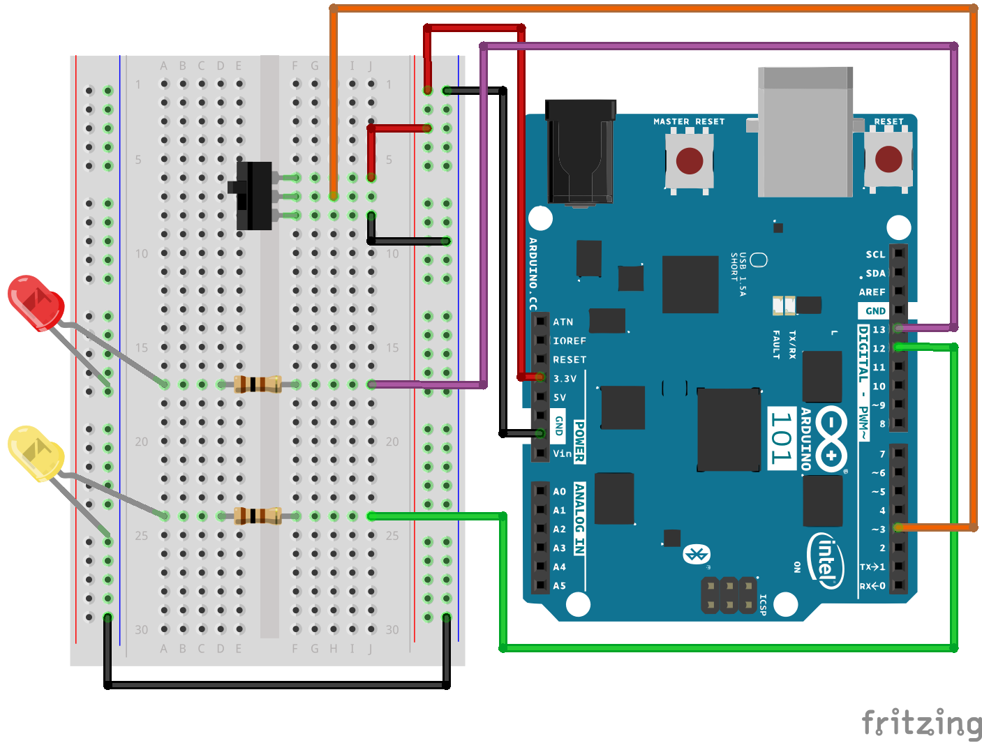
硬件接线
是否准备好开始对每个部件进行接线?请查看下面的接线图和接线表以了解如何连接每个部件。
| 极化组件 | 请特别注意组件用于指示如何在实验电路板上放置它的标记。极化组件只能按一个方向连接到电路。 |
实验的接线图
打开草图
在计算机上打开 Arduino IDE 软件。采用 Arduino 语言进行编码可控制电路。通过访问您先前下载并置于“示例”文件夹中的“101 SIK 指南代码”,来打开用于电路 6 的代码。
要打开该代码,请转到:文件 > 示例 > 101 SIK 指南代码 > Circuit_06
还可以将以下代码复制并粘贴到 Arduino IDE 中。点击“上传”,然后查看发生的情况!
language:cpp
/*
SparkFun Inventor's Kit
Example sketch 06

SPDT Switch

Use a Single Pole - Double Throw Switch (SPDT) to select an LED to blink

This sketch was written by SparkFun Electronics,
with lots of help from the Arduino community.
This code is completely free for any use.
Visit http://learn.sparkfun.com/products/2 for SIK information.
Visit http://www.arduino.cc to learn more about Arduino.
*/

// Create constants for the pins we will be using
const int switchPin = 3;
const int led1Pin = 12;
const int led2Pin =  13;

void setup()
{
  // Set up the switch pins to be an input:
  pinMode(switchPin, INPUT);

  // Set up the LED pins to be an output:
  pinMode(led1Pin,OUTPUT);
  pinMode(led2Pin,OUTPUT);
}

void loop()
{
  // variables to hold the switch state
  int switchVal;

  // Since a switch has only two states, either HIGH (3.3V)
  // or LOW (GND) there is no way for you to have a floating point situation so there       //is no need for a pulldown resistor.

  //store the switch value to the switchVal variable
  switchVal = digitalRead(switchPin);

 //if switchVal is HIGH blink led1Pin
 if(switchVal == HIGH)
 {
   digitalWrite(led1Pin,HIGH);
   delay(500);
   digitalWrite(led1Pin,LOW);
   delay(500);
 }
 //else blink led2Pin
 else
 {
   digitalWrite(led2Pin,HIGH);
   delay(500);
   digitalWrite(led2Pin,LOW);
   delay(500);
 }
}
要注意的代码
pinMode(switchPin, INPUT);
数字针脚可以用作输入以及输出。执行任一操作之前,需要向 Arduino 101 告知您的目标方向。
switchVal = digitalRead(switchPin);
要读取数字输入,可使用 digitalRead() 函数。它会在针脚上存在 3.3V 时返回 HIGH,在针脚上存在 0V 时返回 LOW。
if (switchVal == LOW)
因为我们已将按钮连接到 GND,所以它会在按下时读为 LOW。我们在这里使用“等值”运算符(“==”)来了解是否按下了按钮。
应看到的情况
根据开关的状态,不同的 LED 将闪烁。如果移动开关以将信号针脚连接到 3.3V (HIGH),则 LED 1 将闪烁。如果反转开关并使信号针脚接地,则 LED 2 将开始闪烁,LED 1 将熄灭。
故障诊断
指示灯未亮起
开关的导线彼此紧挨着。确保信号位于中央,而电压和接地位于外侧针脚上。如果将接地与电压连接在一起,则开发板会短路并关闭。
确保电源 LED 已亮起。如果它熄灭,请从针脚 3 拔出信号导线,查看是否更改了任何内容。如果 101 开发板短路,则它会关闭自己以保护电路。您还可能必须重新启动计算机以便可以重新访问串行端口。
感到乏味
别担心;这些电路全都极其精简,以便您能轻松尝试使用各个组件,但是一旦您将它们组合在一起,便可获得无穷乐趣。
实验 7:读取光敏电阻
简介
在实验 2 中,您使用了电位计,它会基于旋钮的转动来更改电阻,进而更改模拟输入针脚所读取的电压。在此电路中,您将使用光敏电阻,它会基于传感器收到的光量来更改电阻。您将读取房间的光量值,在房间黑暗时使 LED 亮起,在房间明亮时使它熄灭。就是这样;您将构建一个夜间照明灯!
所需部件
您需要以下部件:
- 1x 实验电路板
- 1x Arduino 101 或 Genuino 101 开发板
- 1x LED
- 1x 100Ω 电阻
- 7x 跳线
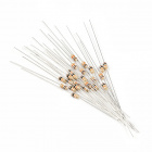
- 1x 光敏电阻
- 1x 10K 电阻
没有 SIK?
如果您要执行本实验,但又没有 SIK,那么我们建议您使用这些部件:

您还需要一个 Arduino 101 或 Genuino 101 开发板。
Arduino 101
DEV-13787
Genuino 101
DEV-13984光敏电阻简介
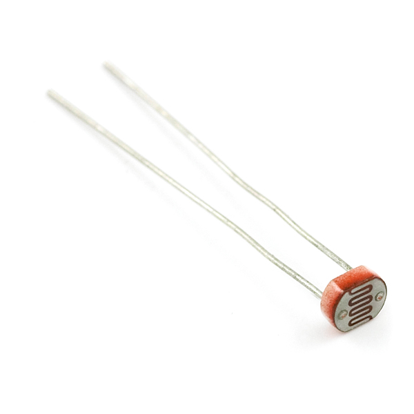
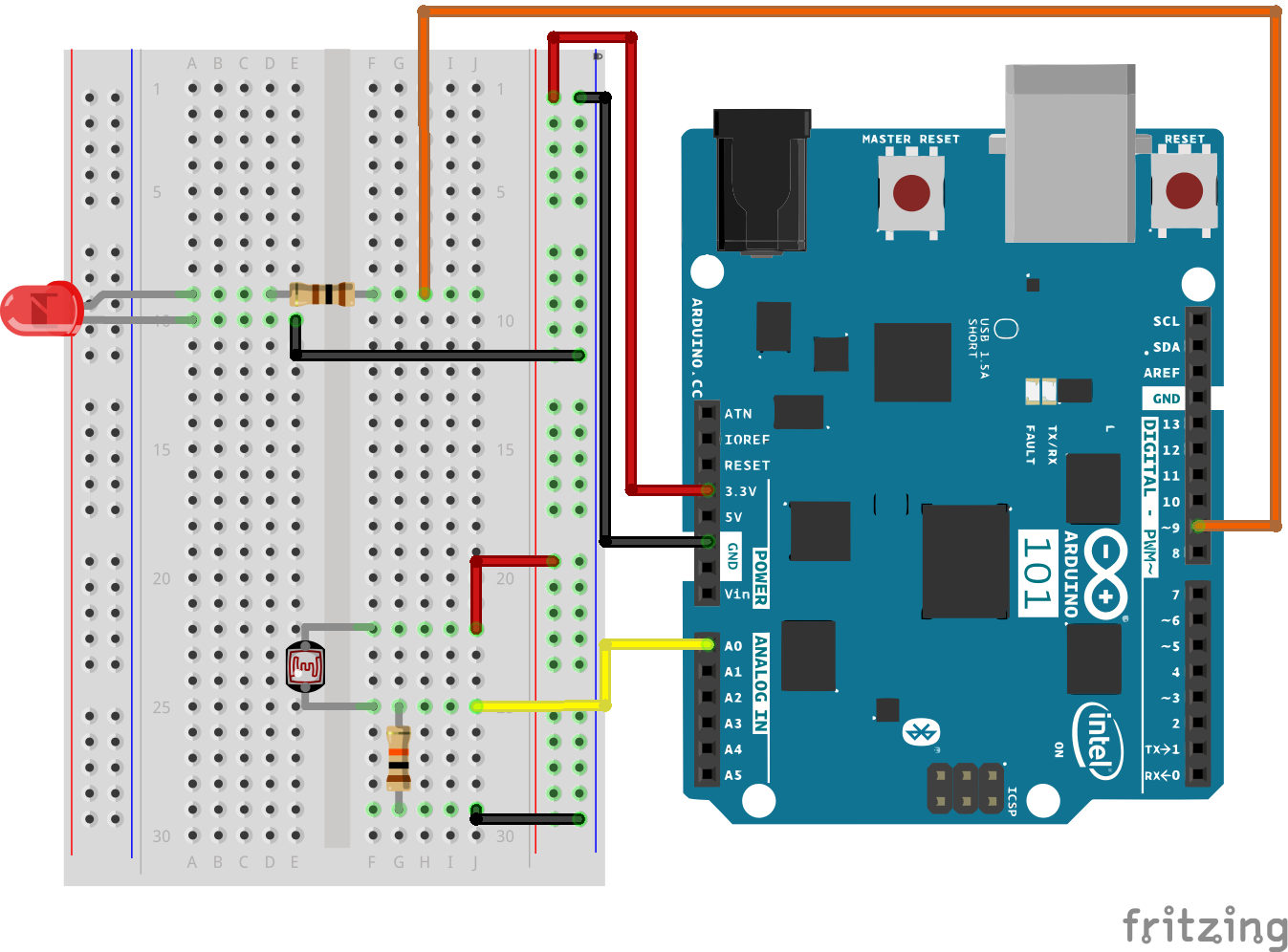
光敏电阻会基于对它照射的光量来更改其电阻。要将此光敏电阻与 101 开发板结合使用,您需要使用一个 10K 欧姆电阻构建一个分压器,如本实验的接线图所示。101 开发板无法读取电阻的变化,只能读取电压的变化。通过分压器可以将电阻的变化转换为对应的电压值。
通过分压器可以在基于电压的系统中使用基于电阻的传感器(如光敏电阻)。随着您探索其他传感器,您将发现更多类似于光敏电阻只有两个针脚的基于电阻的传感器。要将它们与 101 开发板结合使用,您需要构建一个分压器(类似于本实验中的分压器)。如需了解有关电阻的更多常规信息,请查看我们有关电阻的教程以及我们有关分压器的教程。
注:确保在分压器中使用 10K 欧姆电阻以及此工具包中的传感器。否则您会获得奇怪且不一致的结果。
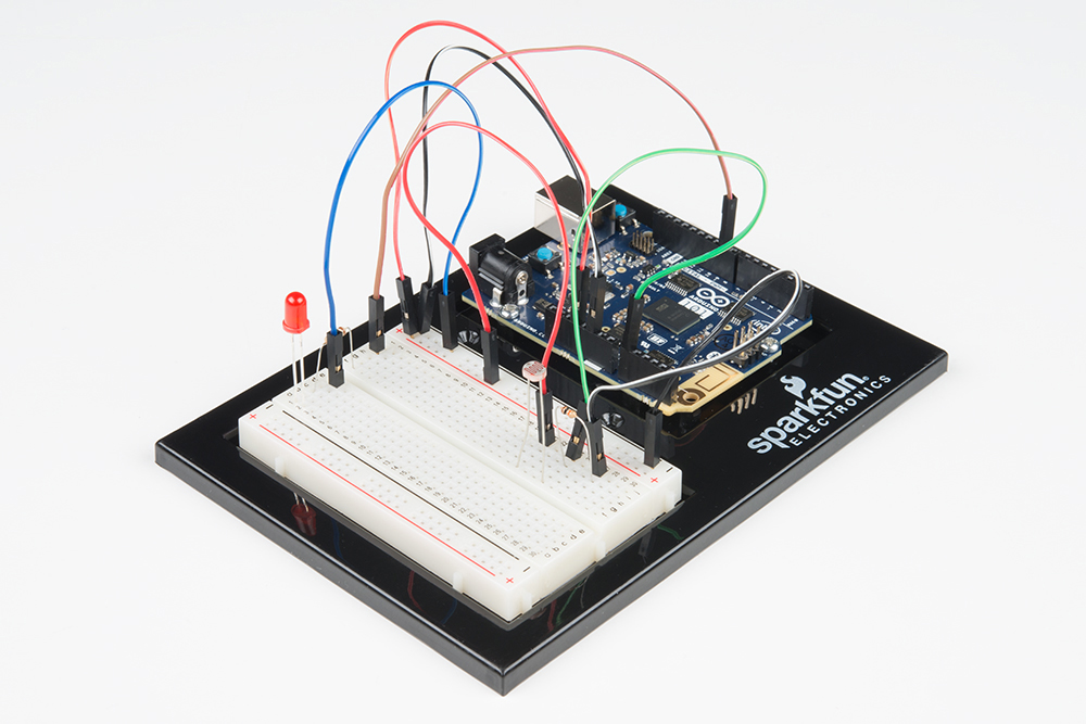
硬件接线
是否准备好开始对每个部件进行接线?请查看下面的接线图以了解如何连接每个部件。
| 极化组件 | 请特别注意组件用于指示如何在实验电路板上放置它的标记。极化组件只能按一个方向连接到电路。 |
实验的接线图
打开草图
在计算机上打开 Arduino IDE 软件。采用 Arduino 语言进行编码可控制电路。通过访问您先前下载并置于“示例”文件夹中的“101 SIK 指南代码”,来打开用于电路 7 的代码。
要打开该代码,请转到:文件 > 示例 > 101 SIK 指南代码 > Circuit_07
还可以将以下代码复制并粘贴到 Arduino IDE 中。点击“上传”,然后查看发生的情况!
language:cpp
/*
SparkFun Inventor's Kit
Example sketch 07

PHOTORESISTOR

  Read a photoresistor (light sensor) to detect "darkness" and turn on an LED when it is "dark" and turn back off again when it is "bright."

This sketch was written by SparkFun Electronics,
with lots of help from the Arduino community.
This code is completely free for any use.
Visit http://learn.sparkfun.com/products/2 for SIK information.
Visit http://www.arduino.cc to learn more about Arduino.
*/

// As usual, we'll create constants to name the pins we're using.
// This will make it easier to follow the code below.

const int sensorPin = 0;
const int ledPin = 9;

// We'll also set up some global variables for the light level a calibration value and     //and a raw light value
int lightCal;
int lightVal;

void setup()
{
  // We'll set up the LED pin to be an output.
  pinMode(ledPin, OUTPUT);
  lightCal = analogRead(sensorPin);
  //we will take a single reading from the light sensor and store it in the lightCal        //variable. This will give us a prelinary value to compare against in the loop
}

void loop()
{
  //Take a reading using analogRead() on sensor pin and store it in lightVal
  lightVal = analogRead(sensorPin);

  //if lightVal is less than our initial reading (lightCal) minus 50 it is dark and         //turn pin 9 HIGH. The (-50) part of the statement sets the sensitivity. The smaller       //the number the more sensitive the circuit will be to variances in light.
  if(lightVal < lightCal - 50)
  {
    digitalWrite(9,HIGH);
  }

  //else, it is bright, turn pin 9 LOW
  else
  {
    digitalWrite(9,LOW);
  }

}
要注意的代码
lightCal = analogRead(sensorPin); lightCal 是校准变量。101 开发板在设置中采用光传感器的单个读数,并在循环中使用此值与 lightVal 进行比较。此值在循环中不会更改,因为它是在设置函数中设置的。要更新此值,可以按“重置”按钮或关闭再打开开发板。
if(lightVal < lightCal -50) 如果在循环中不断更新的光量值变量小于在设置中设置的校准值减去 50,则表示黑暗,LED 应亮起。此语句的 (-50) 部分是灵敏度值。该值越高,电路的灵敏度便越低;该值越低,便对光照条件更灵敏。
应看到的情况
您应看到 LED 在房间黑暗时亮起,在变亮时熄灭。尝试将手盖住传感器,然后移开。如果它未运行,请确保正确装配了电路以及验证了代码并将它上传到开发板,或查看“故障诊断”部分。
故障诊断
LED 不亮
您可能在上传代码时使影子覆盖了传感器。确保传感器暴露在房间的环境光线中,然后按“主重置”按钮或重新上传代码。这会重置设置中的校准值。
仍未完全运行
您的逻辑语句可能错误。仔细检查代码,并尝试将灵敏度级别调低或调高一点。确保 if() 语句后面没有分号。这是常见错误,并且难以发现!
实验 8:使用 RGB 混合颜色
简介
在此电路中,您将使用多个电位计。您在实验 1 中使用了单个电位计。现在我们将更进一步,使用三个电位计!为何使用三个?您将使用每个电位计分别控制一个 RGB LED 的三种颜色(红色、绿色和蓝色)的亮度,以便形成一些比您在实验 3 中所使用的基本颜色更丰富的颜色。
拿出您的画笔,准备好绘制彩虹!
您需要以下部件:
- 1x 实验电路板
- 1x Arduino 101 或 Genuino 101 开发板
- 1x 共阴极 RGB LED
- 3x 100Ω 电阻
- 15x 跳线
- 3x 电位计
没有 SIK?
如果您要执行本实验,但又没有 SIK,那么我们建议您使用这些部件:
您还需要一个 Arduino 101 或 Genuino 101 开发板。
Arduino 101
DEV-13787
Genuino 101
DEV-13984推荐阅读
继续进行本实验之前,我们建议您熟悉以下教程中的概念:
硬件接线
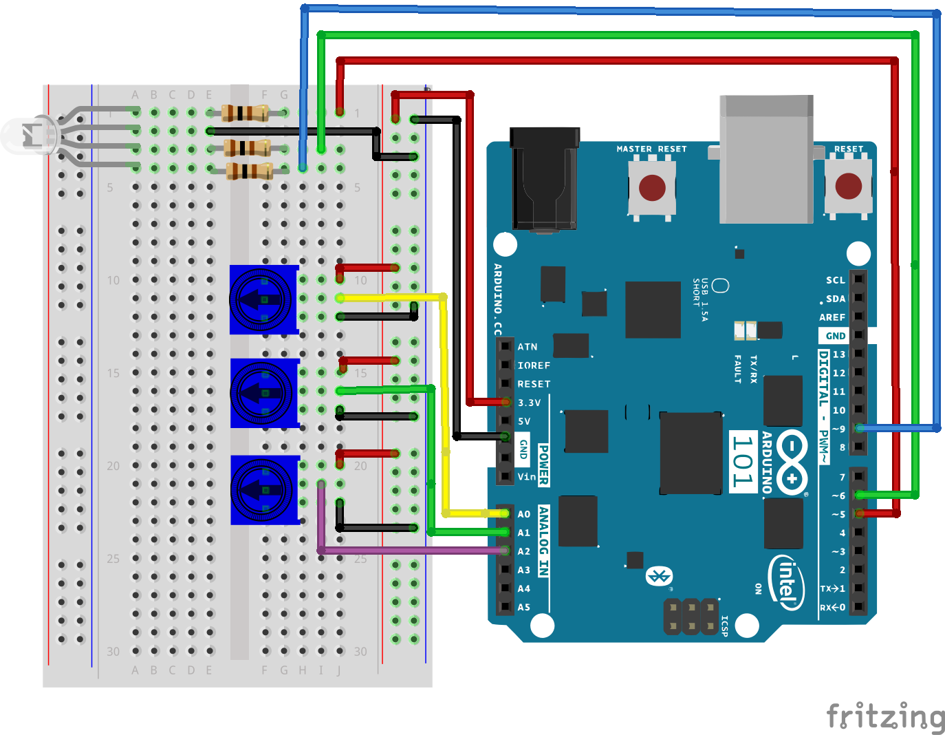
是否准备好开始对每个部件进行接线?请查看下面的接线图和接线表以了解如何连接每个部件。
| 极化组件 | 请特别注意组件用于指示如何在实验电路板上放置它的标记。极化组件只能按一个方向连接到电路。在表中,极化组件使用黄色警告三角突出显示。 |
实验的接线图
打开草图
在计算机上打开 Arduino IDE 软件。采用 Arduino 语言进行编码可控制电路。通过访问您先前下载并置于“示例”文件夹中的“SIK 指南代码”,来打开用于电路 8 的代码。
要打开该代码,请转到:文件 > 示例 > SIK 指南代码 > Circuit_08
将以下代码复制并粘贴到 Arduino IDE 中。点击“上传”,然后查看发生的情况!
language:cpp
/* SparkFun Inventor's Kit
Example sketch 08

POTENTIOMETER

  Measure the position of each potentiometer and map it to
  the red, green and blue values! Then write those values to the RGB LED.

This sketch was written by SparkFun Electronics,
with lots of help from the Arduino community.
This code is completely free for any use.
Visit http://learn.sparkfun.com/products/2 for SIK information.
Visit http://www.arduino.cc to learn more about Arduino.
*/

//create constants for the three analog input pins
const int redPot = 0;
const int greenPot = 1;
const int bluePot = 2;

//create constants for the three RGB pulse width pins
const int redPin = 5;
const int greenPin = 6;
const int bluePin = 9;

//create variables to store the red, green and blue values
int redVal;
int greenVal;
int blueVal;

void setup()
{
  //set the RGB pins as outputs
  pinMode(redPin, OUTPUT);
  pinMode(greenPin, OUTPUT);
  pinMode(bluePin, OUTPUT);
}

void loop()
{
  //read the three analog input pins and store their value to the color variables
  redVal = analogRead(redPot);
  greenVal = analogRead(greenPot);
  blueVal = analogRead(bluePot);

  //use the map() function to scale the 10 bit (0-1023) analog input value to an 8 bit
  //(0-255) PWM, or analogWrite() signal. Then store the new mapped value back in the
  //color variable

  redVal = map(redVal, 0, 1023, 0, 255);
  greenVal = map(greenVal, 0, 1023, 0, 255);
  blueVal = map(blueVal, 0, 1023, 0, 255);

  // use the analogWrite() function to write the color values to their respective
  // RGB pins.
  analogWrite(redPin, redVal);
  analogWrite(greenPin, greenVal);
  analogWrite(bluePin, blueVal);
}
要注意的代码
analogWrite(6,233); analogWrite 函数用于对 101 开发板的针脚 9、6、5 和 3 上的 PWM 进行控制。可以写入处于 0 - 255 范围内的值,其中 255 表示完全亮起,0 表示完全熄灭。
lightLevel = map(lightLevel, 0, 1023, 0, 255);
参数
map(value, fromLow, fromHigh, toLow, toHigh)
value:要映射的数字
fromLow:值当前范围的下限
fromHigh:值当前范围的上限
toLow:值目标范围的下限
toHigh:值目标范围的上限
当我们使用 analogRead() 读取模拟信号时,它会是介于 0 到 1023 之间的数字。但是当我们要使用 analogWrite() 驱动 PWM 针脚时,它需要介于 0 到 255 之间的数字。我们可以使用 map() 函数将较大范围“压缩”为较小范围。请参阅 Arduino 的映射参考页面以了解详细信息。
应看到的情况
您在调整三个电位计时应看到 RGB LED 更改颜色。每个电位计分别控制一种特定颜色(红色、绿色和蓝色)。当所有电位计都调整为最大值时,您应看到 RGB 发出白光。当它们全都调整为最小值时,RGB 应完全熄灭。如果不是这样,请查看下面的“故障诊断”部分。
故障诊断
偶发运行
这最可能是由于与电位计针脚之间的连接稍微有些接触不良。解决此问题的方法通常可以是按下电位计,或将电位计电路移动到实验电路板上的其他某个位置。
未运行
确保没有意外地将滑动片(中央针脚,即电位计中的电阻元件)连接到数字针脚 0 而不是模拟针脚 0。+(电源针脚下方的针脚行)。
LED 未亮起?
LED 只能按一个方向运行。仔细检查连接。
实验 9:读取温度传感器
简介
温度传感器正如其字面意思一样 – 用于测量环境温度的传感器。在本实验中,您将从温度传感器读取原始的 0-1023 值,计算实际温度,然后通过串行监视器打印出来。不知道什么是串行监视器?请完成本实验以进行了解!
所需部件
您需要以下部件:
- 1x 实验电路板
- 1x Arduino 101 或 Genuino 101 开发板
- 3x 跳线
- 1x TMP36 温度传感器
没有 SIK?
如果您要执行本实验,但又没有 SIK,那么我们建议您使用这些部件:
Temperature Sensor - TMP36
SEN-10988您还需要一个 Arduino 101 或 Genuino 101 开发板。
Arduino 101
DEV-13787
Genuino 101
DEV-13984TMP36 温度传感器简介
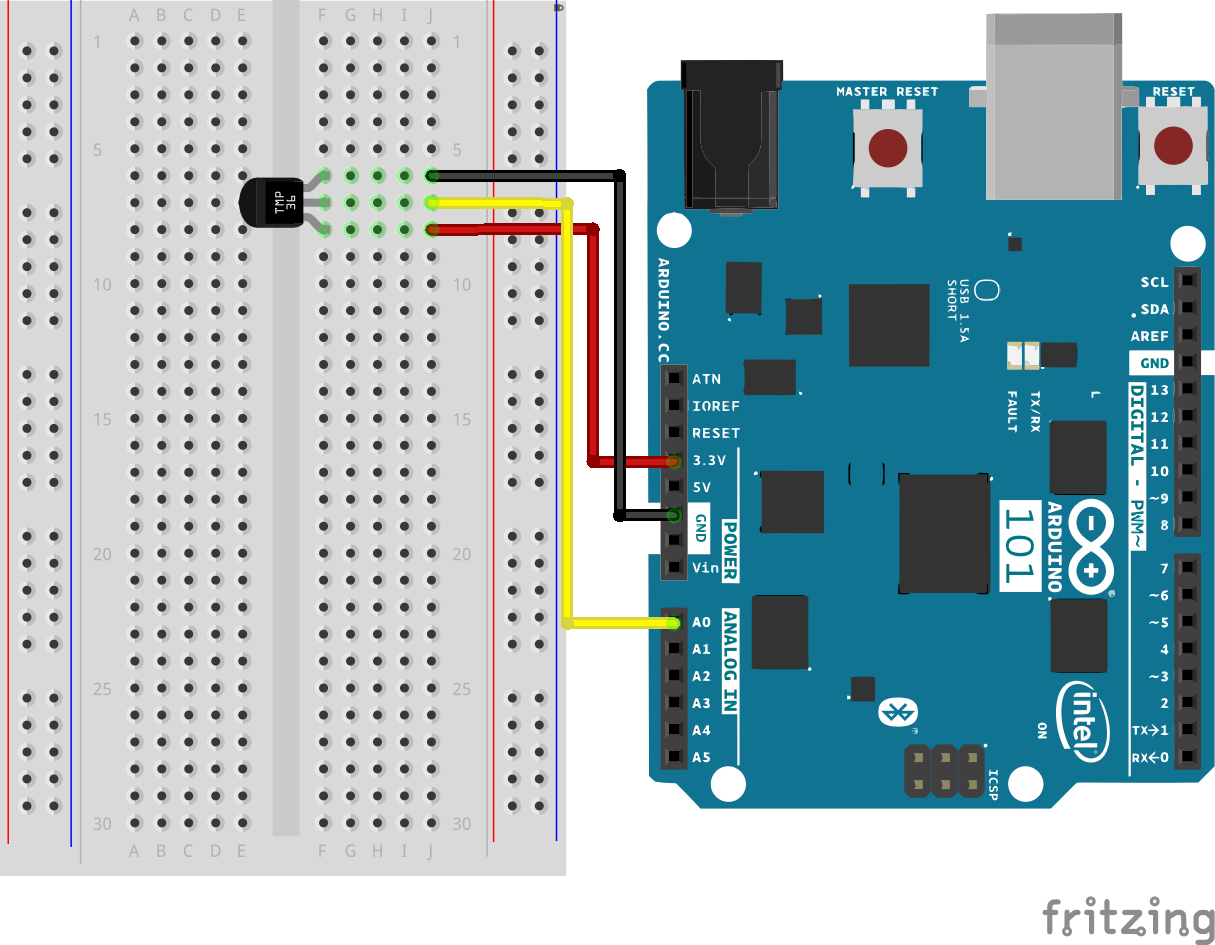
TMP36 是低压摄氏度精度温度传感器。它可提供与摄氏温度成线性比例的电压输出。而且无需任何外部校准即可提供以下典型精确性:+25°C 时为 ±1°C,处于 −40°C 到 +125°C 温度范围时为 ±2°C。输出电压可以方便地使用比例系数 10 mV/°C 转换为温度。
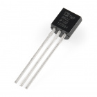
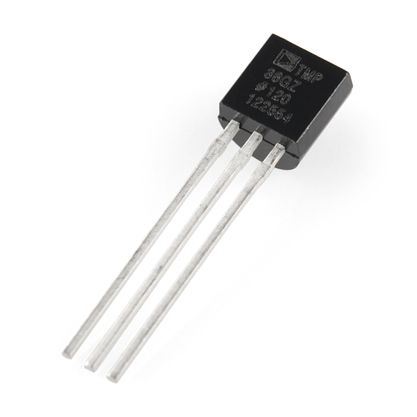
如果您查看上面带有文本的平面,则中央针脚是信号针脚;左侧针脚是电源电压(在本教程是 3.3V),而右侧针脚接地。
专业提示:TMP36 的外观十分类似于晶体管。可将一点指甲油滴在 TMP36 顶部,以便易于发现。
硬件接线
是否准备好开始对每个部件进行接线?请查看下面的接线图以了解如何连接每个部件。
| 极化组件 | 请特别注意组件用于指示如何在实验电路板上放置它的标记。极化组件只能按一个方向连接到电路。 |
请注意:温度传感器只能按一个方向连接到电路。请参阅下文以了解温度传感器 - TMP36 的针脚输出。
实验的接线图
打开草图
在计算机上打开 Arduino IDE 软件。采用 Arduino 语言进行编码可控制电路。通过访问您先前下载并置于“示例”文件夹中的“101 SIK 指南代码”,来打开用于电路 9 的代码。
要打开该代码,请转到:文件 > 示例 > 101 SIK 指南代码 > Circuit_09
还可以将以下代码复制并粘贴到 Arduino IDE 中。点击“上传”,然后查看发生的情况!
language:cpp
/*
SparkFun Inventor's Kit
Example sketch 07

TEMPERATURE SENSOR

  Use the "serial monitor" window to read a temperature sensor.

This sketch was written by SparkFun Electronics,
with lots of help from the Arduino community.
This code is completely free for any use.
Visit http://learn.sparkfun.com/products/2 for SIK information.
Visit http://www.arduino.cc to learn more about Arduino.

*/

//analog input pin constant
const int tempPin = 0;

//raw reading variable
int tempVal;

//voltage variable
float volts;

//final temperature variables
float tempC;
float tempF;

void setup()
{
  // start the serial port at 9600 baud
  Serial.begin(9600);
}

void loop()
{
 //read the temp sensor and store it in tempVal
 tempVal = analogRead(tempPin);

 //print out the 10 value from analogRead
 Serial.print("TempVal = ");
 Serial.print(tempVal);

 //print a spacer
 Serial.print(" **** ");

 //converting that reading to voltage by multiplying the reading by 3.3V (voltage of       //the 101 board)
 volts = tempVal * 3.3;
 volts /= 1023.0;

 //print out the raw voltage over the serial port
 Serial.print("volts: ");
 Serial.print(volts, 3);

 //print out divider
 Serial.print(" **** ");

 //calculate temperature celsius from voltage
 //equation found on the sensor spec.
 tempC = (volts - 0.5) * 100 ;

// print the celcius temperature over the serial port
Serial.print(" degrees C: ");
Serial.print(tempC);

//print spacer
 Serial.print(" **** ");

// Convert from celcius to fahrenheit
tempF = (tempC * 9.0 / 5.0) + 32.0;

//print the fahrenheit temperature over the serial port
Serial.print(" degrees F: ");
Serial.println(tempF);

//wait a bit before taking another reading
delay(1000);
}
要注意的代码
Serial.begin(9600);
使用串行监视器之前,您必须调用 Serial.begin() 以对它进行初始化。9600 是“波特率”或通信速度。两个设备相互通信时,两者必须设置为相同速度。
Serial.print(tempC);
Serial.print() 命令非常智能。它可以打印出您可向它传递的几乎任何内容,包括所有类型的变量、带引号的文本(又称为“字符串”)等。请参阅 http://arduino.cc/en/serial/print 以了解详细信息。
Serial.println(tempF);
Serial.print() 会在相同行上打印所有内容。
Serial.println() 会移动到下一行。通过将这两个命令结合使用,您可以创建易于阅读的文本和数据打印输出。
应看到的情况
您应能够在 Arduino IDE 中的串行监视器上读取温度传感器所检测到的温度。如果它未运行,请确保正确装配了电路以及验证了代码并将它上传到开发板,或查看“故障诊断”部分。
您在 Arduino IDE 的串行监视器上应看到的示例:
TempVal = 223 **** 伏:0.719 **** 摄氏度:21.94 **** 华氏度:71.48
TempVal = 224 **** 伏:0.723 **** 摄氏度:22.26 **** 华氏度:72.06
TempVal = 224 **** 伏:0.723 **** 摄氏度:22.26 **** 华氏度:72.06
TempVal = 224 **** 伏:0.723 **** 摄氏度:22.26 **** 华氏度:72.06
TempVal = 224 **** 伏:0.723 **** 摄氏度:22.26 **** 华氏度:72.06
TempVal = 224 **** 伏:0.723 **** 摄氏度:22.26 **** 华氏度:72.06
TempVal = 223 **** 伏:0.719 **** 摄氏度:21.94 **** 华氏度:71.48
TempVal = 223 **** 伏:0.719 **** 摄氏度:21.94 **** 华氏度:71.48
故障诊断
似乎没有任何情况发生
此程序无法向外指示它是否在运行。要查看结果,必须打开 Arduino IDE 的串行监视器(按照上一页的说明执行)。
显示的数据无意义
发生这种情况的原因是,串行监视器在采用与预期不同的速度接收数据。要修复此问题,请单击显示“*** 波特率”的下拉框,将它更改为“9600 波特率”。
温度值未变化
尝试用手指捏住传感器以加热它,或将一个冰袋压在传感器上以冷却它。
温度传感器非常热!
您将它接反了!立即拔下 Arduino,让传感器冷却,然后仔细检查接线。如果您处理速度足够快,则传感器可能尚未损坏,仍可运行。
实验 10:驱动伺服马达
简介
本实验将向您简介伺服马达,伺服马达是一种智能马达,您可以指示它旋转到特定角度位置。您将对它进行编程,以旋转到一系列位置,然后在其整个运动范围内进行扫描,随后重复操作。
所需部件
您需要以下部件:
- 1x 实验电路板
- 1x Arduino 101 或 Genuino 101 开发板
- 1x 伺服马达
- 3x 跳线
没有 SIK?
如果您要执行本实验,但又没有 SIK,那么我们建议您使用这些部件:

您还需要一个 Arduino 101 或 Genuino 101 开发板。
Arduino 101
DEV-13787
Genuino 101
DEV-13984推荐阅读
继续进行本实验之前,我们建议您熟悉以下教程中的概念:
伺服马达简介

与持续旋转的大多数马达的操作不同,伺服马达可以旋转到特定角度并保持,直到指示它旋转到其他角度。您可以通过向伺服马达发送 PWM 脉冲串来控制其角度;PWM 信号会映射到介于 0 至 180 度的特定角度。
伺服马达内部有一个齿轮箱,它连接到一个用于驱动轴的马达。还有一个电位计,它提供有关伺服马达旋转位置的反馈,该反馈随后会与传入的 PWM 信号进行比较。伺服马达会相应地进行调整以匹配两个信号。
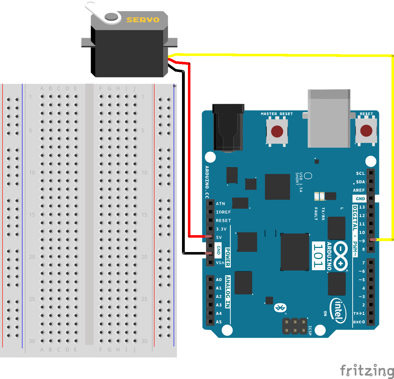
在本实验中,伺服马达通过红色导线获得 5V 电源,通过黑色导线接地,而白色导线连接到一个可以对其使用 PWM 的数字 GPIO 针脚(101 开发板上的 9、6、5、3)。
硬件接线
是否准备好开始对每个部件进行接线?请查看下面的接线图以了解如何连接每个部件。
| 极化组件 | 请特别注意组件用于指示如何在实验电路板上放置它的标记。极化组件只能按一个方向连接到电路。 |
将 3 根跳线连接到伺服马达的 3 针外接头上。这样可更轻松地将实验电路板与伺服马达相连。
实验的接线图
打开草图
在计算机上打开 Arduino IDE 软件。采用 Arduino 语言进行编码可控制电路。通过访问您先前下载并置于“示例”文件夹中的“101 SIK 指南代码”,来打开用于电路 10 的代码。
要打开该代码,请转到:文件 > 示例 > 101 SIK 指南代码 > Circuit_10
还可以将以下代码复制并粘贴到 Arduino IDE 中。点击“上传”,然后查看发生的情况!
language:cpp
/*
SparkFun Inventor's Kit
Example sketch 10

SINGLE SERVO

  Sweep a servo back and forth through its full range of motion.

This sketch was written by SparkFun Electronics,
with lots of help from the Arduino community.
This code is completely free for any use.
Visit http://learn.sparkfun.com/products/2 for SIK information.
Visit http://www.arduino.cc to learn more about Arduino.
*/

//include the servo library
#include

//create a servo object called servo1
Servo servo1;

void setup()
{
  //attach servo1 to pin 9 on the Arduino 101
  servo1.attach(9);
}

void loop()
{
  //create a local variable to store the servo's position.
  int position;

  // To control a servo, you give it the angle you'd like it
  // to turn to. Servos cannot turn a full 360 degrees, but you
  // can tell it to move anywhere between 0 and 180 degrees.

  // Change position at full speed:

  // Tell servo to go to 90 degrees
  servo1.write(90);

  // Pause to get it time to move
  delay(1000);

  // Tell servo to go to 180 degrees
  servo1.write(180);

  // Pause to get it time to move
  delay(1000);

  // Tell servo to go to 0 degrees
  servo1.write(0);

  // Pause to get it time to move
  delay(1000);

  // Tell servo to go to 180 degrees, stepping by two degrees
  for(position = 0; position < 180; position += 2)
  {
  // Move to next position
    servo1.write(position);
     // Short pause to allow it to move
    delay(20);
  }

  // Tell servo to go to 0 degrees, stepping by one degree
  for(position = 180; position >= 0; position -= 1)
  {
    // Move to next position
    servo1.write(position);
    // Short pause to allow it to move
    delay(20);
  }
}
要注意的代码
#include
#include 是特殊的“预处理器”命令,它在草图中插入库(或任何其他文件)。您可以自己键入此命令,也可以从“草图/导入库”菜单中选择已安装的库。
Servo servo1;
使用某个库时,您会创建该库的对象并进行命名。此对象是伺服马达库对象,会命名为 servo1。如果您使用多个伺服马达,则会采用这种方式命名每个伺服马达。
servo1.attach(9);
伺服马达库会添加使您可以控制伺服马达的新命令。要准备好 Arduino 以控制伺服马达,必须首先为每个伺服马达创建一个伺服马达“对象”(我们在此处将它命名为“servo1”),然后将它“连接”到一个数字针脚(我们在此处使用针脚 9)。可将此视为伺服马达调用 pinMode() 函数的方式。
servo1.write(180);
此工具包中的伺服马达并不会一直旋转,而是可以命令它们移动到特定位置。我们使用伺服马达库的 write() 命令将伺服马达移动到指定度数(0 至 180)。请记住,伺服马达需要时间进行移动,因此请在必要时向它提供短暂的 delay()。
应看到的情况
您应看到伺服马达按不同速度移动到各位置。如果马达未移动,请检查连接并确保已验证并上传了代码,或查看“故障诊断”部分。
故障诊断
伺服马达未旋转
即使采用了彩色导线,仍然非常容易将伺服马达插反。这里可能就是这种情况。
仍未运行
我们偶尔犯过以下错误:仅仅只是忘记将电源(红色和黑色导线)连接到 5 伏和接地 (GND)。
断续运行
如果伺服马达开始移动,然后抽动,并且 101 开发板上有一个指示灯闪烁,则可能是供电不够。使用墙上适配器(而不是 USB)应该可解决此问题。
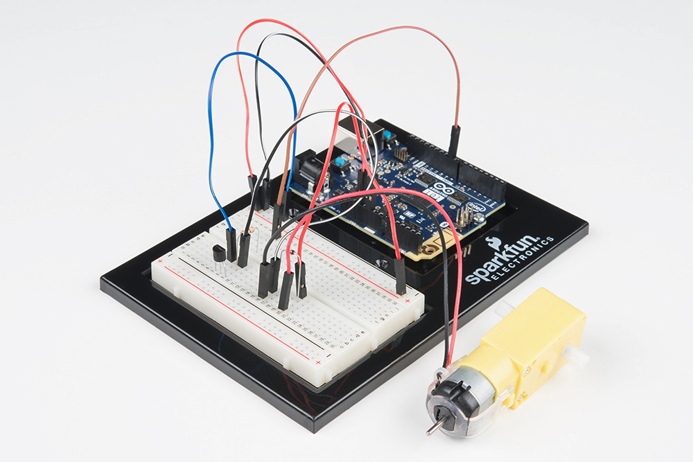
实验 11:使用晶体管
简介
在前面的实验中,您使用了伺服马达。现在,我们将处理马达旋转问题。这需要使用晶体管,它可以切换的电流量比 101 开发板更大。您将使用晶体管打开和关闭马达 -- 是的,一个闪烁的马达!
所需部件
您需要以下部件:
- 1x 实验电路板
- 1x Arduino 101 或 Genuino 101 开发板
- 1x 48:1 比率齿轮马达
- 1x 100Ω 电阻
- 1x NPN 晶体管
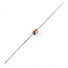
- 1x 二极管 1N4148
- 7x 跳线
没有 SIK?
如果您要执行本实验,但又没有 SIK,那么我们建议您使用这些部件:
Zener Diode - 5.1V 1W
COM-10301
您还需要一个 Arduino 101 或 Genuino 101 开发板。
Arduino 101
DEV-13787
Genuino 101
DEV-13984推荐阅读
继续进行本实验之前,我们建议您熟悉以下教程中的概念:
晶体管简介
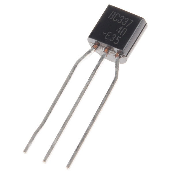
晶体管可以描述为小型电子开关。它使您可以通过较小电流控制较大电流负载,而不必承担烧坏敏感组件的风险。晶体管具有三个针脚:集电极、发射极和基极。电流只能按一个方向流到晶体管中 -- 流经集电极并从发射极流出。要控制电流的流动,您需要向基极施加小量电流。这一小电流可以是数字属性(开或关)或模拟属性(通过使用 PWM 和 analogWrite() 函数)。较大电流将随较小电流的变化而相应变化。
硬件接线
是否准备好开始对每个部件进行接线?请查看下面的接线图以了解如何连接每个部件。
| 极化组件 | 请特别注意组件用于指示如何在实验电路板上放置它的标记。极化组件只能按一个方向连接到电路。 |
请注意:构建电路时,请注意不要混用晶体管和温度传感器;它们几乎是相同的。在晶体管主体上查找“P2N2222A”。
实验的接线图
什么是续流二极管?
当旋转马达突然关闭时,其内部的磁场会瓦解,从而生成电压峰值。这可能会损坏晶体管。为了防止出现这种情况,我们使用“续流二极管”,它可使电压峰值“绕过”晶体管。将具有带子的二极管一端(阴极)连接到 5V。将二极管的另一端(阳极)连接到马达上的黑色导线。
打开草图
在计算机上打开 Arduino IDE 软件。采用 Arduino 语言进行编码可控制电路。通过访问您先前下载并置于“示例”文件夹中的“101 SIK 指南代码”,来打开用于电路 11 的代码。
要打开该代码,请转到:文件 > 示例 > 101 SIK 指南代码 > Circuit_11
还可以将以下代码复制并粘贴到 Arduino IDE 中。点击“上传”,然后查看发生的情况!
language:cpp
/*
SparkFun Inventor's Kit
Example sketch 11

SPINNING A MOTOR

  Use a transistor to spin a motor at different speeds.

This sketch was written by SparkFun Electronics,
with lots of help from the Arduino community.
This code is completely free for any use.
Visit http://learn.sparkfun.com/products/2 for SIK information.
Visit http://www.arduino.cc to learn more about Arduino.
*/

// constant pin for the transistor connected to the motor
const int motorPin = 9;

void setup()
{
  //set motorPin as OUTPUT
  pinMode(motorPin, OUTPUT);
}

void loop()
{
  // Here we've used comments to disable some of the examples.
  // To try different things, uncomment one of the following lines
  // and comment the other ones. See the functions below to learn
  // what they do and how they work.

   motorOnThenOff();
  // motorOnThenOffWithSpeed();
  // motorAcceleration();
}

// This function turns the motor on and off like the blinking LED.
// Try different values to affect the timing.
void motorOnThenOff()
{
  // milliseconds to turn the motor on
  int onTime = 3000;
  // milliseconds to turn the motor off
  int offTime = 3000;

  // turn the motor on (full speed)
  digitalWrite(motorPin, HIGH);
  // delay for onTime milliseconds
  delay(onTime);
  // turn the motor off
  digitalWrite(motorPin, LOW);
  // delay for offTime milliseconds
  delay(offTime);
}

// This function alternates between two speeds.
// Try different values to affect the timing and speed.
void motorOnThenOffWithSpeed()
{
  // between 0 (stopped) and 255 (full speed)
  int Speed1 = 200;
   // milliseconds for speed 1
  int Time1 = 3000;

  // between 0 (stopped) and 255 (full speed)
  int Speed2 = 50;
  // milliseconds to turn the motor off
  int Time2 = 3000;

  // turns the motor On
  analogWrite(motorPin, Speed1);
  // delay for onTime milliseconds
  delay(Time1);
  // turns the motor Off
  analogWrite(motorPin, Speed2);
  // delay for offTime milliseconds
  delay(Time2);
}

// This function slowly accelerates the motor to full speed,
// then back down to zero.
void motorAcceleration()
{
  // milliseconds between each speed step
  int speed;
  int delayTime = 20;

  // accelerate the motor
  for(speed = 0; speed <= 255; speed++)
  {
    // set the new speed
    analogWrite(motorPin,speed);
    // delay between speed steps
    delay(delayTime);
  }

  // decelerate the motor
  for(speed = 255; speed >= 0; speed--)
  {
    // set the new speed
    analogWrite(motorPin,speed);
    // delay between speed steps
    delay(delayTime);
  }
}
应看到的情况
如果您正确装配了电路的组件,还验证/上传了正确代码,则直流马达应旋转。如果您的电路未运行,请查看“故障诊断”部分。
故障诊断
马达未旋转
如果您使用自己的晶体管,请按照数据表仔细检查引出线是否与所使用的晶体管兼容(许多情况并不兼容)。
仍未成功
如果您使用自己的马达,请仔细检查它是否适用于 5 伏,以及它是否没有消耗太多功率。
仍未运行
Arduino 有时会与计算机断开连接。尝试拔下它,然后重新插入 USB 端口。
实验 12:使用马达驱动器
简介
在前面的实验中,您使用了伺服马达。现在,我们将处理马达旋转问题。这需要使用晶体管,它可以切换的电流量比 101 开发板更大。您将使用晶体管打开和关闭马达 -- 是的,一个闪烁的马达!
所需部件
您需要以下部件:
- 1x 实验电路板
- 1x Arduino 101 或 Genuino 101 开发板
- 1x 48:1 比率齿轮马达
- 1x 100Ω 电阻
- 1x NPN 晶体管
- 1x 二极管 1N4148
- 7x 跳线
没有 SIK?
如果您要执行本实验,但又没有 SIK,那么我们建议您使用这些部件:
Zener Diode - 5.1V 1W
COM-10301
您还需要一个 Arduino 101 或 Genuino 101 开发板。
Arduino 101
DEV-13787
Genuino 101
DEV-13984推荐阅读
继续进行本实验之前,我们建议您熟悉以下教程中的概念:
晶体管简介
晶体管可以描述为小型电子开关。它使您可以通过较小电流控制较大电流负载,而不必承担烧坏敏感组件的风险。晶体管具有三个针脚:集电极、发射极和基极。电流只能按一个方向流到晶体管中 -- 流经集电极并从发射极流出。要控制电流的流动,您需要向基极施加小量电流。这一小电流可以是数字属性(开或关)或模拟属性(通过使用 PWM 和 analogWrite() 函数)。较大电流将随较小电流的变化而相应变化。
硬件接线
是否准备好开始对每个部件进行接线?请查看下面的接线图以了解如何连接每个部件。
| 极化组件 | 请特别注意组件用于指示如何在实验电路板上放置它的标记。极化组件只能按一个方向连接到电路。 |
请注意:构建电路时,请注意不要混用晶体管和温度传感器;它们几乎是相同的。在晶体管主体上查找“P2N2222A”。
实验的接线图
什么是续流二极管?
当旋转马达突然关闭时,其内部的磁场会瓦解,从而生成电压峰值。这可能会损坏晶体管。为了防止出现这种情况,我们使用“续流二极管”,它可使电压峰值“绕过”晶体管。将具有带子的二极管一端(阴极)连接到 5V。将二极管的另一端(阳极)连接到马达上的黑色导线。
打开草图
在计算机上打开 Arduino IDE 软件。采用 Arduino 语言进行编码可控制电路。通过访问您先前下载并置于“示例”文件夹中的“101 SIK 指南代码”,来打开用于电路 11 的代码。
要打开该代码,请转到:文件 > 示例 > 101 SIK 指南代码 > Circuit_11
还可以将以下代码复制并粘贴到 Arduino IDE 中。点击“上传”,然后查看发生的情况!
language:cpp
/*
SparkFun Inventor's Kit
Example sketch 11

SPINNING A MOTOR

  Use a transistor to spin a motor at different speeds.

This sketch was written by SparkFun Electronics,
with lots of help from the Arduino community.
This code is completely free for any use.
Visit http://learn.sparkfun.com/products/2 for SIK information.
Visit http://www.arduino.cc to learn more about Arduino.
*/

// constant pin for the transistor connected to the motor
const int motorPin = 9;

void setup()
{
  //set motorPin as OUTPUT
  pinMode(motorPin, OUTPUT);
}

void loop()
{
  // Here we've used comments to disable some of the examples.
  // To try different things, uncomment one of the following lines
  // and comment the other ones. See the functions below to learn
  // what they do and how they work.

   motorOnThenOff();
  // motorOnThenOffWithSpeed();
  // motorAcceleration();
}

// This function turns the motor on and off like the blinking LED.
// Try different values to affect the timing.
void motorOnThenOff()
{
  // milliseconds to turn the motor on
  int onTime = 3000;
  // milliseconds to turn the motor off
  int offTime = 3000;

  // turn the motor on (full speed)
  digitalWrite(motorPin, HIGH);
  // delay for onTime milliseconds
  delay(onTime);
  // turn the motor off
  digitalWrite(motorPin, LOW);
  // delay for offTime milliseconds
  delay(offTime);
}

// This function alternates between two speeds.
// Try different values to affect the timing and speed.
void motorOnThenOffWithSpeed()
{
  // between 0 (stopped) and 255 (full speed)
  int Speed1 = 200;
   // milliseconds for speed 1
  int Time1 = 3000;

  // between 0 (stopped) and 255 (full speed)
  int Speed2 = 50;
  // milliseconds to turn the motor off
  int Time2 = 3000;

  // turns the motor On
  analogWrite(motorPin, Speed1);
  // delay for onTime milliseconds
  delay(Time1);
  // turns the motor Off
  analogWrite(motorPin, Speed2);
  // delay for offTime milliseconds
  delay(Time2);
}

// This function slowly accelerates the motor to full speed,
// then back down to zero.
void motorAcceleration()
{
  // milliseconds between each speed step
  int speed;
  int delayTime = 20;

  // accelerate the motor
  for(speed = 0; speed <= 255; speed++)
  {
    // set the new speed
    analogWrite(motorPin,speed);
    // delay between speed steps
    delay(delayTime);
  }

  // decelerate the motor
  for(speed = 255; speed >= 0; speed--)
  {
    // set the new speed
    analogWrite(motorPin,speed);
    // delay between speed steps
    delay(delayTime);
  }
}
应看到的情况
如果您正确装配了电路的组件,还验证/上传了正确代码,则直流马达应旋转。如果您的电路未运行,请查看“故障诊断”部分。
故障诊断
马达未旋转
如果您使用自己的晶体管,请按照数据表仔细检查引出线是否与所使用的晶体管兼容(许多情况并不兼容)。
仍未成功
如果您使用自己的马达,请仔细检查它是否适用于 5 伏,以及它是否没有消耗太多功率。
仍未运行
Arduino 有时会与计算机断开连接。尝试拔下它,然后重新插入 USB 端口。
实验 13:马达驱动器和输入
简介
在实验 12 中,您使用了马达驱动器板来控制马达的方向和速度。问题在于您必须对马达的方向和速度进行硬编码。使用马达的大多数应用都允许用户控制马达的速度和方向,这非常类似于您操纵自己的汽车。在本实验中,我们将添加两个输入并使用它们控制马达的方向和速度。
您是否准备好运行您的马达了?让我们开始吧!
所需部件
您需要以下部件:
- 1x 实验电路板
- 1x Arduino 101 或 Genuino 101 开发板
- 1x SPDT 开关
- 1x 10K 电位计
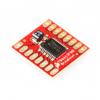
- 1x SparkFun 马达驱动器板
- 1x 48:1 比率齿轮马达
- 20x 跳线
没有 SIK?
如果您要执行本实验,但又没有 SIK,那么我们建议您使用这些部件:
您还需要一个 Arduino 101 或 Genuino 101 开发板。
Arduino 101
DEV-13787
Genuino 101
DEV-13984硬件接线
是否准备好开始对每个部件进行接线?请查看下面的接线图以了解如何连接每个部件。
| 极化组件 | 请特别注意组件用于指示如何在实验电路板上放置它的标记。极化组件只能按一个方向连接到电路。 |
实验的接线图

打开草图
在计算机上打开 Arduino IDE 软件。采用 Arduino 语言进行编码可控制电路。通过访问您先前下载并置于“示例”文件夹中的“SIK 指南代码”,来打开用于电路 13 的代码。
要打开该代码,请转到:文件 > 示例 > SIK 指南代码 > Circuit_13
还可以将以下代码复制并粘贴到 Arduino IDE 中。点击“上传”,然后查看发生的情况!
language:cpp
/*
SparkFun Inventor's Kit
Example sketch 13

SparkFun Motor Controller with Inputs

  Use the inputs to manually set the direction and speed of a motor.

This sketch was written by SparkFun Electronics,
with lots of help from the Arduino community.
This code is completely free for any use.
Visit http://learn.sparkfun.com/products/2 for SIK information.
Visit http://www.arduino.cc to learn more about Arduino.
*/
 //define the two direction logic pins and the speed / PWM pin
 const int DIR_A = 5;
 const int DIR_B = 4;
 const int PWM = 6;

 //define the input pins
 const int switchPin = 10;
 const int potPin = 0;

 void setup()
 {
  //set all pins as output
  pinMode(DIR_A, OUTPUT);
  pinMode(DIR_B, OUTPUT);
  pinMode(PWM, OUTPUT);
  //set the switchPin as INPUT
  pinMode(switchPin, INPUT);
  }

void loop()
{
//read the value from the potentiometer and divide
//it by 4 to get a 0-255 range. Store the value in
//the speed variable
int speed = analogRead(potPin) / 4;

 //read the value of the switch and store it in the
 //direction variable.

//if the value of direction is HIGH drive forward at
//a speed set by the speed variable, else drive reverse
//at a speed set by the speed variable.
if (digitalRead(switchPin) == HIGH)
{
  forward(speed);
}
else
 {
 reverse(speed);
 }
}

//create a custom function that defines moving forward
//the forward() function accepts one parameter and that is
//the speed at which you want to drive forward (0-255)
 void forward(int spd)
 {
 //motor contoller direction pins set to forward
 digitalWrite(DIR_A, HIGH);
 digitalWrite(DIR_B, LOW);

  //write the speed by using the parameter of spd
 analogWrite(PWM, spd);
  }

//create a custom function that defines moving in reverse
//the reverse() function accepts one parameter and that is
//the speed at which you want to drive in reverse (0-255)
void reverse(int spd)
{
//set motor controller pins to reverse
digitalWrite(DIR_A, LOW);
digitalWrite(DIR_B, HIGH);

 //write the speed by using the parameter of spd
 analogWrite(PWM, spd);
 }
这些可怕的大型函数采用单个值作为参数:速度。每个函数因而接受该值并将它应用于 analogWrite() 函数(而不是自定义函数)。自定义函数是清理代码的好方法,还可使它更加模块化并且可用于其他应用。请注意!您正在编写自己的库。
应看到的情况
您应能够通过反转 SPDT 开关来控制马达的方向,随后可通过电位计控制速度。继续进行并尝试调整两个输入以确保它们都运行正常并且马达响应这些输入。

故障诊断
马达只按一个方向旋转
仔细检查开关的接线,还要仔细检查 if() 语句以确保该语句后面没有分号。
此外,仔细检查以确保对待机针脚进行了正确接线(连接到 3.3V)。
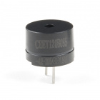
实验 14:使用压电式蜂鸣器
简介
在本实验中,我们将再次跨越数字世界与模拟世界之间的鸿沟。我们将使用一个压电式蜂鸣器,它会在您对它施加电压时发出小的“咔哒”声(尝试一下!)。这本身并不非常令人兴奋,但是如果您每秒打开和关闭电压数百次,则压电式蜂鸣器会发出某种音调。并且如果您将一系列音调串在一起,那么您便可创作出音乐!此电路和草图将发出一种经典音调。我们绝不会令您失望!
我们还添加了一个与蜂鸣器串联的按钮。为什么?因为每个好的声音生成器都需要一个静音按钮!要听到使用蜂鸣器从 101 开发板播放的歌曲,您需要按下按钮不放。要使蜂鸣器静音,只需松开按钮。
所需部件
您需要以下部件:
- 1x 实验电路板
- 1x Arduino 101 或 Genuino 101 开发板
- 1x 压电式蜂鸣器
- 1x 按钮
- 5x 跳线
没有 SIK?
如果您要执行本实验,但又没有 SIK,那么我们建议您使用这些部件:
您还需要一个 Arduino 101 或 Genuino 101 开发板。
Arduino 101
DEV-13787
Genuino 101
DEV-13984压电式蜂鸣器简介

蜂鸣器是一个小型组件,其中有一片会在您对它施加电压时移动的金属。这种运动会产生小声音,或“咔哒”声。如果您打开和关闭电压的速度足够快,则会听到不同的蜂鸣声、尖叫声、唧唧声和嗡嗡声。您将使用 PWM 控制打开和关闭压电的速度 -- 进而控制从蜂鸣器发出的音频频率。通过调整 PWM 可以从蜂鸣器发出合理音符。
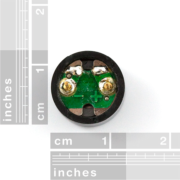
如果翻转蜂鸣器并查看底部,则您会看到一个针脚旁具有 (+)。该针脚连接到从 PWM 针脚发出的信号。另一个针脚应接地。
硬件接线
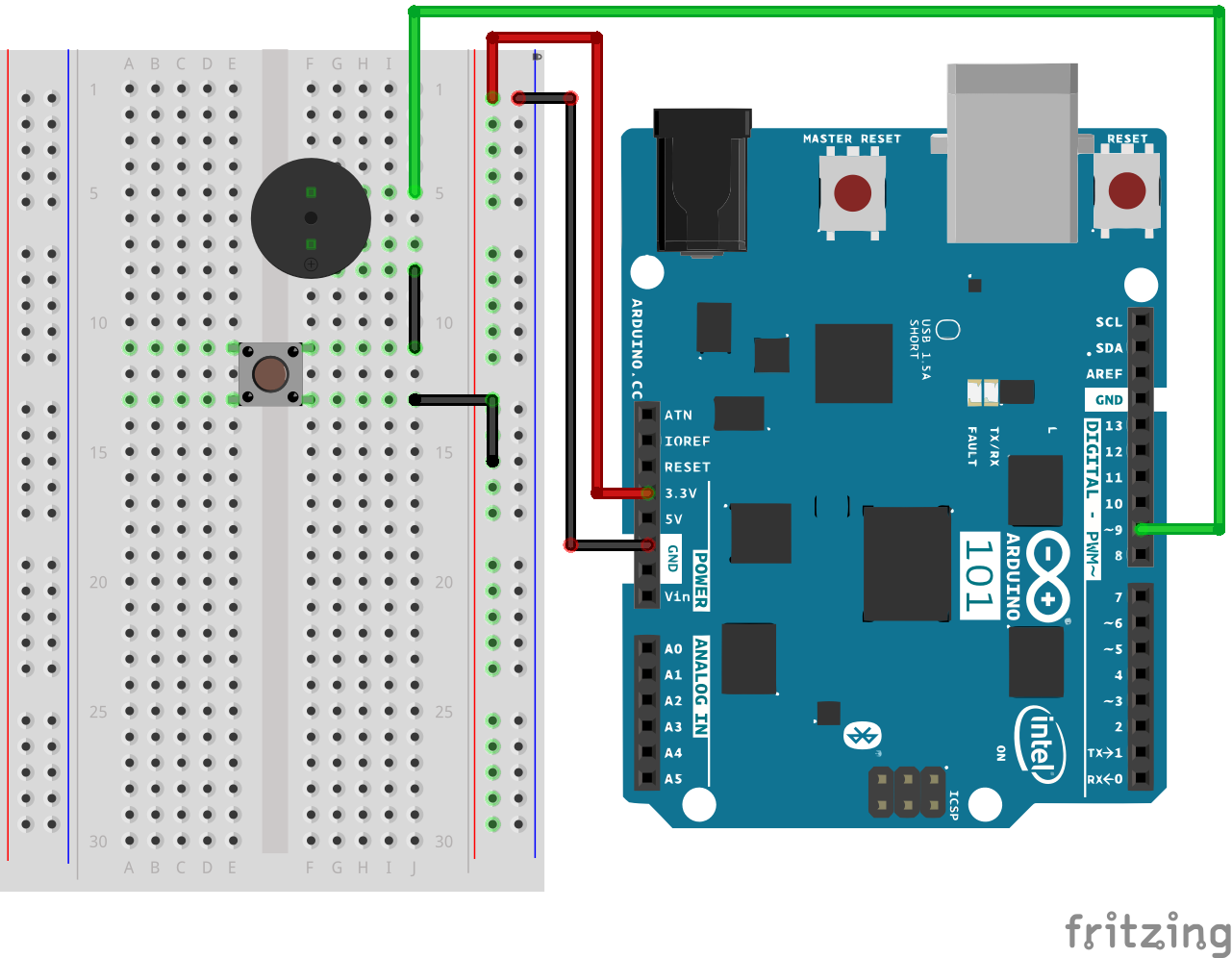
是否准备好开始对每个部件进行接线?请查看下面的接线图以了解如何连接每个部件。
| 极化组件 | 请特别注意组件用于指示如何在实验电路板上放置它的标记。极化组件只能按一个方向连接到电路。 |
实验的接线图
打开草图
在计算机上打开 Arduino IDE 软件。采用 Arduino 语言进行编码可控制电路。通过访问您先前下载并置于“示例”文件夹中的“101 SIK 指南代码”,来打开用于电路 14 的代码。
要打开该代码,请转到:文件 > 示例 > SIK 指南代码 > Circuit_14
还可以将以下代码复制并粘贴到 Arduino IDE 中。点击“上传”,然后查看发生的情况!
language:cpp
/*
SparkFun Inventor's Kit
Example sketch 14

BUZZER

  Use the buzzer to play a song!

This sketch was written by SparkFun Electronics,
with lots of help from the Arduino community.
(This sketch was originally developed by D. Cuartielles for K3)
This code is completely free for any use.
Visit http://learn.sparkfun.com/products/2 for SIK information.
Visit http://www.arduino.cc to learn more about Arduino.

*/

/*
This sketch uses the buzzer to play songs.
The Arduino's tone() command will play notes of a given frequency.
We'll provide a function that takes in note characters (a-g),
and returns the corresponding frequency from this table:

  note  frequency
  c     262 Hz
  d     294 Hz
  e     330 Hz
  f     349 Hz
  g     392 Hz
  a     440 Hz
  b     494 Hz
  C     523 Hz

For more information, see http://arduino.cc/en/Tutorial/Tone
*/

const int buzzerPin = 9;

// We'll set up an array with the notes we want to play
// change these values to make different songs!

// Length must equal the total number of notes and spaces

const int songLength = 18;

// Notes is an array of text characters corresponding to the notes
// in your song. A space represents a rest (no tone)

char notes[] = "cdfda ag cdfdg gf "; // a space represents a rest

// Beats is an array of values for each note and rest.
// A "1" represents a quarter-note, 2 a half-note, etc.
// Don't forget that the rests (spaces) need a length as well.

int beats[] = {1,1,1,1,1,1,4,4,2,1,1,1,1,1,1,4,4,2};

// The tempo is how fast to play the song.
// To make the song play faster, decrease this value.

int tempo = 150;

void setup()
{
  pinMode(buzzerPin, OUTPUT);
}

void loop()
{
  int i, duration;

  for (i = 0; i < songLength; i++) // step through the song arrays
  {
    duration = beats[i] * tempo;  // length of note/rest in ms

    if (notes[i] == ' ')          // is this a rest?
    {
      delay(duration);            // then pause for a moment
    }
    else                          // otherwise, play the note
    {
      tone(buzzerPin, frequency(notes[i]), duration);
      delay(duration);            // wait for tone to finish
    }
    delay(tempo/10);              // brief pause between notes
  }

  // We only want to play the song once, so we'll pause forever:
  while(true){}
  // If you'd like your song to play over and over,
  // remove the above statement
}

int frequency(char note)
{
  // This function takes a note character (a-g), and returns the
  // corresponding frequency in Hz for the tone() function.

  int i;
  const int numNotes = 8;  // number of notes we're storing

  // The following arrays hold the note characters and their
  // corresponding frequencies. The last "C" note is uppercase
  // to separate it from the first lowercase "c". If you want to
  // add more notes, you'll need to use unique characters.

  // For the "char" (character) type, we put single characters
  // in single quotes.

  char names[] = { 'c', 'd', 'e', 'f', 'g', 'a', 'b', 'C' };
  int frequencies[] = {262, 294, 330, 349, 392, 440, 494, 523};

  // Now we'll search through the letters in the array, and if
  // we find it, we'll return the frequency for that note.

  for (i = 0; i < numNotes; i++)  // Step through the notes
  {
    if (names[i] == note)         // Is this the one?
    {
      return(frequencies[i]);     // Yes! Return the frequency
    }
  }
  return(0);  // We looked through everything and didn't find it,
              // but we still need to return a value, so return 0.
}
要注意的代码
char notes[] = "cdfda ag cdfdg gf ";
char names[] = {'c','d','e','f','g','a','b','C'};
到目前为止,我们只处理了数值数据,但是 Arduino 还可以处理文本。字符(单个、可打印、字母、数字和其他符号)具有自己的类型,称为“char”。使用字符数组时,可以在双引号之间进行定义(也称为“字符串”),或是定义为单引号字符的列表。
tone(pin, frequency, duration);
Arduino 有许多有用的内置命令,其中一个是 tone() 函数。此函数按特定频率驱动输出针脚,从而十分适合于驱动蜂鸣器和扬声器。如果您为它提供持续时间(以毫秒为单位),则它会播放音调,然后停止。如果您没有为它提供持续时间,则它会永远保持播放音调(但是您可以使用另一个函数 noTone() 停止它)。
应看到的情况
应看到的情况 -- 好吧,看不到任何情况!应听到的声音 -- 好吧,一开始什么也听不到!但是如果您在草图完成上传之后立即按下按钮不放,则您应该能够听到歌曲。如果您在中途听到歌曲或是感觉它似乎未在播放,请按重置按钮,然后按下按钮。
如果它未运行,请确保正确装配了电路以及验证了代码并将它上传到开发板,或查看“故障诊断”部分。
故障诊断
无声音
由于压电蜂鸣器的大小和形状特点,您可能容易错过实验电路板上的正确孔。尝试仔细检查其位置。
此外,仔细检查以确保按钮的接线正确。如果其接线错误,则无论您是否按下按钮,电路都绝不会完整。
似乎只播放了歌曲的一部分
当您按住按钮时,您可能只听到了歌曲的一部分。要再次开始歌曲,请在按下静音按钮不放的同时,按 101 开发板上的“主重置”按钮。
感觉失望
代码的编写方式能让您方便地添加自己的歌曲。前进吧,摇滚起来!
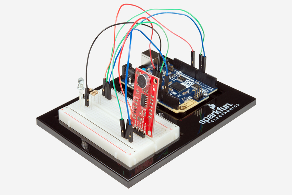
实验 15:使用声音探测器板
简介
您在前面的实验中已使用了一些不同的模拟输入。在本实验中,您会将声音作为输入,并使用 SparkFun 声音探测器板。您将使用该板上的“封包”输出来测量声音在房间中的响度,然后使用一些称为 switch case 语句的精致代码来相应地更改颜色和 RGB。
我们将此称为娱乐仪表!如果局面失控,您会看到红色!
所需部件
您需要以下部件:
- 1x 实验电路板
- 1x Arduino 101 或 Genuino 101 开发板
- 3x 100Ω 电阻
- 1x 共阴极 RGB LED
- 1x SparkFun 声音探测器板
- 9x 跳线
没有 SIK?
如果您要执行本实验,但又没有 SIK,那么我们建议您使用这些部件:
您还需要一个 Arduino 101 或 Genuino 101 开发板。
Arduino 101
DEV-13787
Genuino 101
DEV-13984推荐阅读
继续进行本实验之前,我们建议您熟悉以下教程中的概念:
声音探测器板指南

声音探测器板是精致的小型传感器!它是可使您省下大量接线的麦克风电路。将该板通过 VCC 针脚连接到电源 (3.3V),并通过 GND 针脚接地之后,您可通过三个选项将不同信号用作 101 板的输入。
第一个信号 GATE 是数字信号,会在环境声音越过特定阈值时打开。GATE 还在声音探测器上接线到一个 LED。对它正确加电并发出声音之后,您会看到红色 LED 在声音“响亮”时亮起,在声音“安静”时熄灭。
第二个信号 ENVELOPE 将幅度(声音的响度)按比例调整为 0-1023 的 10 位值。在安静的起居室中,此级别大约登记为 10。
最后一个信号是原始 AUDIO 信号。在安静的房间中,信号级别大约为 512,并将基于环境声音的频率生成波形曲线。如果您希望进行一些超出此指南范围的音频处理,则需要使用原始 AUDIO 信号。如需了解有关声音探测器板的细节的更多信息,请查看我们的接线指南。
硬件接线
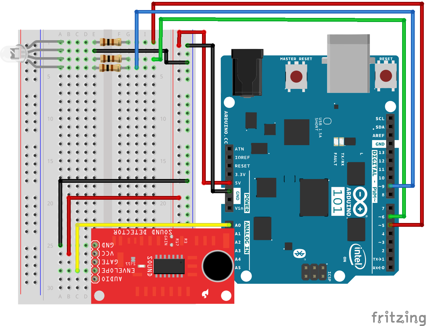
是否准备好开始对每个部件进行接线?请查看下面的接线图以了解如何连接每个部件。
| 极化组件 | 请特别注意组件用于指示如何在实验电路板上放置它的标记。极化组件只能按一个方向连接到电路。 |
实验的接线图
打开草图
在计算机上打开 Arduino IDE 软件。采用 Arduino 语言进行编码可控制电路。通过访问您先前下载并置于“示例”文件夹中的“101 SIK 指南代码”,来打开用于电路 15 的代码。
要打开该代码,请转到:文件 > 示例 > 101 SIK 指南代码 > Circuit_15
还可以将以下代码复制并粘贴到 Arduino IDE 中。点击“上传”,然后查看发生的情况!
language:cpp
/*
SparkFun Inventor's Kit
Example sketch 15

SOUND DETECTOR

Use the sound detector to measure the volume of the surrounding area and change the
color of an RGB based on that volume.

 //pin variables
const int redPin = 5;
const int greenPin = 6;
const int bluePin = 9;
const int soundPin = 0;

//variables for storing raw sound and scaled value
int sound;
int scale;

void setup()
{
 //start the serial port a@ 9600bps
 Serial.begin(9600);
 //set RGB pins to OUTPUT
 pinMode(redPin, OUTPUT);
 pinMode(greenPin, OUTPUT);
 pinMode(bluePin, OUTPUT);
}

void loop()
{
 //read and store the audio from Envelope pin
 sound = analogRead(soundPin);
 //map sound which in a quiet room a clap is 300
 //from 0 to 3 to be used with switch case
 scale = map(sound, 0, 300, 0, 3);

 //print values over the serial port for debugging
 Serial.print(sound);
 Serial.print("   ");
 Serial.println(scale);

 //switch case on scaled value
switch (scale)
{
//if 0 RGB = Blue
case 0:
  digitalWrite(redPin, LOW);
  digitalWrite(greenPin, LOW);
  digitalWrite(bluePin, HIGH);
  break;
//if 1 RGB = Green
case 1:
  digitalWrite(redPin, LOW);
  digitalWrite(greenPin, HIGH);
  digitalWrite(bluePin, LOW);
  break;
//if 2 RGB = Yellow
case 2:
  digitalWrite(redPin, HIGH);
  digitalWrite(greenPin, HIGH);
  digitalWrite(bluePin, LOW);
  break;
//if 3 RGB = Red
case 3:
  digitalWrite(redPin, HIGH);
  digitalWrite(greenPin, LOW);
  digitalWrite(bluePin, LOW);
  break;
//default off
default:
  digitalWrite(redPin, LOW);
  digitalWrite(greenPin, LOW);
  digitalWrite(bluePin, LOW);
  break;
 }
}
要注意的代码
scale = map(sound,0,300,0,3
这可能类似于值的奇怪映射。这是针对使用 switch case 语句的设置,我们需要将大型值集合映射到三到四个选择。映射函数采用两种方式运行,但是它在构建与 switch case 语句配对的值的范围时是最方便的。
switch(value)
{
 case(0):
 //do something
 break;
 case(1):
 //do something else
 break;
 default:
 //do another thing
 break;
}
当您在尝试基于一系列值执行操作,并认为自己需要很长一串 if else() 语句时,switch case 语句会非常方便。Switch() 会查看一个变量,然后在情况列表中查找其匹配项。如果不存在匹配项,则它使用默认设置。每种情况还具有自己的中断命令,这使 Arduino 可以从 switch case 语句中退出并继续执行。
应看到的情况
代码上传并且草图启动之后,RGB 应变为蓝色。发出大量声音,RGB 应从蓝色变为绿色,然后变为黄色... 如果声音确实很大,它可能会变为红色!不要担心;我们并不会报警!
故障诊断
没有变为黄色或红色
打开串行监视器以进行一些调试。检查安静值,然后发出一连串声音。调整映射函数以确保范围相同。
声音探测器传出奇怪的值
确保将声音探测器板接线到 3.3V,并且您在读取“封包”针脚。
仍未运行
Arduino 101 开发板有时会与计算机断开连接。尝试拔下它,然后重新插入 USB 端口。
实验 16:使用移位寄存器
简介
现在我们将步入原始 IC(集成电路)的世界。在本实验中,您将了解有关使用移位寄存器的所有信息。移位寄存器会为 101 开发板提供额外八个输出(仅使用板上的三个针脚)。对于本实验,您将练习使用移位寄存器控制八个 LED。是的 -- 比实验 4 还要多两个 LED!
所需部件
您需要以下部件:
- 1x 实验电路板
- 1x Arduino 101 或 Genuino 101 开发板
- 8x LED
- 8x 330Ω 电阻
- 1x 移位寄存器 8 位 - 74HC595
- 19x 跳线
没有 SIK?
如果您要执行本实验,但又没有 SIK,那么我们建议您使用这些部件:
您还需要一个 Arduino 101 或 Genuino 101 开发板。
Arduino 101
DEV-13787
Genuino 101
DEV-13984推荐阅读
继续进行本实验之前,我们建议您熟悉以下教程中的概念:
移位寄存器简介
移位寄存器是一种集成电路 (IC)。IC 是由流行且常用的电路组成的微型塑料密封包。IC 充当单个组件,可执行特定作业功能,简化了过去曾经耗费大量时间和空间的电路设计。
移位寄存器本质上使您可以控制最多八个输出,同时仅使用 101 板上的三个针脚。与实验 4(在其中将六个针脚用于六个单独输出)相比,它使您可以通过更少的针脚控制更多的输出。
可这样理解:进入移位寄存器的数据类似于一列具有八个不同车厢的火车。如果车厢装满货物,则它表示的数据是 1。如果火车车厢为空,则它表示的数据是 0。当整列火车都进入移位寄存器时,它会分解,每个车厢都位于自己的轨道上。这些轨道可以转换为移位寄存器的八个输出针脚。如果车厢已满 (1),则它所处的针脚会上拉为 HIGH;如果车厢为空 (0),则针脚会下拉为 LOW。如果您在火车进入移位寄存器之后不断发送火车,则可以使 LED 呈现动态或控制类似于 7 段显示器的设备来倒计数,甚至是在不同时间转动的大量马达。只需向移位寄存器发送具有不同 1 和 0 模式的火车,即可实现所有这些目标。
如需了解有关火车移位寄存器的更多信息,请查看我们的移位寄存器教程。
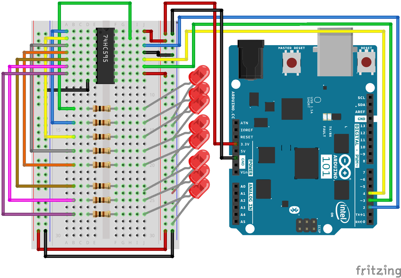
硬件接线
是否准备好开始对每个部件进行接线?请查看下面的接线图以了解如何连接每个部件。
| 极化组件 | 请特别注意组件用于指示如何在实验电路板上放置它的标记。极化组件只能按一个方向连接到电路。 |
实验的接线图
打开草图
在计算机上打开 Arduino IDE 软件。采用 Arduino 语言进行编码可控制电路。通过访问您先前下载并置于“示例”文件夹中的“101 SIK 指南代码”,来打开用于电路 16 的代码。
要打开该代码,请转到:文件 > 示例 > 101 SIK 指南代码 > Circuit_16
还可以将以下代码复制并粘贴到 Arduino IDE 中。点击“上传”,然后查看发生的情况!
language:cpp
/*
SparkFun Inventor's Kit
Example sketch 16

SHIFT REGISTER

  Use a shift register to turn three pins into eight (or more!)
  outputs

This sketch was written by SparkFun Electronics,
with lots of help from the Arduino community.
This code is completely free for any use.
Visit http://learn.sparkfun.com/products/2 for SIK information.
Visit http://www.arduino.cc to learn more about Arduino.
*/

// Pin definitions:
// The 74HC595 uses a type of serial connection called SPI
// (Serial Peripheral Interface) that requires three pins:

int datapin = 2;
int clockpin = 3;
int latchpin = 4;

// We'll also declare a global variable for the data we're
// sending to the shift register:

byte data = 0;

void setup()
{
  // Set the three SPI pins to be outputs:

  pinMode(datapin, OUTPUT);
  pinMode(clockpin, OUTPUT);
  pinMode(latchpin, OUTPUT);
}

void loop()
{
  // We're going to use the same functions we played with back
  // in circuit 04, "Multiple LEDs," we've just replaced
  // digitalWrite() with a new function called shiftWrite()
  // (see below). We also have a new function that demonstrates
  // binary counting.

  // To try the different functions below, uncomment the one
  // you want to run, and comment out the remaining ones to
  // disable them from running.

  oneAfterAnother();      // All on, all off

  //oneOnAtATime();       // Scroll down the line

  //pingPong();           // Like above, but back and forth

  //randomLED();          // Blink random LEDs

  //marquee();

  //binaryCount();        // Bit patterns from 0 to 255
}

void shiftWrite(int desiredPin, boolean desiredState)

// This function lets you make the shift register outputs
// HIGH or LOW in exactly the same way that you use digitalWrite().

// Like digitalWrite(), this function takes two parameters:

//    "desiredPin" is the shift register output pin
//    you want to affect (0-7)

//    "desiredState" is whether you want that output
//    to be HIGH or LOW

// Inside the Arduino, numbers are stored as arrays of "bits,"
// each of which is a single 1 or 0 value. Because a "byte" type
// is also eight bits, we'll use a byte (which we named "data"
// at the top of this sketch) to send data to the shift register.
// If a bit in the byte is "1," the output will be HIGH. If the bit
// is "0," the output will be LOW.

// To turn the individual bits in "data" on and off, we'll use
// a new Arduino commands called bitWrite(), which can make
// individual bits in a number 1 or 0.
{
  // First we'll alter the global variable "data," changing the
  // desired bit to 1 or 0:

  bitWrite(data,desiredPin,desiredState);

  // Now we'll actually send that data to the shift register.
  // The shiftOut() function does all the hard work of
  // manipulating the data and clock pins to move the data
  // into the shift register:

  shiftOut(datapin, clockpin, MSBFIRST, data);

  // Once the data is in the shift register, we still need to
  // make it appear at the outputs. We'll toggle the state of
  // the latchPin, which will signal the shift register to "latch"
  // the data to the outputs. (Latch activates on the high-to
  // -low transition).

  digitalWrite(latchpin, HIGH);
  digitalWrite(latchpin, LOW);
}

/*
oneAfterAnother()

This function will light one LED, delay for delayTime, then light
the next LED, and repeat until all the LEDs are on. It will then
turn them off in the reverse order.
*/

void oneAfterAnother()
{
  int index;
  int delayTime = 100; // Time (milliseconds) to pause between LEDs
                       // Make this smaller for faster switching

  // Turn all the LEDs on:

  // This for() loop will step index from 0 to 7
  // (putting "++" after a variable means add one to it)
  // and will then use digitalWrite() to turn that LED on.

  for(index = 0; index <= 7; index++)
  {
    shiftWrite(index, HIGH);
    delay(delayTime);
  }

  // Turn all the LEDs off:

  // This for() loop will step index from 7 to 0
  // (putting "--" after a variable means subtract one from it)
  // and will then use digitalWrite() to turn that LED off.

  for(index = 7; index >= 0; index--)
  {
    shiftWrite(index, LOW);
    delay(delayTime);
  }
}

/*
oneOnAtATime()

This function will step through the LEDs, lighting one at at time.
*/

void oneOnAtATime()
{
  int index;
  int delayTime = 100; // Time (milliseconds) to pause between LEDs
                       // Make this smaller for faster switching

  // step through the LEDs, from 0 to 7

  for(index = 0; index <= 7; index++)
  {
    shiftWrite(index, HIGH);    // turn LED on
    delay(delayTime);       // pause to slow down the sequence
    shiftWrite(index, LOW); // turn LED off
  }
}

/*
pingPong()

This function will step through the LEDs, lighting one at at time,
in both directions.
*/

void pingPong()
{
  int index;
  int delayTime = 100; // time (milliseconds) to pause between LEDs
                       // make this smaller for faster switching

  // step through the LEDs, from 0 to 7

  for(index = 0; index <= 7; index++)
  {
    shiftWrite(index, HIGH);    // turn LED on
    delay(delayTime);       // pause to slow down the sequence
    shiftWrite(index, LOW); // turn LED off
  }

  // step through the LEDs, from 7 to 0

  for(index = 7; index >= 0; index--)
  {
    shiftWrite(index, HIGH);    // turn LED on
    delay(delayTime);       // pause to slow down the sequence
    shiftWrite(index, LOW); // turn LED off
  }
}

/*
randomLED()

This function will turn on random LEDs. Can you modify it so it
also lights them for random times?
*/

void randomLED()
{
  int index;
  int delayTime = 100; // time (milliseconds) to pause between LEDs
                       // make this smaller for faster switching

  // The random() function will return a semi-random number each
  // time it is called. See http://arduino.cc/en/Reference/Random
  // for tips on how to make random() more random.

  index = random(8);    // pick a random number between 0 and 7

  shiftWrite(index, HIGH);  // turn LED on
  delay(delayTime);     // pause to slow down the sequence
  shiftWrite(index, LOW);   // turn LED off
}

/*
marquee()

This function will mimic "chase lights" like those around signs.
*/

void marquee()
{
  int index;
  int delayTime = 200; // Time (milliseconds) to pause between LEDs
                       // Make this smaller for faster switching

  // Step through the first four LEDs
  // (We'll light up one in the lower 4 and one in the upper 4)

  for(index = 0; index <= 3; index++)
  {
    shiftWrite(index, HIGH);    // Turn a LED on
    shiftWrite(index+4, HIGH);  // Skip four, and turn that LED on
    delay(delayTime);       // Pause to slow down the sequence
    shiftWrite(index, LOW); // Turn both LEDs off
    shiftWrite(index+4, LOW);
  }
}

/*
binaryCount()

Numbers are stored internally in the Arduino as arrays of "bits,"
each of which is a 1 or 0\. Just like the base-10 numbers we use
every day, The position of the bit affects the magnitude of its
contribution to the total number:

Bit position   Contribution
0              1
1              2
2              4
3              8
4              16
5              32
6              64
7              128

To build any number from 0 to 255 from the above 8 bits, just
select the contributions you need to make. The bits will then be
1 if you use that contribution, and 0 if you don't.

This function will increment the "data" variable from 0 to 255
and repeat. When we send this value to the shift register and LEDs,
you can see the on-off pattern of the eight bits that make up the
byte. See http://www.arduino.cc/playground/Code/BitMath for more
information on binary numbers.
*/

void binaryCount()
{
  int delayTime = 1000; // time (milliseconds) to pause between LEDs
                        // make this smaller for faster switching

  // Send the data byte to the shift register:

  shiftOut(datapin, clockpin, MSBFIRST, data);

  // Toggle the latch pin to make the data appear at the outputs:

  digitalWrite(latchpin, HIGH);
  digitalWrite(latchpin, LOW);

  // Add one to data, and repeat!
  // (Because a byte type can only store numbers from 0 to 255,
  // if we add more than that, it will "roll around" back to 0
  // and start over).

  data++;

  // Delay so you can see what's going on:

  delay(delayTime);
}
要注意的代码
shiftOut(datapin, clockpin, MSBFIRST, data);
您将使用 SPI 与移位寄存器(和许多其他部件)进行通信。此接口使用一个数据线和单独的时钟线,它们相互配合,以高速将数据移入或移出 101 开发板。MSBFIRST 参数指定发送各个位型的顺序;在此例中,我们将首先发送最高有效位型。
bitWrite(data, desiredPin, desiredState);
位型是计算机中的最小可能内存片段;每个位型都可以存储“1”或“0”。较大数字存储为位型数组。有时我们要直接操作这些位型;例如,现在当我们向移位寄存器发送八个位型,并且我们要使它们为 1 或 0 以打开或关闭 LED 时。Arduino 具有几个使此操作易于执行的命令(如 bitWrite())。
应看到的情况
与实验 4 类似,您应看到 LED 亮起(但是这次您是使用移位寄存器)。如果它们未亮起,请确保正确装配了电路以及验证了代码并将它上传到开发板。请查看“故障诊断”部分。
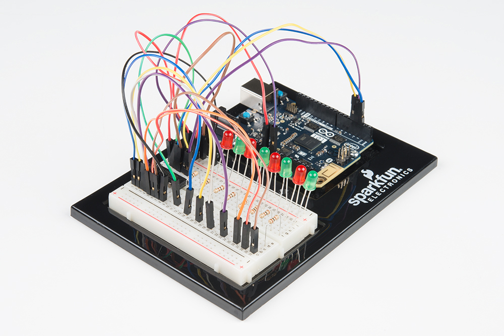
故障诊断
Arduino 的电源 LED 熄灭
这种情况在我们遇到过好几次了。当芯片插反时,会发生这种情况。如果您进行了快速修复,则不会有任何组件损坏。
未完全运行
很抱歉听上去像是老生常谈,不过可能就是如同跨接导线这样简单的错误而造成的。
遇到挫折
实验 17:使用 LCD
简介
在本实验中,您将学习如何使用 LCD。LCD(液晶显示器)是一种简单的屏幕,可以显示命令、少量信息或是来自传感器的读数 -- 所有这些都取决于如何对开发板进行编程。在此电路中,您将学习在项目中采用 LCD 的基础知识。
所需部件
您需要以下部件:
- 1x 实验电路板
- 1x Arduino 101 或 Genuino 101 开发板
- 1x 电位计
- 1x 3.3V LCD
- 16x 跳线
没有 SIK?
如果您要执行本实验,但又没有 SIK,那么我们建议您使用这些部件:
您还需要一个 Arduino 101 或 Genuino 101 开发板。
Arduino 101
DEV-13787
Genuino 101
DEV-13984LCD 屏幕简介

101 SIK 包含一个液晶显示器 (LCD) 屏幕。此屏幕类似于在微波仪器、汽车中的仪表板上或德州仪器语音训练机(年纪大的朋友可能记得)上可能找到的屏幕。LCD 屏幕是显示来自 101 开发板的数据或信息的好地方,而不必将它连接到笔记本电脑。
此 LCD 屏幕总共具有 32 个可能字符空间,它们按网格排列,包含两行,每行 16 个字符。LCD 通过一个库进行控制,从而可更加容易地将它与 101 开发板结合使用。接线似乎有点让人望而却步,不过这是值得尝试的挑战。
专业提示:对 LCD 屏幕进行接线时,从 LCD 针脚的一侧开始,朝着中央进行运行。遇到空缺的针脚之后,切换到另一侧,并重复过程。此方法可帮助防止意外缺失针脚或错误接线。
硬件接线
是否准备好开始对每个部件进行接线?请查看下面的接线图以了解如何连接每个部件。
| 极化组件 | 请特别注意组件用于指示如何在实验电路板上放置它的标记。极化组件只能按一个方向连接到电路。 |
实验的接线图
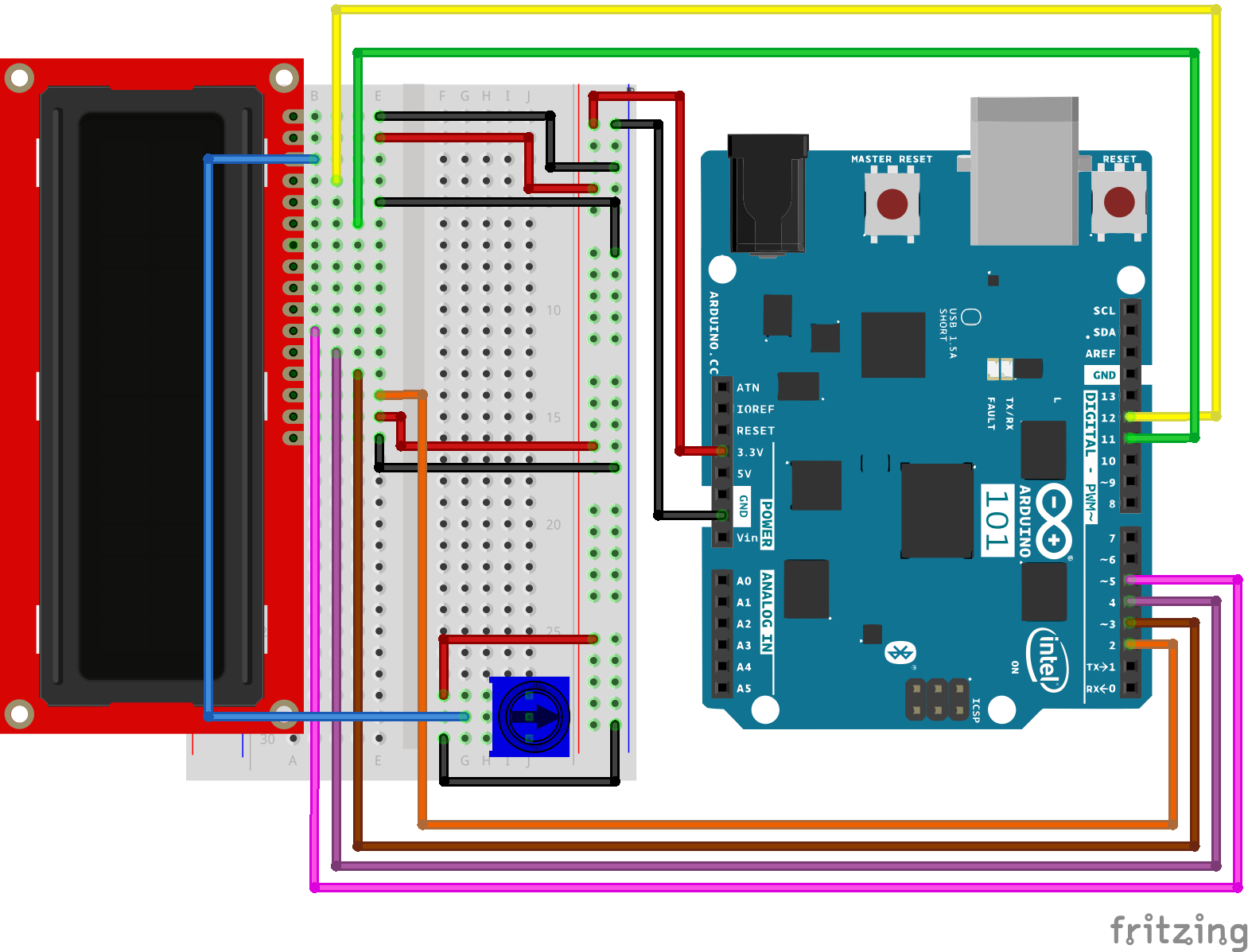
打开草图
在计算机上打开 Arduino IDE 软件。采用 Arduino 语言进行编码可控制电路。通过访问您先前下载并置于“示例”文件夹中的“101 SIK 指南代码”,来打开用于电路 17 的代码。
要打开该代码,请转到:文件 > 示例 > 101 SIK 指南代码 > Circuit_17
还可以将以下代码复制并粘贴到 Arduino IDE 中。点击“上传”,然后查看发生的情况!
language:cpp
/*
SparkFun Inventor's Kit
Example sketch 17

LIQUID CRYSTAL DISPLAY (LCD)

  This sketch will show you how to connect an LCD to your Arduino
  and display any data you wish.

This sketch was written by SparkFun Electronics,
with lots of help from the Arduino community.
This code is completely free for any use.
Visit https://www.sparkfun.com/products/12060 for SIK information.
Visit http://www.arduino.cc to learn more about Arduino.
*/

// Load the LiquidCrystal library, which will give us
// commands to interface to the LCD:

#include

// Initialize the library with the pins we're using.
// (Note that you can use different pins if needed.)
// See http://arduino.cc/en/Reference/LiquidCrystal
// for more information:

LiquidCrystal lcd(12,11,5,4,3,2);

void setup()
{
  // The LiquidCrystal library can be used with many different
  // LCD sizes. We're using one that's 2 lines of 16 characters,
  // so we'll inform the library of that:

  lcd.begin(16, 2);

  // Data sent to the display will stay there until it's
  // overwritten or power is removed. This can be a problem
  // when you upload a new sketch to the Arduino but old data
  // remains on the display. Let's clear the LCD using the
  // clear() command from the LiquidCrystal library:

  lcd.clear();

  // Now we'll display a message on the LCD!

  // Just as with the Arduino IDE, there's a cursor that
  // determines where the data you type will appear. By default,
  // this cursor is invisible, though you can make it visible
  // with other library commands if you wish.

  // When the display powers up, the invisible cursor starts
  // on the top row and first column.

  lcd.print("hello, world!");

  // Adjusting the contrast (IMPORTANT!)

  // When you run the sketch for the first time, there's a
  // very good chance you won't see anything on the LCD display.
  // This is because the contrast likely won't be set correctly.
  // Don't worry, it's easy to set, and once you set it you won't
  // need to change it again.

  // Run the sketch, then turn the potentiometer until you can
  // clearly see the "hello, world!" text. If you still can't
  // see anything, check all of your connections, and ensure that
  // the sketch was successfully uploaded to the Arduino.
}

void loop()
{
  // You can move the invisible cursor to any location on the
  // LCD before sending data. Counting starts from 0, so the top
  // line is line 0 and the bottom line is line 1\. Columns range
  // from 0 on the left side, to 15 on the right.

  // In additon to the "hello, world!" printed above, let's
  // display a running count of the seconds since the Arduino
  // was last reset. Note that the data you send to the display
  // will stay there unless you erase it by overwriting it or
  // sending an lcd.clear() command.

  // Here we'll set the invisible cursor to the first column
  // (column 0) of the second line (line 1):

  lcd.setCursor(0,1);

  // Now we'll print the number of seconds (millis() / 1000)
  // since the Arduino last reset:

  lcd.print(millis()/1000);

  // TIP: Since the numeric data we're sending is always growing
  // in length, new values will always overwrite the previous ones.
  // However, if you want to display varying or decreasing numbers
  // like a countdown, you'll find that the display will leave
  // "orphan" characters when the new value is shorter than the
  // old one.

  // To prevent this, you'll need to erase the old number before
  // writing the new one. You can do this by overwriting the
  // last number with spaces. If you erase the old number and
  // immediately write the new one, the momentary erase won't
  // be noticeable. Here's a typical sequence of code:

  // lcd.setCursor(0,1);   // Set the cursor to the position
  // lcd.print("       "); // Erase the largest possible number
  // lcd.setCursor(0,1);   // Reset the cursor to the original position
  // lcd.print(millis()/1000); // Print our value

  // NEXT STEPS:

  // Now you know the basics of hooking up an LCD to the Arduino,
  // and sending text and numeric data to the display!

  // The LCD library has many commands for turning the
  // cursor on and off, scrolling the screen, etc. See:
  // http://arduino.cc/en/Reference/LiquidCrystal
  // for more information.

  // Arduino also comes with a number of built-in examples
  // showing off the features of the LiquidCrystal library.
  // These are locted in the file/examples/LiquidCrystal menu.

  // Have fun, and let us know what you create!
  // Your friends at SparkFun.
}
要注意的代码
#include<liquidcrystal.h></liquidcrystal.h>
这段代码指示 Arduino IDE 包含用于简单 LCD 显示器的库。如果没有它,则任何命令都无法起作用,因此请确保包含它!
lcd.print(“hello, world!”);
这是您首次在屏幕上显示内容。您可能需要调整对比度以使其可见。转动电位计,直到您可以清晰地看到文本。
lcd.clear();
是的,您猜对了。此方法用于清除打印到 LCD 上的任何数据。
lcd.setCursor(0,1);
如果您靠近观察,便会注意到,每个字符周围都有一个小框,这些框位于 2x16 网格中。此方法中的第一个数字是列(从零开始计数...必须习惯这一点!),第二个数字是行。因此,此值为 0,1 表示第一列、第二行。
应看到的情况
最初,您应看到“hello, world!”这些词在 LCD 上弹出。请记住,如果无法清晰地辨认这些词,可以使用电位计调整对比度。如果您遇到任何问题,请确保代码正确并仔细检查连接。另请查看下面的“故障诊断”部分。
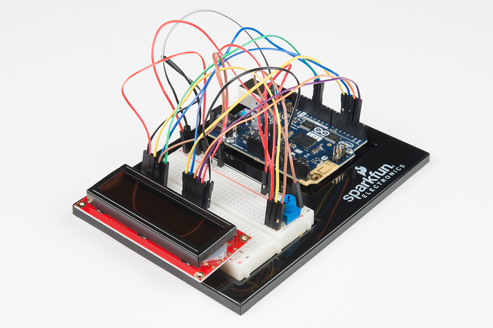
故障诊断
屏幕空白或完全亮起
通过旋转电位计来调整对比度。如果未进行正确调整,则您无法阅读文本。
完全不运行
仔细检查代码,特别是您是否包含了 LCD 库。
屏幕闪烁
仔细检查实验电路板和 101 开发板的连接。
实验 18:读取板载加速度计
简介
在实验 13 中,您尝试使用不同输入来控制马达的速度和方向。在本实验中,您将进行类似的操作,不过是使用 Arduino 101 开发板上的板载重力感应器作为输入。
重力感应器测量在不同方向上应用于传感器的重力。如果重力感应器在四处移动,则您可以从重力感应器数据推断出许多信息。不过在它静止时,也可以方便地确定向下的方向。地球的重力是始终存在的力,可以由重力感应器进行测量。我们将这样使用它确定 Arduino 101 开发板的方向,在其中让马达向前驱动、向后驱动或不执行任何操作。让我们开始吧!
所需部件
您需要以下部件:
- 1x 实验电路板
- 1x Arduino 101 或 Genuino 101 开发板
- 1x SparkFun 马达驱动器
- 1x 42:1 业余级齿轮马达
- 13x 跳线
没有 SIK?
如果您要执行本实验,但又没有 SIK,那么我们建议您使用这些部件:
您还需要一个 Arduino 101 或 Genuino 101 开发板。
Arduino 101
DEV-13787
Genuino 101
DEV-13984推荐阅读
继续进行本实验之前,我们建议您熟悉以下教程中的概念:
重力感应器简介
重力感应器是测量加速度的设备,而加速度是物体速度的变化速率。其测量单位是米/平方秒 (m/s2) 或 G 力 (g)。在地球行星上,一个 G 力等于 9.8 m/s2,但是这会因海拔而稍有不同(并且在不同行星上,会由于万有引力的变化而是不同值)。重力感应器可用于感应系统中的振动或方向应用。
硬件接线
是否准备好开始对每个部件进行接线?请查看下面的接线图以了解如何连接每个部件。
| 极化组件 | 请特别注意组件用于指示如何在实验电路板上放置它的标记。极化组件只能按一个方向连接到电路。 |
实验的接线图
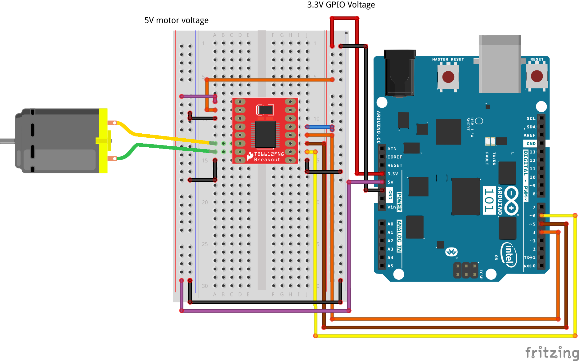
打开草图
在计算机上打开 Arduino IDE 软件。采用 Arduino 语言进行编码可控制电路。通过访问您先前下载并置于“示例”文件夹中的“101 SIK 指南代码”,来打开用于电路 18 的代码。
要打开该代码,请转到:文件 > 示例 > 101 SIK 指南代码 > Circuit_18
还可以将以下代码复制并粘贴到 Arduino IDE 中。点击“上传”,然后查看发生的情况!
language:cpp
/*
SparkFun Inventor's Kit
Example sketch 18

Controlling a Motor Using an Accelerometer

  Use the on-board accelerometer of the 101 board as an input to control
  a motor based on its orientation in space. If you tilt the 101 to the left,
  the motor spins in one direction; tilted to the right, it spins the opposite direction; and if it
  is flat, the motor stops.

This sketch was written by SparkFun Electronics, and based on the Orientation example
in the CurieIMU Library Examples
This code is completely free for any use.
Visit http://learn.sparkfun.com/products/2 for SIK information.
Visit http://www.arduino.cc to learn more about Arduino.
*/

#include "CurieIMU.h"

const int DIR_A = 4;
const int DIR_B = 5;
const int PWM = 6;

// previous orientation (for comparison). Start at (-1) to start with

void setup()
{
 //set motor control pins to OUTPUT
pinMode(DIR_A, OUTPUT);
pinMode(DIR_B, OUTPUT);
pinMode(PWM, OUTPUT);

 // Start the acceleromter
 CurieIMU.begin();

// Set the accelerometer range to 2G
CurieIMU.setAccelerometerRange(2);
}

void loop()
{
 // read accelerometer:
 int x = CurieIMU.readAccelerometer(X_AXIS);
 int y = CurieIMU.readAccelerometer(Y_AXIS);
 int z = CurieIMU.readAccelerometer(Z_AXIS);

 // calculate the absolute values, to determine the largest
 int absX = abs(x);
 int absY = abs(y);
 int absZ = abs(z);

if ( (absZ > absX) && (absZ > absY))
{
 // base orientation on Z
 if (z > 0)
 {
  brake();
 }
}

 //else if Y is greater than X and Z its on edge
 else if ( (absY > absX) && (absY > absZ))
 {
  // if Y is positive orientation (digital pins up)and is set to 1
  if (y > 0)
  {
    forward();
  }
  //the Y is in the negative orientation (analog pins up) and is set to 2
  else
  {
    reverse();
  }
}
}
//custom function for driving the motor forward
void forward()
{
  digitalWrite(DIR_A, HIGH);
  digitalWrite(DIR_B, LOW);
  digitalWrite(PWM, HIGH);
}

//custom function for driving the motor in reverse
void reverse()
{
  digitalWrite(DIR_A, LOW);
  digitalWrite(DIR_B, HIGH);
  digitalWrite(PWM, HIGH);
}

//custom function for braking the motor
void brake()
{
  digitalWrite(DIR_A, LOW);
  digitalWrite(DIR_B, LOW);
  digitalWrite(PWM, LOW);
}
要注意的代码
#include "CurieIMU.h"
Arduino 的串行端口可以用于接收以及发送数据。因为数据可能随时到达,所以 Arduino 101 开发板会存储(或“缓冲”)进入端口的数据,直到您准备好使用数据。Serial.available() 命令会返回端口已收到,但是尚未由草图使用的字符数。零表示没有数据到达。
int x = CurieIMU.readAccelerometer(X_AXIS);
我们通过将常量 X_AXIS 传递给 CurieIMU 的 readAccelerometer 方法来读取重力感应器值。这会从传感器返回实时读数。要读取其他轴,可以向该方法传递常数 X_AXIS、Y_AXIS 和 Z_AXIS。
int absX = abs(x);
在本实验中,我们不必关心是正值还是负值。我们只需知道哪个值是最大值,我们可以从中进行决策。我们使用了“abs()”函数,它采用数字的绝对值(基本上是去掉 (-) 符号)。我们将该值存储在一个名为“absX”的本地变量中,以便如果我们要访问原始 x 值,则仍可以执行该操作。
language:cpp
//if Z axis is greater than X and Y its facing upright
if ( (absZ > absX) && (absZ > absY))
{
 // base orientation on Z
 if (z > 0)
 {
  brake();
 }
}

 //else if Y is greater than X and Z its on edge
 else if ( (absY > absX) && (absY > absZ))
 {
  // if Y is positive orientation (digital pins up)and is set to 1
  if (y > 0)
  {
    forward();
  }
  //the Y is in the negative orientation (analog pins up) and is set to 2
  else
  {
    reverse();
  }
}
使重力感应器读数成为绝对值之后,我们可以使用 if() 语句比较它们。在本实验中,我们只希望比较与向左和向右倾斜开发板有关的值,不过仍会采用三个轴来进行确定。例如,如果 Y 大于 X,则 Y 轴指向下方(指向重力方向)。我们随后进行最终比较,了解它是否大于 0 以确保它处于正方向。我们基于这些比较设置马达的方向。
应看到的情况
代码上传到 101 开发板之后,拿起 101 开发板并向左倾斜它(模拟输入针脚向下)。马达应开始按一个方向运行。现在朝相反方向倾斜它(数字 GPIO 针脚向下),马达应按相反方向运行。将开发板平放时,马达应停止。如果不是这样,请查看下面的“故障诊断”部分。
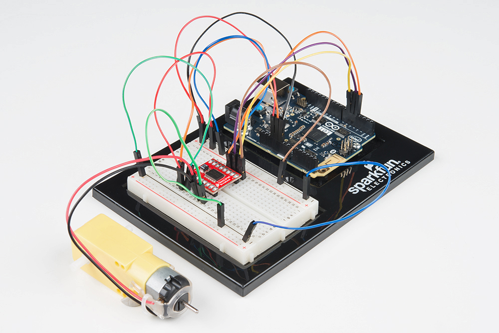
故障诊断
马达未旋转
确保对马达控制器接线正确。因为这里有许多导线!
仍未成功
仔细检查代码是否上传到 101 开发板。有时将数据上传到 101 开发板需要一段时间,因此请耐心等候!
仍未运行
Arduino 有时会与计算机断开连接。尝试拔下它,然后重新插入 USB 端口。
实验 19:点击检测
简介
101 开发板的一个优势在于,它在姿势和移动识别方面具有十分先进的技术。这一切都通过 101 开发板上的惯性测量单元 (IMU) 来实现。IMU 可测量重力感应器(重力)和陀螺仪(旋转)数据。我们在实验 18 中已尝试了重力感应器。让我们更深入一些并利用 Curie 模块(该模块可以理解数据的含义,以确定您是否在迈步并进行计数),从而检测您是否在开发板上点击甚至其空间方向。
作为将 IMU 与 Curie 模块结合使用的示例,我们将创建一个简单 RGB 电路,当您在 101 开发板顶部双击时,它会呈绿色闪烁两次,当您在 101 开发板底部双击时,它会呈红色闪烁两次。
所需部件
您需要以下部件:
- 1x 实验电路板
- 1x Arduino 101 或 Genuino 101 开发板
- 1x 共阴极 RGB LED
- 3x 100Ω 电阻
- 6x 跳线
没有 SIK?
如果您要执行本实验,但又没有 SIK,那么我们建议您使用这些部件:
您还需要一个 Arduino 101 或 Genuino 101 开发板。
Arduino 101
DEV-13787
Genuino 101
DEV-13984推荐阅读
继续进行本实验之前,我们建议您熟悉以下教程中的概念:
惯性测量单元简介
惯性测量单元 (IMU) 是一种传感器组合,用于确定传感器在三维空间中的方向。101 开发板使用重力感应器和陀螺仪检测物理方向(通过测量对传感器施加的重力),并使用陀螺仪检测旋转运动。
101 开发板可以将 IMU 数据转换为某些预编程的姿势,如:迈步、点击或双击它或是使开发板落下。本实验重点检测点击/双击,但是请尝试位于文件 > 示例 > CurieIMU下的其他示例代码。
注:101 开发板具有一个组装在开发板上的 IMU,可通过 Arduino 库进行访问。使用该 IMU 无需接线!
硬件接线
是否准备好开始对每个部件进行接线?请查看下面的接线图以了解如何连接每个部件。
| 极化组件 | 请特别注意组件用于指示如何在实验电路板上放置它的标记。极化组件只能按一个方向连接到电路。 |
实验的接线图
打开草图
在计算机上打开 Arduino IDE 软件。采用 Arduino 语言进行编码可控制电路。通过访问您先前下载并置于“示例”文件夹中的“101 SIK 指南代码”,来打开用于电路 19 的代码。
要打开该代码,请转到:文件 > 示例 > SIK 指南代码 > Circuit_19
还可以将以下代码复制并粘贴到 Arduino IDE 中。点击“上传”,然后查看发生的情况!
language:cpp
/*
SparkFun Inventor's Kit
Example sketch 19

TAP DETECTION

Use the 101 board's on-board IMU to detect a tap and double tap and react accordingly.

This sketch was written by SparkFun Electronics,
with lots of help from the Arduino community.
This code is completely free for any use.
Visit http://learn.sparkfun.com/products/2 for SIK information.
Visit http://www.arduino.cc to learn more about Arduino.
*/

#include "CurieIMU.h"

void setup()
{

 pinMode(5, OUTPUT);
 pinMode(6, OUTPUT);

 // Initialise the IMU
 CurieIMU.begin();
 CurieIMU.attachInterrupt(eventCallback);

 // Increase Accelerometer range to allow detection of stronger taps (< 4g)
 CurieIMU.setAccelerometerRange(3);

 // Reduce threshold to allow detection of weaker taps (>= 750mg)
 CurieIMU.setDetectionThreshold(CURIE_IMU_TAP, 750); // (750mg)

 // Set the time window for 2 taps as a double tap (<= 250 milliseconds)
 CurieIMU.setDetectionDuration(CURIE_IMU_DOUBLE_TAP, 250);

 // Enable Double-Tap detection
 CurieIMU.interrupts(CURIE_IMU_DOUBLE_TAP);
 }

void loop()
{
 // nothing happens in the loop because all the action happens
 // in the callback function.
 }

static void eventCallback()
{
 if (CurieIMU.getInterruptStatus(CURIE_IMU_DOUBLE_TAP)) {
    if (CurieIMU.tapDetected(Z_AXIS, NEGATIVE))
    {
    digitalWrite(5, HIGH);
    digitalWrite(6, LOW);
    delay(250);
    digitalWrite(5, LOW);
    digitalWrite(6, LOW);
    delay(250);
    digitalWrite(5, HIGH);
    digitalWrite(6, LOW);
    delay(250);
    digitalWrite(5, LOW);
    digitalWrite(6, LOW);
    delay(250);
    }
   else if (CurieIMU.tapDetected(Z_AXIS, POSITIVE))
   {
    digitalWrite(5, LOW);
    digitalWrite(6, HIGH);
    delay(250);
    digitalWrite(5, LOW);
    digitalWrite(6, LOW);
    delay(250);
    digitalWrite(5, LOW);
    digitalWrite(6, HIGH);
    delay(250);
    digitalWrite(5, LOW);
    digitalWrite(6, LOW);
    delay(250);
   }
  else
  {
  digitalWrite(5, LOW);
  digitalWrite(6, LOW);
  }
 }
}
要注意的代码
CurieIMU.begin();
初始化或开始使用板载 IMU。如果没有此 IMU,则 101 开发板从不会寄存任何 IMU 数据。
CurieIMU.attachInterrupt(eventCallback);
中断是中断循环并指示 101 开发板立即执行某种操作的事件。101 开发板随后会跳出循环,执行该操作,然后返回到循环中。中断会指定在触发中断时要执行的函数。在此示例中是 eventCallback。
 // Reduce threshold to allow detection of weaker taps (>= 750mg)
 CurieIMU.setDetectionThreshold(CURIE_IMU_TAP, 750); // (750mg)

 // Set the time window for 2 taps as a double tap (<= 250 milliseconds)
 CurieIMU.setDetectionDuration(CURIE_IMU_DOUBLE_TAP, 250);
要使用 IMU 检测双击,需要进行一些设置。需要为硬点击以及软点击设置力阈值。还需要为双击指定持续时间,以便 Curie 可以判断单击与双击之间的差异。
CurieIMU.interrupts(CURIE_IMU_DOUBLE_TAP); 最后,我们将中断附加到双击事件。因此只要双击事件发生,101 开发板便会执行 eventCallback 函数。
应看到的情况
代码上传之后,RGB 应熄灭。拿起开发板并使用手指以类似于鼠标双击的节奏和时间在开发板顶部双击。RGB 应呈绿色闪烁两次,然后再次熄灭。如果您在开发板底部执行相同操作,则它会呈红色闪烁。
故障诊断
库未进行编译
仔细检查是否使用了 #include "CurieIMU.h" 语句。如果使用了,请确保头文件名处于引号中,而不是书名号中。
未捕获双击
101 开发板在特定时间范围内查找双击。请尝试加快双击速度,或是在 CurieIMU.setDetectionDuration(CURIE_IMU_DOUBLE_TAP, 250); 方法中调整双击时间。
仍未运行
可以设置重力感应器的灵敏度。例如设置为 2G,或是我们在地球上通常体验的重力量的两倍。如果减小该值,则会提高灵敏度。
实验 20:使用板载实时时钟 (RTC)
简介
微控制器十分擅长依据自己的计时方式“守时”。我们的意思是指其运行时间;它们按照内部时钟信号来运行,该信号使您可以跟踪自加电以来的毫秒数和微秒数。但是微控制器没有任何方法来了解实际时间,而实际时间是我们所有人用作日常工作和计划的基础的时间。
在本实验中,您将设置时钟,然后在 LCD 屏幕(您已在实验 17 中学习了如何使用它)上显示日期和时间。
注:101 开发板没有用于 RTC(实时时钟)的备用电池,因此如果您拔下开发板或电池耗尽,则必须在代码中重置 RTC 或开发使您可以调整时间的电路。
所需部件
您需要以下部件:
- 1x 实验电路板
- 1x Arduino 101 或 Genuino 101 开发板
- 1x 电位计
- 1x 3.3V LCD
- 16x 跳线
没有 SIK?
如果您要执行本实验,但又没有 SIK,那么我们建议您使用这些部件:
您还需要一个 Arduino 101 或 Genuino 101 开发板。
Arduino 101
DEV-13787
Genuino 101
DEV-13984推荐阅读
继续进行本实验之前,我们建议您熟悉以下教程中的概念:
实时时钟 (RTC) 简介
微控制器在保持运行时间(执行其作业所需的时序)方面表现优异。微控制器通过可跟踪自加电以来的毫秒数。但是,它们不擅长跟踪我们人类所使用的时间(“实际时间”)。微控制器使用实时时钟 (RTC) 来跟踪设置的起始点和不断前进的时间。
RTC 可跟踪时钟的小时、分钟和秒以及日历的天、月和年。在 101 开发板上,这要求您在首次加电时设置时间和日期。从该时间点起,它应该保持准确的时间。您随后可以使用时间触发事件在特定时间或日期发生,甚至可将它用作时间戳来记录数据。
注:如果 101 开发板断电,则您需要在代码中重置时钟。此外,RTC 是 101 开发板的板载组件,无需进行进一步接线。
硬件接线
是否准备好开始对每个部件进行接线?请查看下面的接线图以了解如何连接每个部件。
| 极化组件 | 请特别注意组件用于指示如何在实验电路板上放置它的标记。极化组件只能按一个方向连接到电路。 |
实验的接线图
打开草图
在计算机上打开 Arduino IDE 软件。采用 Arduino 语言进行编码可控制电路。通过访问您先前下载并置于“示例”文件夹中的“101 SIK 指南代码”,来打开用于电路 20 的代码。
要打开该代码,请转到:文件 > 示例 > 101 SIK 指南代码 > Circuit_20
还可以将以下代码复制并粘贴到 Arduino IDE 中。点击“上传”,然后查看发生的情况!
language:cpp
/*
SparkFun Inventor's Kit
Example sketch 20

DISPLAYING THE DATE AND TIME

This sketch reads the RTC data and prints it on the LCD screen

This sketch was written by SparkFun Electronics,
with lots of help from the Arduino community.
This code is completely free for any use.
Visit http://learn.sparkfun.com/products/2 for SIK information.
Visit http://www.arduino.cc to learn more about Arduino.
*/

//include the CurieTime Library
#include
#include

//instantiate the lcd
LiquidCrystal lcd(12, 11, 5, 4, 3, 2);

void setup()
{
  //start lcd at 16 x 2
  lcd.begin(16, 2);

  //clear the lcd
  lcd.clear();

  //set time to 1:35:24 on April 4th, 2016\. Please change to your time / date
  setTime(1, 35, 24, 4, 10, 2016);
}

void loop()
{
 //create a character array of 16 characters for the time
 char clockTime[16];
 //use sprintf to create a time string of the hour, minte and seconds
 sprintf(clockTime, "    %2d:%2d:%2d    ", hour(), minute(), second());

 //create a character array of 15 characters for the date
 char dateTime[16];
 //use sprintf to create a date string from month, day and year
 sprintf(dateTime, "   %2d/%2d/%4d   ", month(), day(), year());

 //set cursor to column 0, row 0
 lcd.setCursor(0, 0);
 //print the date string over lcd
 lcd.print(dateTime);
 //set cursor to column 0, row 1
 lcd.setCursor(0, 1);
 //print the time string over lcd
 lcd.print(clockTime);
}
要注意的代码
setTime(1,35,00,4,10,2016);
101 开发板上的 RTC 在加电时必须进行设置。可使用 setTime() 函数执行此操作。需要按小时、分、秒、月、天、年的顺序向 setTime() 传递 6 个参数。如果 101 开发板由于某种原因而断电,则您必须使用此函数重置它。
sprintf(dateTime, " %2d/%2d/%4d ", month(), day(), year()); sprintf() 是字符串构建函数。这是通过接收数据并将它们置于字符数组(这在 Arduino 中基本上就是字符串)中来构建字符串的简单方式。%2d 和 %4d 中有趣的一点在于数据在插入时指定了数字位数,因此 %4d 是 4 位数。最后将要插入到字符串中的数据作为参数进行传递。在此例中是 month()、day() 和 year()。
应看到的情况
代码完全上传之后,您应看到 LCD 屏幕上显示两行文本。第一行应是日期(只应每天更改一次),第二行应是当前时间(应看到它在持续计数)。如果不是这样,请查看下面的“故障诊断”部分。
故障诊断
屏幕空白或完全亮起
通过旋转电位计来调整对比度。如果未进行正确调整,则您无法阅读文本。
完全不运行
仔细检查代码,特别是您是否包含了 LCD 库。
未显示正确时间
仔细检查代码。您可能必须更新 setTime() 函数。
实验 21:使用板载低功耗蓝牙 (BLE)
简介
我们现在要进行最后一个实验,兜了一圈后又回到了单个 LED。不过这次实验有一些复杂!这次并是使这一单独的 LED 闪烁,而是将通过手机或平板电脑控制它!
101 开发板内置了低能量蓝牙 (BLE)。对于您而言,这意味着您可以开始从手机控制 101 开发板。BLE 使用基于服务/属性的设备通信方法。从长远来看,此方法可使跨多个设备进行的开发更加容易,但是如果您刚刚接触它,则可能会觉得有些困难。本实验涵盖将有助于进行通信的应用程序加载到设备中,我们将查看使用 BLE 的示例草图。
这是您最后一个实验,但是绝不是您学习 101 开发板的终点。我们强烈建议查看 Arduino 网站以了解有关 101 开发板的详细信息以及支持材料将如何发展和改进。
所需部件
您需要以下部件:
- 1x 实验电路板
- 1x Arduino 101 或 Genuino 101 开发板
- 1x LED
- 1x 100Ω 电阻
- 3x 跳线
没有 SIK?
如果您要执行本实验,但又没有 SIK,那么我们建议您使用这些部件:
您还需要一个 Arduino 101 或 Genuino 101 开发板。
Arduino 101
DEV-13787
Genuino 101
DEV-13984推荐阅读
继续进行本实验之前,我们建议您熟悉以下教程中的概念:
低能量蓝牙 (BLE) 简介
低能量蓝牙 (BLE) 是使用蓝牙的相对较新通信协议。BLE 正越来越多地用于可穿戴和物联网 (IoT) 应用,在这些应用中,电源管理是一个值得关注的问题,并且您的设备需要能够与众多设备(如手机、汽车和其他 BLE 设备)进行通信。
为了标准化与各种各样的设备之间的通信协议,BLE 使用基于常规属性 (GATT) 的系统,该系统使用基于设备功能的服务组成的层次结构。例如,Fitbit 可能具有心率服务以及计步器服务。每个服务都可以分配属性。这些属性将承载服务的原始数据。
一个示例属性是针对有关与之通信的设备的信息以及对给定服务十分重要的数据进行通信。在 Fitbit 示例中,步数或脉搏数就可以是一个属性。大体的思路如下:有一些服务能使设备了解期望从彼此获得的信息,并让彼此保持统一,以便来回共享属性。GATT 能采用其最简单的形式让设备对彼此进行假设并开始处理重要内容...共享您尝试传达的信息。
注:BLE 内置在 101 开发板上的 Curie 模块中,除了连接您要通过 BLE 进行控制的对象,无需进行任何接线。
硬件接线
是否准备好开始对每个部件进行接线?请查看下面的接线图以了解如何连接每个部件。
| 极化组件 | 请特别注意组件用于指示如何在实验电路板上放置它的标记。极化组件只能按一个方向连接到电路。 |
实验的接线图
安装 BLE 应用程序
为了准备充分,并通过将 BLE 与 Arduino 101 结合使用来运行,我们建议使用 nRF Master Control Panel 应用程序。该应用程序可以用于 Android 和 iOS 设备,最棒的地方在于它是免费的!
要下载该应用程序,请转到 Google Play Store 或 Apple App Store 并搜索 nRF。在准备好并运行 BLE 之后,我们强烈建议您尝试 nRF 提供的一些其他工具,但是现在,我们只需要 Master Control Panel。搜索、下载并安装应用程序 -- 随后您便已准备就绪!
打开草图
在计算机上打开 Arduino IDE 软件。采用 Arduino 语言进行编码可控制电路。通过访问您先前下载并置于“示例”文件夹中的“101 SIK 指南代码”,来打开用于电路 21 的代码。
要打开该代码,请转到:文件 > 示例 > 101 SIK 指南代码 > Circuit_21
还可以将以下代码复制并粘贴到 Arduino IDE 中。点击“上传”,然后查看发生的情况!
language:cpp
/*
SparkFun Inventor's Kit
Example sketch 21

BASIC BLE CONTROL

Turn an LED on and off using BLE and either a phone or tablet. Android and iOS devices only!

Based off of the BLE LED example written by Intel Corporation and included with the Curie BLE Arduino Library.

*/

 #include

BLEPeripheral blePeripheral;  // BLE Peripheral Device (the board you're programming)
BLEService ledService("19B10000-E8F2-537E-4F6C-D104768A1214"); // BLE LED Service

//set BLE characteristic
switchCharacteristic("19B10001-E8F2-537E-4F6C-D104768A1214", BLERead | BLEWrite);

const int ledPin = 13; // pin to use for the LED

 void setup()
{
 // set LED pin to output mode
  pinMode(ledPin, OUTPUT);

  // set advertised local name and service UUID:
  blePeripheral.setLocalName("101 Board");
  blePeripheral.setAdvertisedServiceUuid(ledService.uuid());

  // add service and characteristic:
   blePeripheral.addAttribute(ledService);
   blePeripheral.addAttribute(switchCharacteristic);

   // set the initial value for the characeristic:
   BLEUnsignedCharCharacteristic switchCharacteristic.setValue(0);

   // begin advertising BLE service:
   blePeripheral.begin();
 }

void loop()
{
  // listen for BLE peripherals to connect:
 BLECentral central = blePeripheral.central();

 // if a central is connected to peripheral:
  if (central)
  {
   // while the central is still connected to peripheral:
    while (central.connected())
    {
      // if the remote device wrote to the characteristic,
      // use the value to control the LED:
      if (switchCharacteristic.written())
      {
          // any value other than 0, turn on the LED
         if (switchCharacteristic.value())
         {
         digitalWrite(ledPin, HIGH);
         }
      //else turn the LED off
       else
      {
      digitalWrite(ledPin, LOW);
      }
      }
     }
    }
  }
要注意的代码
BLEService ledService("19B10000-E8F2-537E-4F6C-D104768A1214");
BLE 基于服务,使用名为全局唯一标识符 (UUID) 的自定义字符串预定义了一些服务。此字符串的长度是 16 字节,顾名思义,它在全局是唯一的。这是使用特定 UUID 实例化 BLEService 对象 ledService。
switchCharacteristic("19B10001-E8F2-537E-4F6C-D104768A1214", BLERead | BLEWrite);
特征和属性在服务下绑定在一起。您可以创建特征及其自己的 UUID,并将它们设置为可读、可写或是可读写。我们选择设置为可读写。请注意,特征 UUID 是一个与服务 UUID 不同的数字。
blePeripheral.setLocalName("101 Board");
您可以使用 setLocalName() 方法来命名 101 开发板。使用引号向它传递字符串。我们建议将此名称设为可以方便地识别为您自己的开发板,尤其是如果您在课堂上使用 101 开发板。
   blePeripheral.setAdvertisedServiceUuid(ledService.uuid());

   // add service and characteristic:
   blePeripheral.addAttribute(ledService);
   blePeripheral.addAttribute(switchCharacteristic);

   // set the initial value for the characeristic:
   switchCharacteristic.setValue(0);

   // begin advertising BLE service:
   blePeripheral.begin();
在这段代码中,我们向外围设备添加一个服务,然后将属性绑定或添加到外围设备。我们添加 ledService,并通过 switchCharacteristics 控制它。我们最后将 switchCharacteristics 的起始值设置为 0,然后启动外围设备。
在其中的循环函数中,我们确保外围设备与中央设备(手机)之间存在连接。具有连接时,我们检查是否存在特征以及它是否已写入。如果存在 0 以外的值,则我们打开 LED;如果没有值,或是值为 0,则关闭 LED。
应看到的情况
在设备上打开蓝牙连接并启动 Master Control Panel 应用程序。扫描设备,选择您的 101 开发板,然后连接到它。

连接之后,打开未知服务,然后选择 switchvalue。单击上传徽标(向上箭头)。这会显示一个对话框。输入 0 以外的数字,然后单击“发送”。
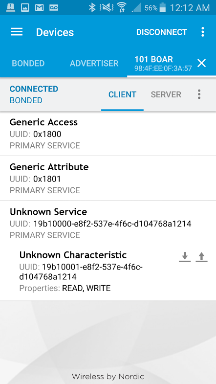
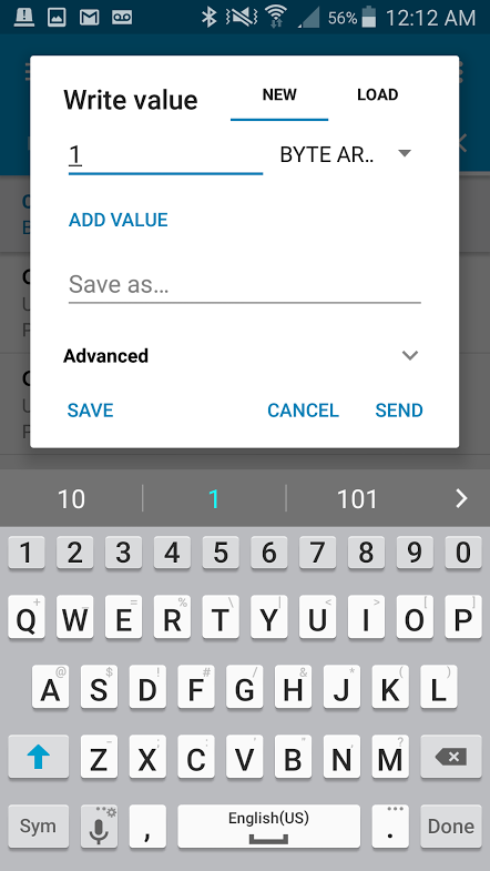
LED 应打开!显示相同的对话框,输入数字 0,然后单击“发送”。LED 应关闭。

故障诊断
LED 未亮起
您知道常规程序:检查接线,检查 LED 是否反向插入。
无法连接到 101 开发板的蓝牙
确保草图已上传!必须上传草图才能从 101 开发板广播 BLE 信号。
仍未运行
尝试重新启动手机或平板电脑的蓝牙并再次扫描本地设备。
Resources and Going Further
您可以将多种传感器和防护板接到 Arduino 101 开发板,以推动项目更上一层楼。下面是一些额外的阅读内容,可能会帮助您了解有关电子世界的更多信息。
如需有关 Arduino 的详细信息,请查看以下这些教程:
如需更多硬件相关教程,请阅读以下这些内容: