Sound Detector Hookup Guide
 Byron J.
 Introduction
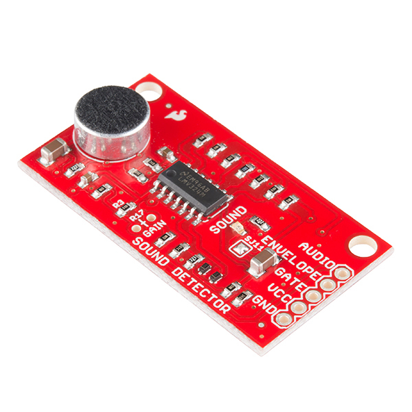
The Sound Detector is a small board that combines a microphone and some processing circuitry. It provides not only an audio output, but also a binary indication of the presence of sound, and an analog representation of it's amplitude.
Covered in This Tutorial
This tutorial will guide you through hooking up and using the Sound Detector. It will examine how the circuit works, explain some details about getting the best performance from the Sound Detector, then present two different projects that demonstrate how to use it.
Suggested Reading
- How to Use a Breadboard
- Analog vs. Digital
- The Wikipedia article on sound.
Quick Start
To get started with the Sound Detector, simply connect it to a power supply.
(Sound Detector → Power Supply )
- GND → Supply Ground.
- VCC → Power supply voltage between 3.5 and 5.5 Volts. 5 Volts is ideal.
In a quiet room, power the board up, and then speak into the microphone. You should see the red LED on the board blink in response to your voice.
With its 3 outputs, the board itself is a lot more flexible. To explore that flexibility, read on.
Looking Closer
Three Outputs?
The Sound Detector has 3 separate outputs. It's easiest to see what each is doing with a graph. The following illustrates how the sound detector responds to a series of sound pulses.
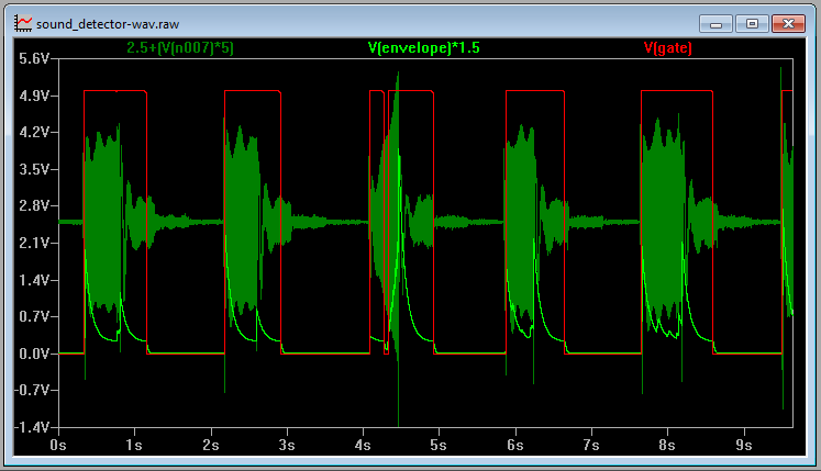
This shows the output voltages over time.
- The dark green trace is the audio output of the sound detector. The audio voltage directly from the microphone is found at this output.
- The light green trace is the envelope output. This analog voltage traces the amplitude of the sound. Of particular interest, notice that the third pulse gets noticeably louder as it goes.
- Finally, the red line is the gate output. This output is low when conditions are quiet and goes high when sound is detected.
How It Works
Having examined the outputs, lets also take a quick walk through the schematic, to gain an understanding of how each stage works.
First Stage
The first section of the circuit is an electret microphone capsule. This portion of the circuit borrows from the Electret Microphone breakout board.
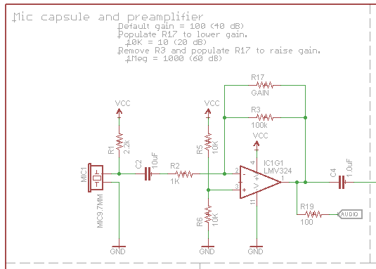
The capsule is biased by the supply voltage through R1, and it outputs an AC voltage that is riding a DC offset of approximately 1/2 the supply voltage.
The output from the capsule is an extremely small voltage, so the signal from the capsule is amplified by IC1G1, an operational amplifier stage. By default, the preamplifier has an arithmetic gain of 100 (20 dB), and the gain can be adjusted by populating R17 (which we'll examine in detail on the next page).
The audio output is DC coupled, riding one half the supply voltage, so it can be directly connected to the ADC of a microcontroller. In perfectly quiet conditions, it will ideally read 1/2 full scale, or 512 on a 10-bit converter.
Second Stage
The second stage of the circuit is an envelope follower.
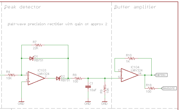
IC1G3 forms an opamp-based precision rectifier. This stage implements the equation
if(Vin > 0)
    Vout = 0;
else
    Vout = Vin * -2.2
The opamp inverts and amplifies the signal. When it's output swings high, D2 turns on, and charges C1. When the opamp output is high or not swinging, D2 is turned off, and C1 discharges through R9. Thus, C1 tracks the peaks of the input signal.
IC1G4 is a buffer amplifier, so external loads on the envelope pin won't change the C1's charge/discharge behavior.
This results in a signal that tracks the peak amplitude of the input signal. A louder sound will result in a higher voltage on the Envelope pin. As with the audio pin, the envelope can be connected to the ADC of a microcontroller.
Third Stage
The final stage implements a thresholded switch on the envelope signal.
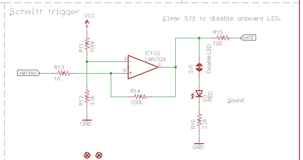
The Schmitt trigger watches the envelope signal, and toggles the output when the threshold is exceeded. A Schmitt trigger is a comparator that adjusts it's threshold voltage when the output switches, requiring a higher voltage to switch on than to switch off. This allows it to ignore some ripple in the input signal, like the ripple present in the output of the envelope follower stage.
The output of the Schmitt trigger is found on the Gate pin. You can connect it to a digital input. We'll use it to trigger interrupts in the software example.
Outputs
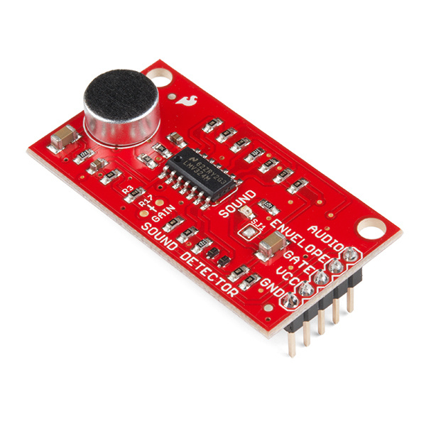
Each of the three output signals is present on the .1" header at the edge of the board. They are active simultaneously. If you aren't using one in your particular application, simply leave that pin disconnected.
Configuration
Care and Feeding Of The Capsule
The heart of the Sound Detector is the electret microphone capsule -- without it, we couldn't convert acoustic energy into electrical energy. These capsules have a couple of quirks that we need to understand in order to apply them successfully.
Inside the capsule is the diaphragm, which is actually one plate of a small capacitor. That capacitor forms a voltage divider with the external bias resistor. The diaphragm moves in response to sound, and the capacitance changes as the plates get closer together or farther apart, causing the divider to change. Since capacitors are sensitive to loading, it's internally buffered with a JFET (junction field-effect transistor).
Due to the mechanical and electronic tolerances involved, some capsules are more sensitive than others. Also, the JFET is rather sensitive to noise on the power supply. Both of these factors need to be accounted for when deploying the Sound Detector.
Power Supply
The Sound Detector is an analog circuit, and as such, it's more sensitive to noise on the power supply than most digital circuits. Since the capsule is effectively a voltage divider sitting across the power rails, it will transcribe any noise on the supply lines onto the capsule output. The next circuit in the chain is a high-gain amplifier, so any noise on the supply will then be amplified. Therefore, the Sound Detector may require more careful power supply configuration than many circuits.
In testing with various supplies, a significant degree of variability was discovered - some supplies are less noisy than others. One exhibited as much as 30 mV ripple on the supply output, an as a result, the the Sound Detector was rather sensitive and unstable. You can check how clean a power supply is by checking it with an oscilloscope or volt meter, set to the AC Volts (or, if provided, the AC millivolts) range. A truly clean supply will show 0.000 VAC. Based on the supplies used in testing, ripple of more than about 10 mV is problematic.
Powering my Arduino with a 9V external supply, which allows the onboard regulators to function, the Arduino's 5V output was sufficiently clean. However, powering it from the 5V available on the USB port on a PC, the regulators are bypassed, and the results were somewhat less usable, and vary greatly between different ports on different PCs. A powered USB hub will probably provide cleaner power than the ports on the PC itself.
If all else fails, three 1.5V batteries in series make a nice, clean source of 4.5V.
Amplitude Calibration
The Sound Detector comes set for moderate sensitivity - speaking directly into the microphone, or clapping your hands nearby should cause the gate output to fire. If you find that it doesn't work well in a specific application, you can change the circuit to be more or less sensitive.
The gain is set by changing the feedback resistors in the preamp stage. The resistors are marked in the silkscreen on the PCB.

R3 is a surface mount part, with 100K Ohm populated by default. R17 is an unpopulated position for a through hole resistor.
Lowering The gain
It's most likely that you'll find the detector to be too sensitive. In testing the board for this writeup, noisy air conditioning and music in the next office were enough to set it off. To make the board less sensitive, you can lower the preamplifier gain by populating R17 in parallel with R3.
| R3 Value | R17 Value | Arithmetic Gain | Gain (dB) |
| 100K | - | 100 | 40 |
| 100K | 100K | 50 | 33 |
| 100K | 47K | 32 | 30 |
| 100K | 22K | 18 | 25 |
| 100K | 10K | 9 | 19 |
| 100K | 4.7K | 4 | 13 |
| 100K | 2.2K | 2 | 6 |
Raising The Gain
If you want to make the sound detector more sensitive, so that it will be activated by quieter sounds, you can remove R3, and populate R17.
| R17 Value | Arithmetic Gain | Gain (dB) |
| 100K | 100 | 40 |
| 220K | 220 | 46 |
| 470K | 470 | 53 |
| 1Meg | 1000 | 60 |
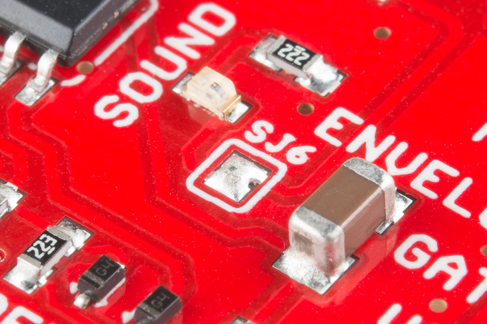
Lights Out
In some applications, the onboard LED may be distracting or undesirable. To disable it, simply use a solder sucker or wick to remove the solder blob from the jumper near the LED.
Physical Considerations
The electret capsule on the Sound Detector is also sensitive to mechanical vibration and wind noise.
The Sound Detector will pick up handling noise. Mounting it with a resilient material can help absorb vibration -- placing it on a piece of open-cell foam helped reject vibration conducted through the testing workbench. Other resilient mounting strategies would include suspending it using rubber bands, or building shock absorbers using #4 machine screws and heat-shrink tubing.
Wind noise is caused when blasts of air enter the capsule. Examples would be a windy day, or the sharp exhalation that often accompanies syllables such "p," "b" and "t." The capsule come with a thin fabric covering, but it may not be enough to prevent stronger blasts. You can craft a more robust windscreen with open-cell foam or synthetic fur (like the covering that sneaks into the frame when a boom mic accidentally enters a film scene).
Software Example
Now that we understand how to configure the board, let's hook it to an Arduino and see what it can do.
Materials
In addition to the Sound Detector, you'll need the following parts.
Connections
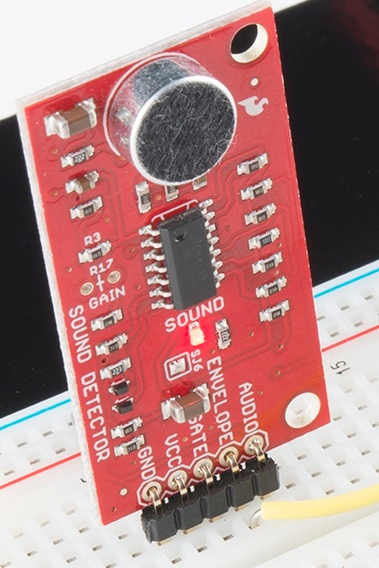
We snapped a 5-pin section off the header, and soldered it to the Sound Detector. Then we took the jumper wires and made the following connections.
(Sound Detector → Arduino )
- GND → Supply Ground
- VCC → Power supply voltage between 3.5 and 5.5 Volts
- Gate → Pin 2
- Envelope → A0
Additionally, as described on the calibration page, a 33K Ohm resistor was soldered into position R17. R3 was left in place, so the gain was lowered from 40 dB to about 28 dB.
language:c
/******************************************************************************
 * sound_detector_demo.ino
 * Sound detector sample sketch
 * Byron Jacquot @ SparkFun Electronics
 * February 19, 2014
 * https://github.com/sparkfun/Sound_Detector
 *
 * This sketch demonstrates the use of the Sparkfun Sound Detector board.
 *
 * The Sound Detector is a small board that combines a microphone and some
 * processing circuitry.  It provides not only an audio output, but also a
 * binary indication of the presence of sound and an analog representation
 * of it's amplitude.
 *
 * This sketch demonstrates two different modes of usage for the Sound
 * Detector.  The gate output (a binary indication that is high when sound
 * is present, and low when conditions are quiet) is used to fire a pin-change
 * ISR, which lights an LED when the sound is present.  The envelope output
 * (an analog voltage to rises to indicate the amplitude of the sound) is
 * sampled in the loop(), and it prints an indication of the level to the
 * serial terminal.
 *
 * For more details about the Sound Detector, please check the hookup guide.
 *
 * Connections:
 * The Sound Detector is connected to the Adrduino as follows:
 * (Sound Detector -> Arduino pin)
 * GND → GND
 * VCC → 5V
 * Gate → Pin 2
 * Envelope → A0
 *
 * Resources:
 * Additional library requirements: none
 *
 * Development environment specifics:
 * Using Arduino IDe 1.0.5
 * Tested on Redboard, 3.3v/8MHz and 5v/16MHz ProMini hardware.
 *
 * This code is beerware; if you see me (or any other SparkFun employee) at the
 * local, and you've found our code helpful, please buy us a round!
 *
 * Distributed as-is; no warranty is given.
 ******************************************************************************/

 // Define hardware connections
#define PIN_GATE_IN 2
#define IRQ_GATE_IN  0
#define PIN_LED_OUT 13
#define PIN_ANALOG_IN A0

// soundISR()
// This function is installed as an interrupt service routine for the pin
// change interrupt.  When digital input 2 changes state, this routine
// is called.
// It queries the state of that pin, and sets the onboard LED to reflect that
// pin's state.
void soundISR()
{
  int pin_val;

  pin_val = digitalRead(PIN_GATE_IN);
  digitalWrite(PIN_LED_OUT, pin_val);
}

void setup()
{
  Serial.begin(9600);

  //  Configure LED pin as output
  pinMode(PIN_LED_OUT, OUTPUT);

  // configure input to interrupt
  pinMode(PIN_GATE_IN, INPUT);
  attachInterrupt(IRQ_GATE_IN, soundISR, CHANGE);

  // Display status
  Serial.println("Initialized");
}

void loop()
{
  int value;

  // Check the envelope input
  value = analogRead(PIN_ANALOG_IN);

  // Convert envelope value into a message
  Serial.print("Status: ");
  if(value <= 10)
  {
    Serial.println("Quiet.");
  }
  else if( (value > 10) && ( value <= 30) )
  {
    Serial.println("Moderate.");
  }
  else if(value > 30)
  {
    Serial.println("Loud.");
  }

  // pause for 1 second
  delay(1000);
}
This code simultaneously demonstrates two different operating modes of the Sound Detector.
- First, using the external interrupt facility, the Arduino observes the gate output, and sets the onboard (pin 13) LED to follow the gate status.
- Second, in the loop() routine, it uses an analog input to periodically sample the envelope signal. That value is interpreted into a message indicating the current loudness via a series of thresholds.
Analog Example
As a purely analog circuit, the Sound Detector isn't limited to strictly being a peripheral for a microcontroller. To illustrate an alternate application, we've wired up a completely analog example. We've tied the envelope output to an LM3916 VU bar-graph LED driver, to make a visual sound level meter. For this application, the Sound Detector is configured with no resistor for R17, and the default 100K in position R3.
Materials
Again, we start with the Sound Detector, then add the following parts.
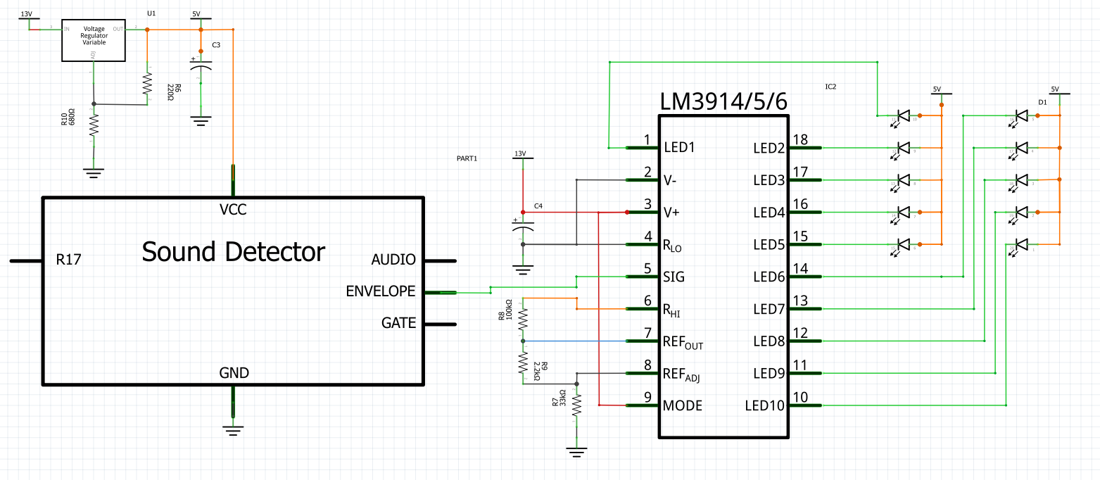
Schematic
We connect those parts as follows.
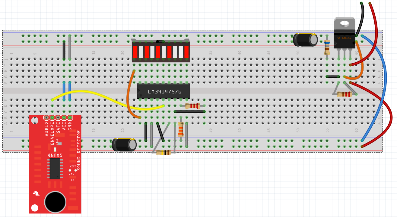
Which translates thusly onto a solderless breadboard.
The assembled, operational version looks like this.
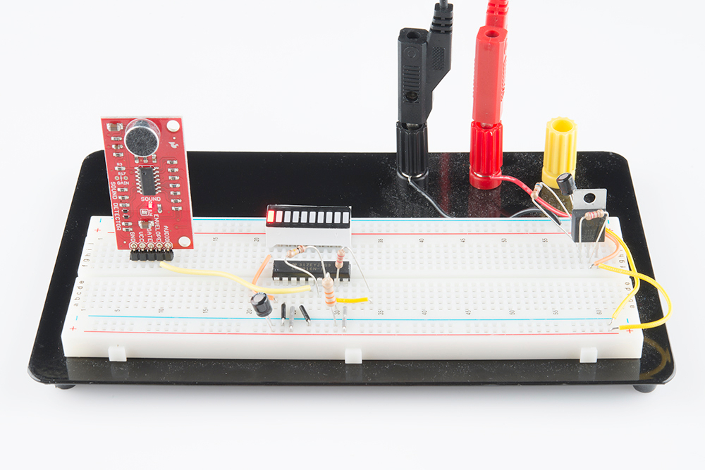
Sound picked up by the microphone is now translated onto the bar graph. The louder the sound is, the more LEDs light up!
A few of notes about the circuit.
- It uses two power supply rails. An external supply was used as a source of 13 VDC. The 13V is further regulated down to 5V using an LM317 adjustable regulator. This provides the recommended minimum of 12V for the bar-graph driver, and a stable source of 5V for the Sound Detector.
- The 5V is connected to the + rail at the top of the breadboard. It is used to power the Sound Detector, and as the anode supply for the LEDs.
- The 13V is on the lower + rail, and is the power supply for the LM3916.
- The 100K Ohm resistor between pins 6 and 7 of the LM3916 sets the reference for the scaling of the bar graph. If the meter seems to be too sensitive, it can be reduced to 10K or lower.
- Pin 6 of the LED bar graph is at one of the covered-over positions on the power rail. The leg was folded over to make contact with pin 5.
- Pin 9 of the LM3916 sets the chip for dot or bar modes. As shown above, tied to the 13V rail, the chip is in bar mode. If pin 9 is left unconnected, the chip will be in dot mode.
Resources and Going Further
A few parting thoughts.
Troubleshooting:
If the Sound Detector is misbehaving, try the following steps.
- Double check that the power supply is clean, preferably with an oscilloscope. Irregularities on the supply will likely be present on the output.
- The gain configuration is easier to tame with the higher headroom offered by higher supply voltages. Providing the Sound Detector with a stable 5V supply, and translating output down to 3.3V will yield better results than powering the detector directly from 3.3V.
- Finally, listen to the audio output. AC-couple the audio output using a 10 uF electrolytic capacitor, with its + leg to the sound detector, and connect a small speaker or headphone. Simply listening to the output often yields clues as to what's wrong.
- You'll be able to hear whether unexpected noises, such as wind and vibration, are being picked up.
- If the audio output is distorted, the gain may need to be reduced.
- If the audio output is really quiet, the gain may need to be increased.
- If there is a constant tone on the audio output, double-check that the power supply is suitably stable. Switch-mode power supplies often introduce oscillations on the power rails.
Documentation
Design files for the Sound Detector are in the corresponding GitHub repository. This includes the Eagle files, and the Arduino example and Fritzing example we explored above.
Additionally, there are SPICE simulations of the circuit for LT Spice. One of those simulations, sound_detector-wav.asc actually analyzes the contents of a wav file (which was used to generate the diagram on page 2 of this tutorial), though you'll have to modify the file path to analyze a wav file if your own.
Finally, the Sound Detector has been added to the sensors category in the Sparkfun Fritzing Library.
See Also
- The Wikipedia page for electret microphones
- LM3914/5/6 Dot/Bar Display Driver Hookup Guide